Week 8 - Challenge 2 - Switch Bezel Design
SWITCH BEZEL
AIM:
To Create the Switch Bezel Plastic component through the given Class-A surface. The tooling axis for the given Class-A Surface should be created meeting the requirements of the draft angle and also Create the Class B Surface & Class C Surface. At the end perform to give thickness of the model.
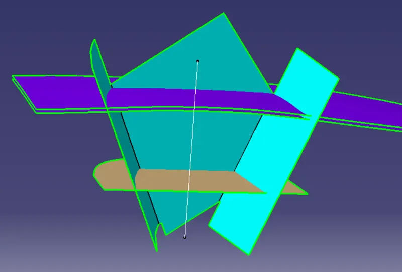
- Create bisecting line for the extended line along the center point on both the line and name it as Tooling Axis.
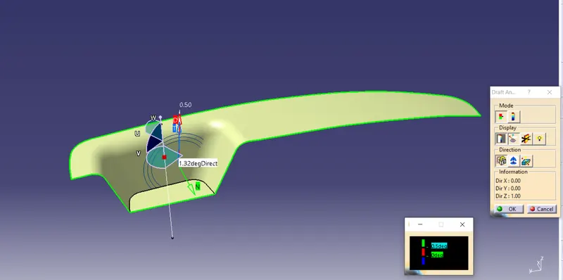
- Extract the 3 wall surfaces from switch bezel
- To be followed by below figure.
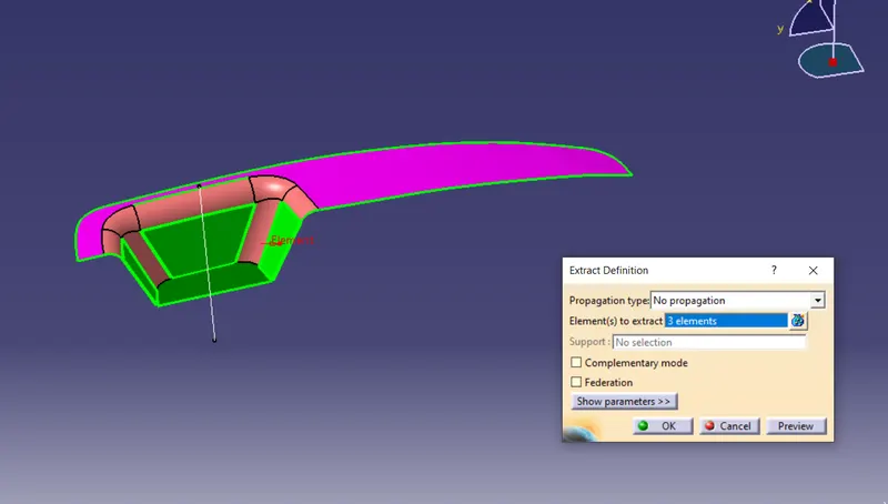
- Extract 3 surfaces from the class a surface to create walls with the help of unitrim.
- Performing the untrim operation and extrapolating in order to increase the length
Then offset the surface in order to get the required thickness.
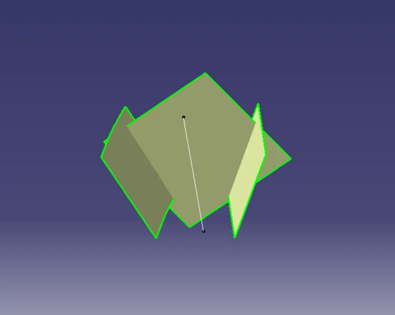
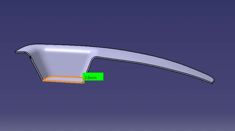
- offset the base surface into 2.5mm.
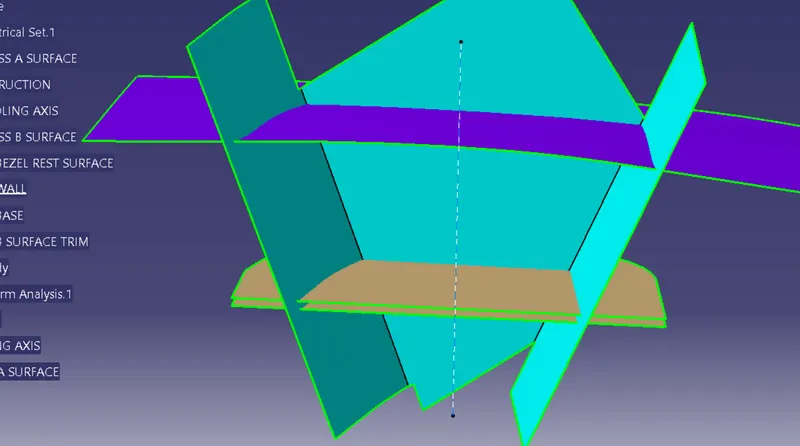
- Create the base of bezel surface.
CLASS B SURFACE:
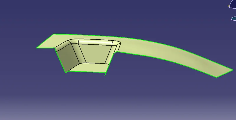
- To the value of the thickness of the component to get B Surface. It is a surface it gives thickness from Class A Surface, all the engineering features like screw bar,ribs and other supporting features could be form on the B Surface. In other tream Class B Surface know as Engineering Surface.
- Below figure is know as Class B surface.
- TRIM SURFACE B AND CLASS A SURFACE.
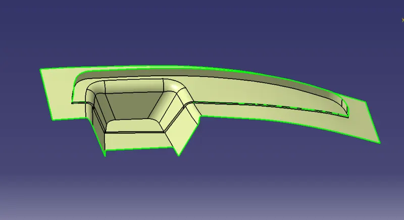
- The below figure is know as Class C surface.
CLOSED SURFACE:
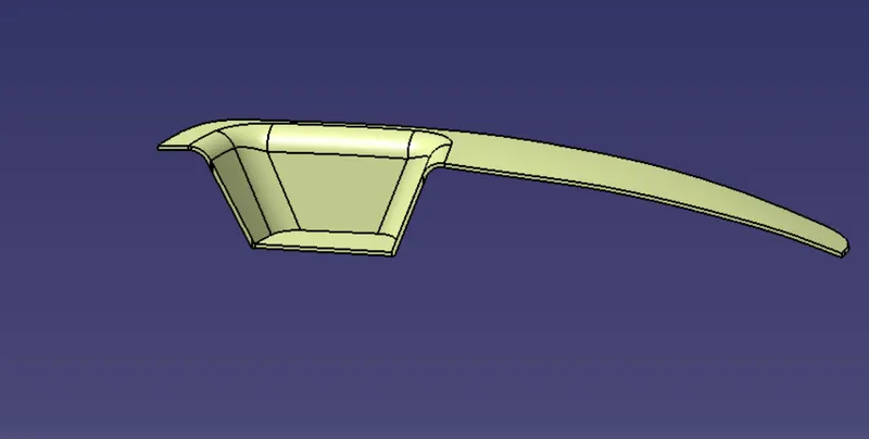
- Close surface is alos known as thickness of the model.
- Go to part modeling & click the close surface option it create complete model of surface.
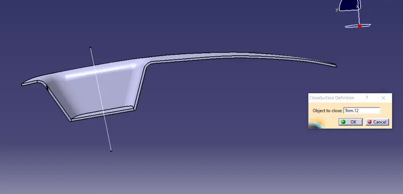
- Give the thickness of switch bezel is 2.5mm .
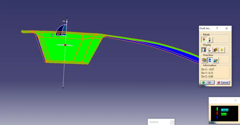
- Below figure is know as draft analysis of the switch bezel.
- Click on the part make sure that the colour code becomes green
- Draft analysis of the thicken switch bezel model.
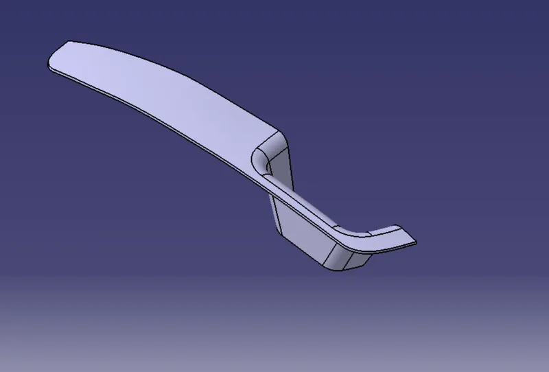
VIEWS:
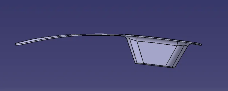
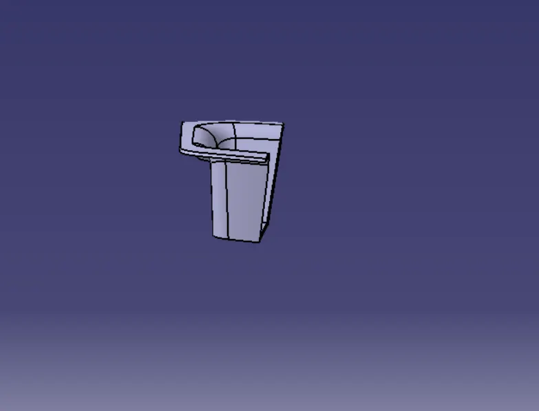
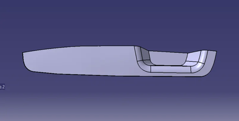
CONCLUSION:
- At the end of this model, we can get the complete profile of base bracket, also the thickness of the component.