Week 8 - Challenge 6 - Core & Cavity Design
CORE AND CAVITY FOR SWITCH BEZEL
Core & Cavity Separation workbench: Import of the Molded Part (Skrinkage operation during the Import operation) Direction management (Add Main Pulling direction, Add Slider direction, Add Axis system) Mold area management (Move faces from a Mold area to an other, Split faces, Add Faces in a Mold area) Extract Parting.
CLASS A SURFACE:
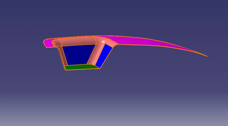
Use Boundary Operation to extract the boundary of the Class A Surface
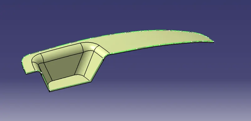
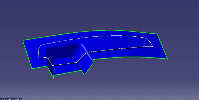
CORE BLOCK
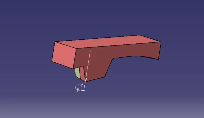
- Extraxct the outer top boundary of the Core Block and Fill the top to create a closed Surface.
- Join the Fill surface and the Extrude of Core
- Trim it with the Parting Surface to obtain the Core Block eclosed Surface
INTERSECTION VIEW:
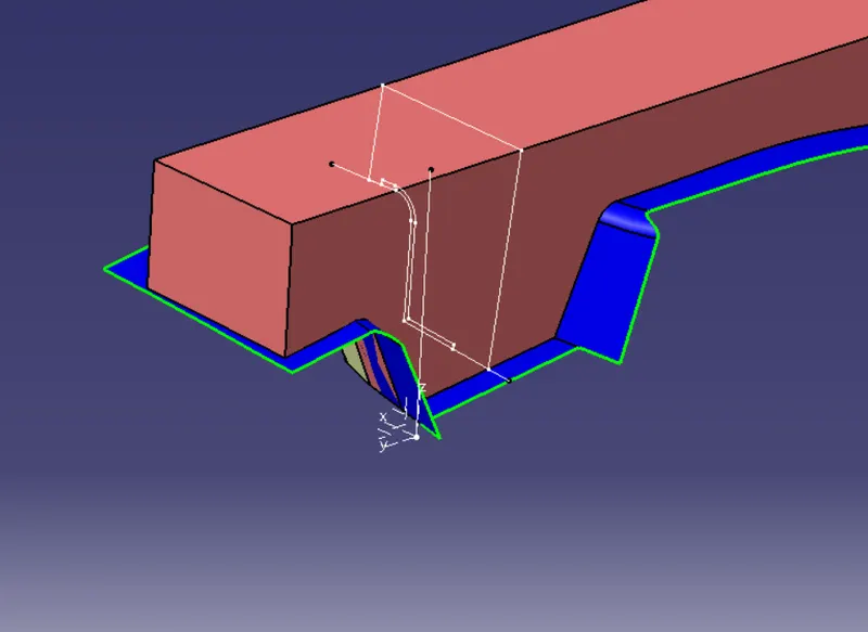
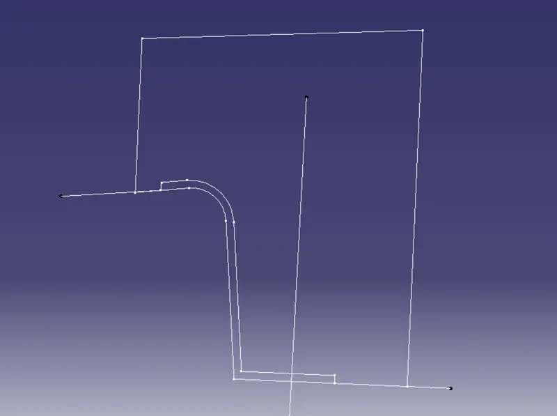
TO CREATE CAVITY WITH THE HELP OF EXTRUDE THE INTERSECTION SURFACE
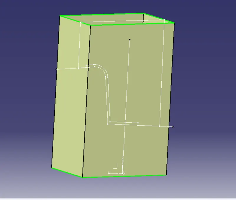
TRIM ALONG WITHE THE B SURFACE:
- Create a rectangular sketch on the Plane - Normal to the Parting Surface aand Extrude the Sketch to create the Core surface
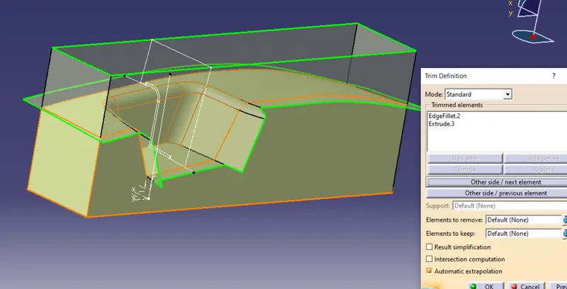
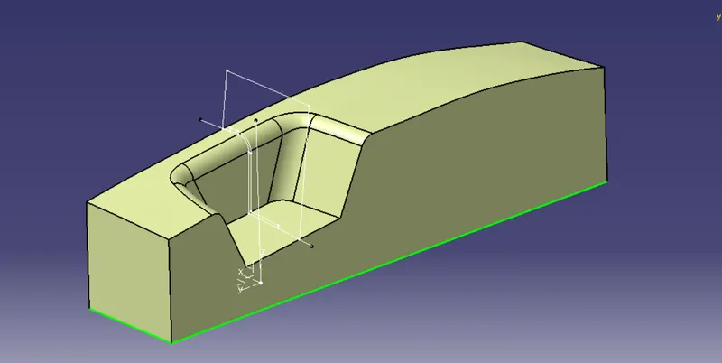
FILL THE BOTTOM SURFACE AND FILL IT TOGETHER
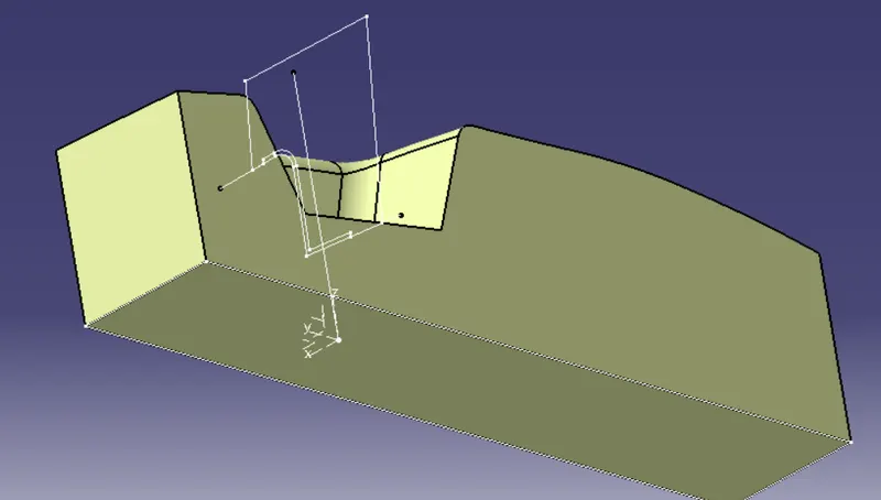
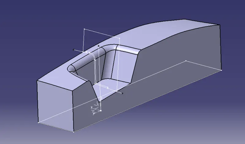
CORE AND CAVITY
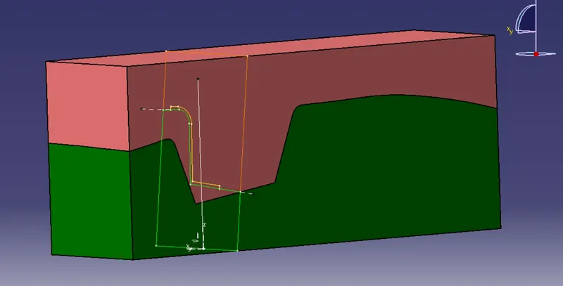
PARTING SURFACE AND COMPONENT
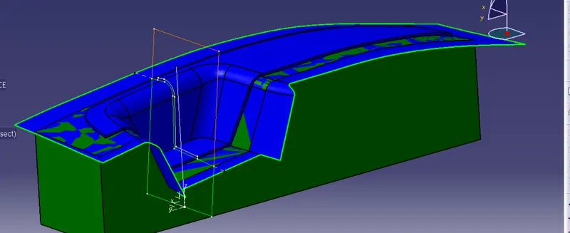
SPLIT AND INTERSECT WITH B SURFACE:
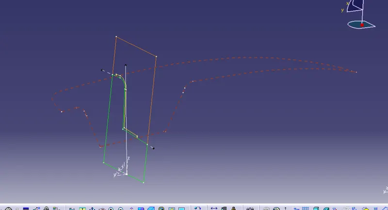
ACTUAL PARTING SURFACE:
Use The Intersection of Final Trim and the Parting Surface for Creation of Parting.
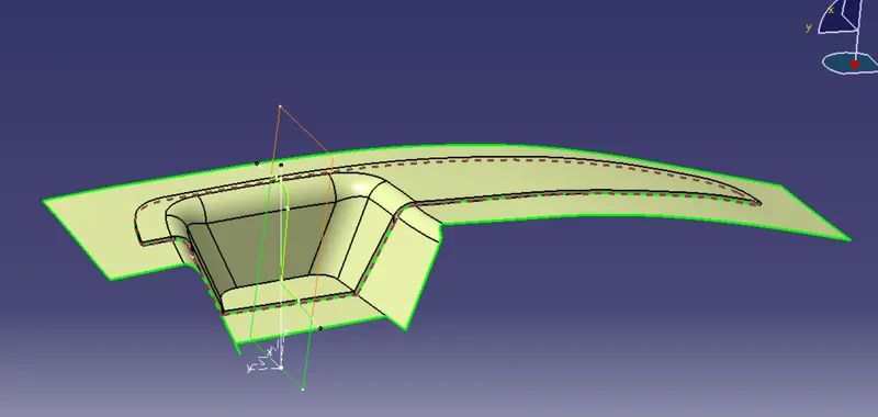
FINAL OVER VIEW
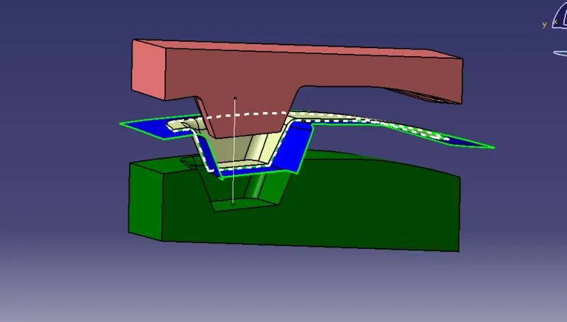
Conclusion:
The Design of Core and Cavity for the Mold of Automotive Plastic Component – Door Switch Bezel is completed using concepts of Parting Surface, Parting Line, Draft angle, Draft Analysis for Class A and Final enclosed surface, Tooling Axis creation and implementation, Class B and Class C creation and conversion to a solid part maintaining the part thickness at 2.5mm.