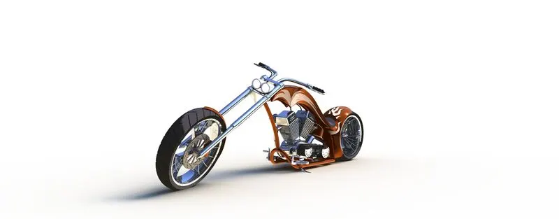
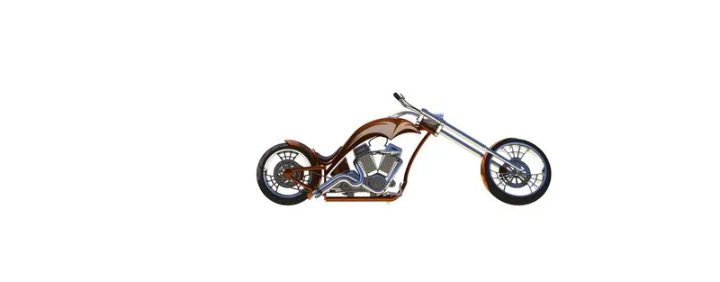
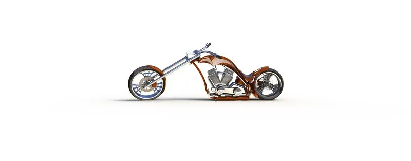
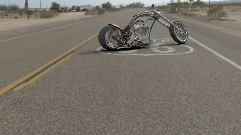
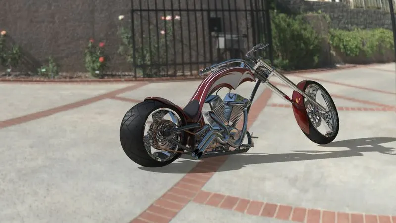
Photo Realistic Rendering
Design the American chopper
Objective
- The objective of this project is to design the bike(American chopper) on the Solidworks to learn the Solidworks and its feature
introduction
- In this project we design the bike in Solidworks by using a blueprint sketch of the chopper, that was required to design, In this project I learned a lot of features that Solidworks had to simplify the process, In this project, we design the chopper as multiple 3D parts and finally assembled it and process the render to like the model as a more realistic view on the rendered image
Design methodology
Part
- sketch the dimension in 2D with respect to the blueprint
- Feature tools to create solid or surface parts and features like fillet,champer, etc ...
- curve options are used to project curves in 3d
Assembly
- Insert and constrain the parts with respective planes or components (chassis)
- Make miss-alignment parts with their alignment and not collied with other components(check the parts are well designed
Render
- Create a camera and adjust the feature like perspective and view to look realistic
- Edit the effects like lights, view, rendering properties, environment, scene to create the model look more realistic
Description
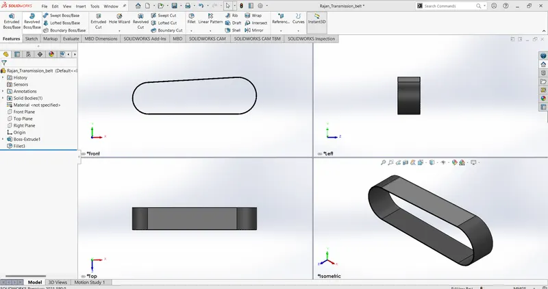
- Lines
used to create a line
- Arc
used to create an arc
- offset
used to create offset (to avoid sketching similar sketch)
- extrude
used to create a 3D parts from 2D sketch
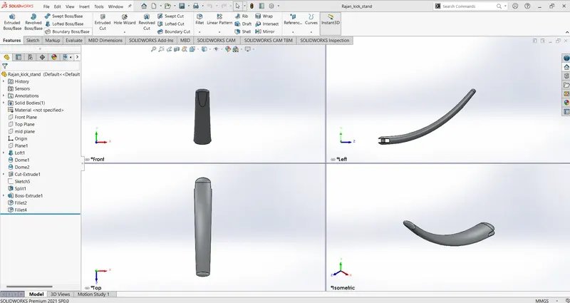
- extrude
used to create a 3D parts from 2D sketch
- eclipse
used to draw eclipse on both ends
- spline
used to create a spline to connect both eclipses
- loft
used to create a curvature surface between eclipse
- dome
used to create dome at eclipse face
- cut extrude
used to cut unnecessary area
- fillet
used to create rounded corners
- split
used to cut or split the part into two or more bodies by used sketch or intersecting areas
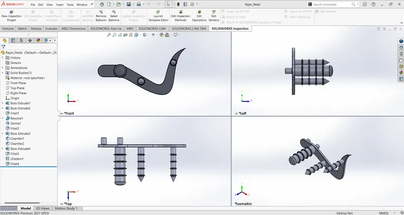
similar tools are used in this also:
- line,fillet,extrude,dome
- revolve
used to create a cylindrical part by sketching a sectional 2D view and revolving it with the respective axis
- champer
used to create champer on the edges
- liner patten
linearly copy the features and pattern it as per the requirement
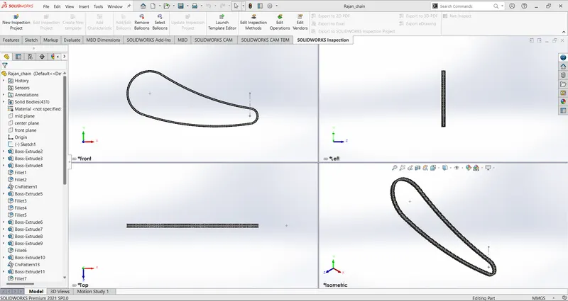
similar tools and features used
- arc,extrude,fillet
- curve driven
used to create a pattern on cure
- slot
used to sketch a slot on the 2D sketch
- mirror
used to mirror the required part with the respective plane
- block
used to save a 2d sketch and used it for multiple times
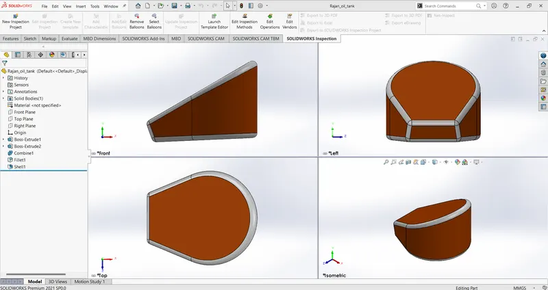
this part also used similar tools and features
newly used features
- shell
used to create a hollow part
- combine
used to combine two or more bodies (add, cut, intersect)
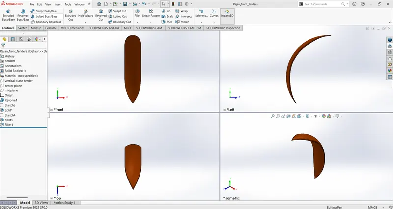
in this part also above mentioned tools and features are used -revolve and split
- trim(extend entities)
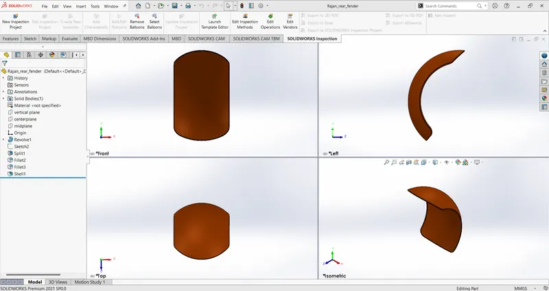
in this part no new tools and features are used -revolve and shell
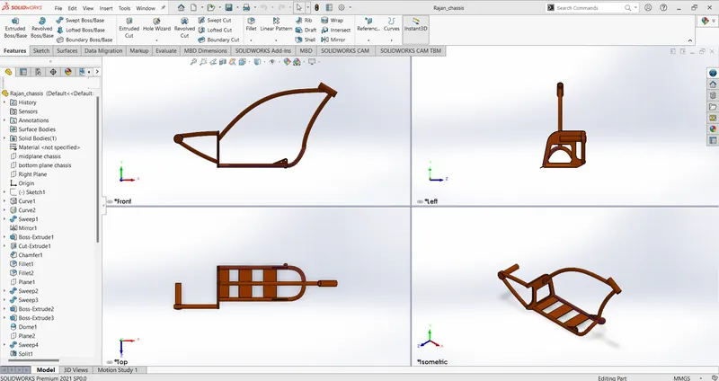
in this part also I applied the tool and features used before
newly used feature
- sweep
used to create a 3D model along with the selected path
- curves(projected)
used to create the 3D curve(intersection of 2 curves) by combining 2 curves on a different plane
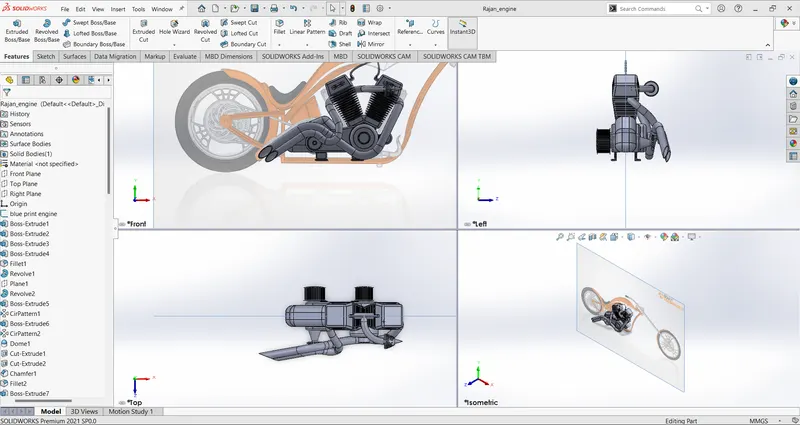
In this part, I used all the features and tools used above to create this part
newly used feature
- composite curve
used to join the two projected curves
- circular pattern
used to pattern a feature in a circular path
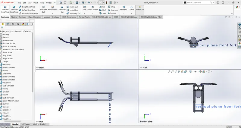
In this part, I used all the features and tools used above to create this part
newly used feature
- cut revolve
similar to revolve but it removes the matirials
- move/copy
used to more or copy and paste the part with given alignment
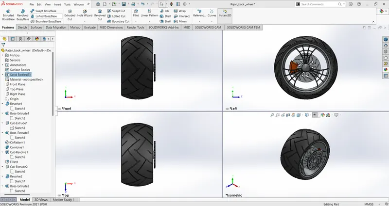
In this part, I used the features and tools used above to create this part
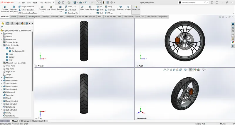
In this part, I used the features and tools used above to create this part
The relation also used to determine the position and relation of the sketch and part to fix it in the required position
- horizontal
- vertical
- parallel
- concentric
- coincide
- colinear etc...
Assembly
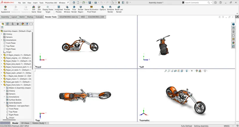
mates are used to fixing the parts at their respective positions
mates are relation on the assembly
Renders
Renders are used to present the designed models into photo-realistic view