Photo Realistic Rendering
PHOTO REALISTIC RENDERING OF AMERICAN CHOPPER
Objective:-To explain the features & Techniques used in creating each & every individual part, assembling them & how to generate photo realistic rendered image of American chopper.
Introduction:- American chopper is basically theme bike made by orange county choppers(OCC),which was featured in "American Chopper " television series way back in 2003-04.
Theme bikes are the motorcycles in which theme of motorcycle takes priority over everything else, influencing the frame dimensions, paint scheme & overall feel of the motorcycle. the function of the motorcycle usually takes a backseat to the presentation of the theme, and these motorcycles attract attention solely on the premise of the theme itself.
Design Methodology:-
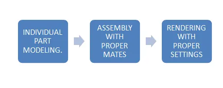
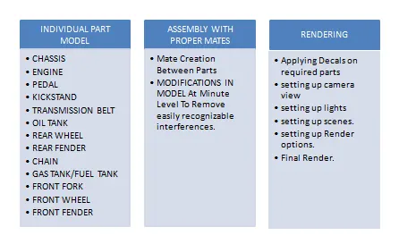
Description:-
Type of tools/features used in creating these models are as follows:-
- Boss-Extrude:-it converts 2D sketch to 3D object with 3rd dimensions as height/thickness in model.
- Revolve:-it converts 2D sketch or section with reference axis to 3D body.
- Cut- Extrude:- Removes portion of material or amount of specified value from solid body.
- Cut-Revolve:- similar to Revolve but it removes material or a circular cut can be created in a body.
- Sweep:- it requires 1 path and 1 profile to create solid body.
- Cut-Sweep:- simular to sweep but it is used to create cut.
- Combine:- this feature combines the two bodies.
- Fillet:- it is used to create rounds at sharp edges with specified radius value.
- Chamfer:- used to blend sharp edges with various options as symmetric or assymetric,distance-distance,distance-angle.
- Dome:- used to create dome shape on flat face with specified value.
- Loft:- needed atleast two sketch and 1 path line to create lofted body useful in case of varying cross sections.
- Split:- as the name suggests it can split bodies with the use of Sketch,planes,surfaces as trim tool.
- Linear pattern:- used to create identical bodies at a specified intervals or you can skip some instances if needed.
- Circular pattern:-used to create identical bodies at an equal circumferential spacing.
- Mirror:- with the help of any reference plane it can mirror the body.
- Projected curve:- most important features in terms of complex 3D modeling which helps to create / generate path line.
- Composite curve:- used to join 2 3D curve,projected curve to as a result act as single entity.
- Sketch blocks:- if a single simple sketch entity is repeatedly required in any model,then creating sketch block of it is the best option & insert it as required.
- Move Body:- with these option body can either be only reorient or reoriented as a copy.
- Surface sweep:- here only surface is created along path with profile.
- Boundary surface:- with this option close Boundary surface are created with profiles and directions.
- Surface extrude:- it can generate surface with just single linear curve but need to specify direction.
- Surface loft:-it needed two curve or lines and 1 direction or path line.
- Surface knit:- knits the selected surface and produces it to be a single surface result it it forms a completely closed surface then possibly it can create solid body out of it.
- SHELL:- with the help of this feature able to create thin sections bodies or thin walled bodies,either closed or open face.
1. CHASSIS:-
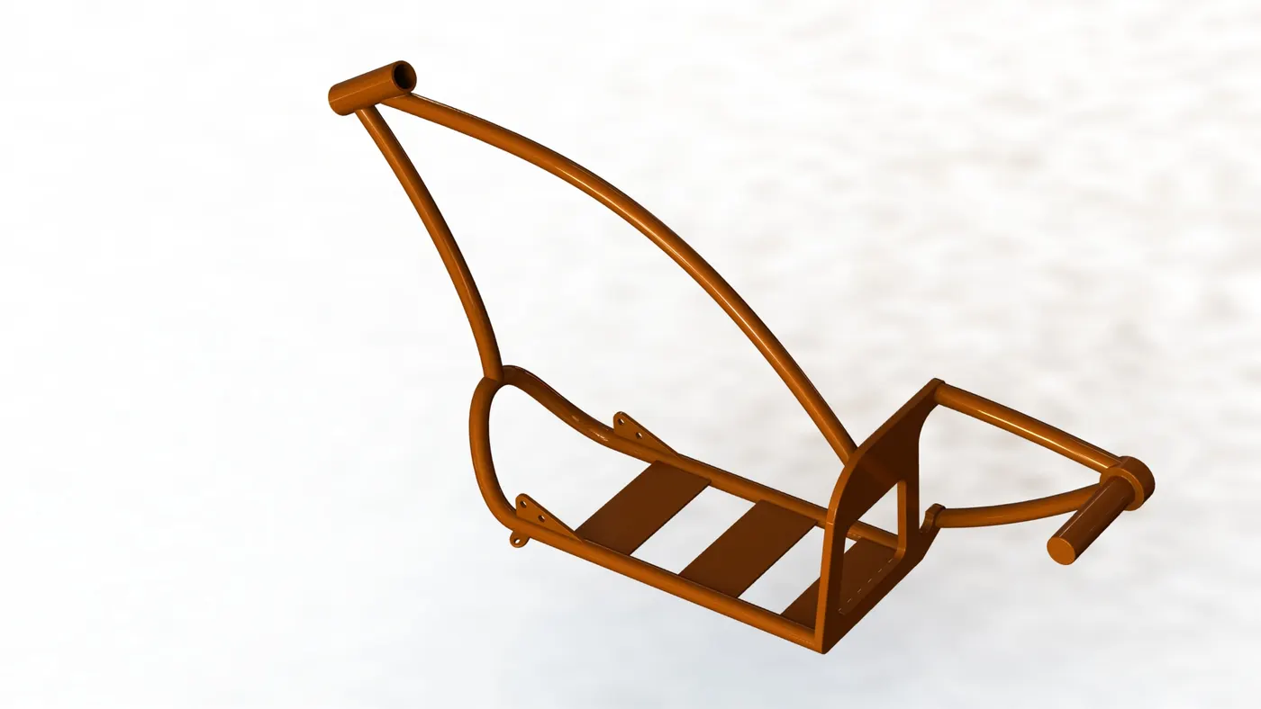
- projected curve.
- Sweep.
- Boss-Extrude.
- Cut-Extrude.
- Mirror.
- fillet.
- chamfer.
- dome.
- split.
- combine.
2. ENGINE:-
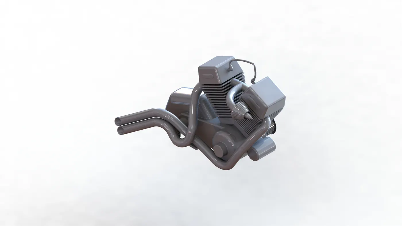
- Boss-Extrude.
- Revolve.
- fillet.
- chamfer.
- dome.
- Cut-Extrude.
- linear pattern.
- Circular pattern.
- Mirror.
- Sweep
- Combine.
- projected Curve.
- composite curve.
- Split.
3.PEDAL:-
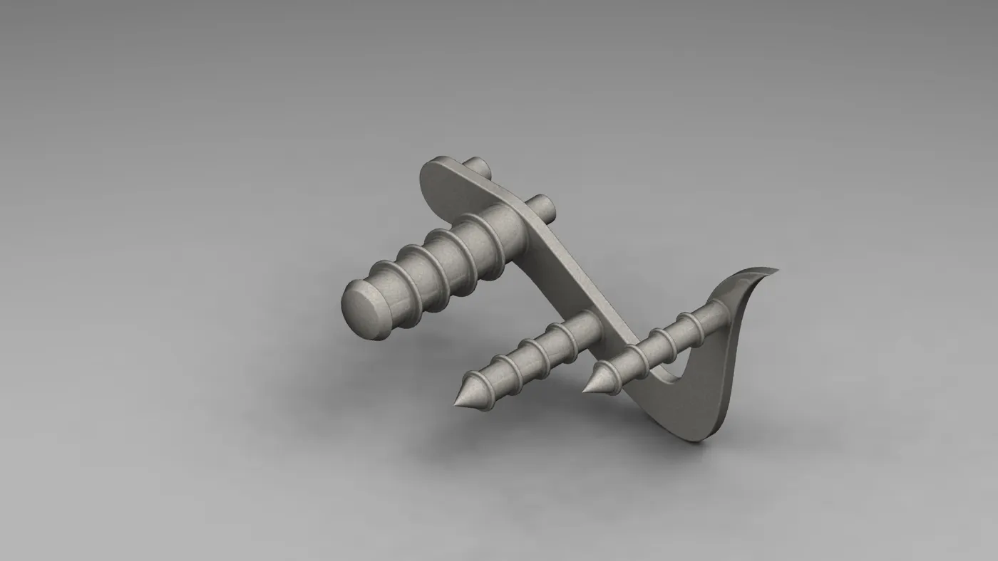
- Boss-Extrude.
- Revolve.
- dome.
- fillet.
- chamfer.
4.KICKSTAND:-
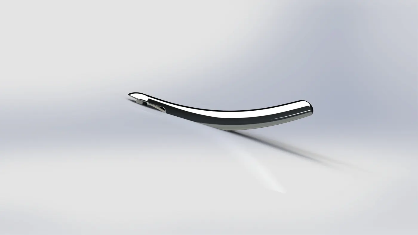
- Boss-Extrude.
- Cut-Extrude.
- loft.
- split.
- Dome.
- Fillet.
5.TRANSMISSION BELT:-
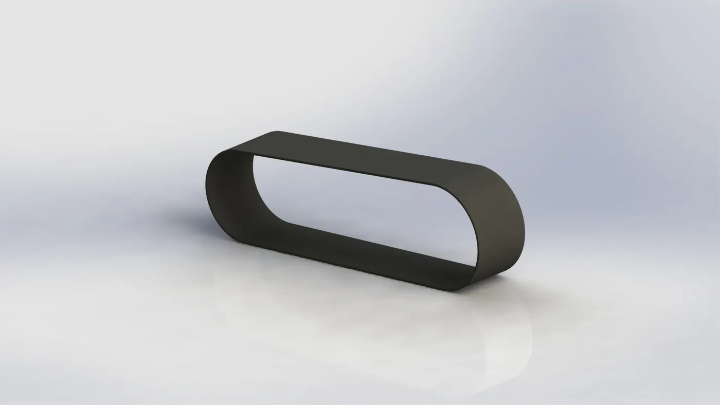
- Boss-Extrude.
- fillet.
6.OIL TANK:-
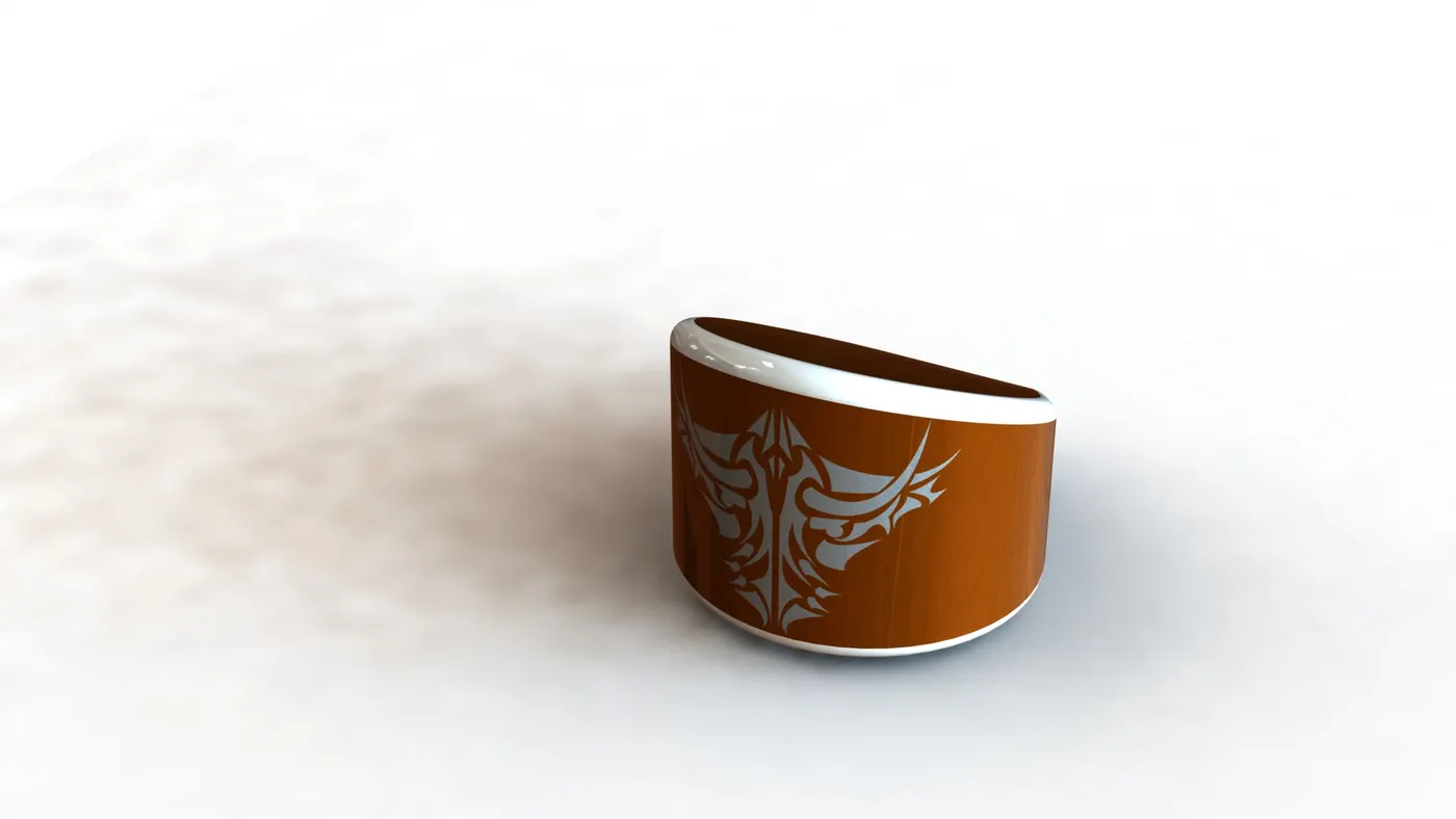
- Boss-Extrude.
- Combine.
- Shell.
- Fillet.
7. REAR WHEEL:-
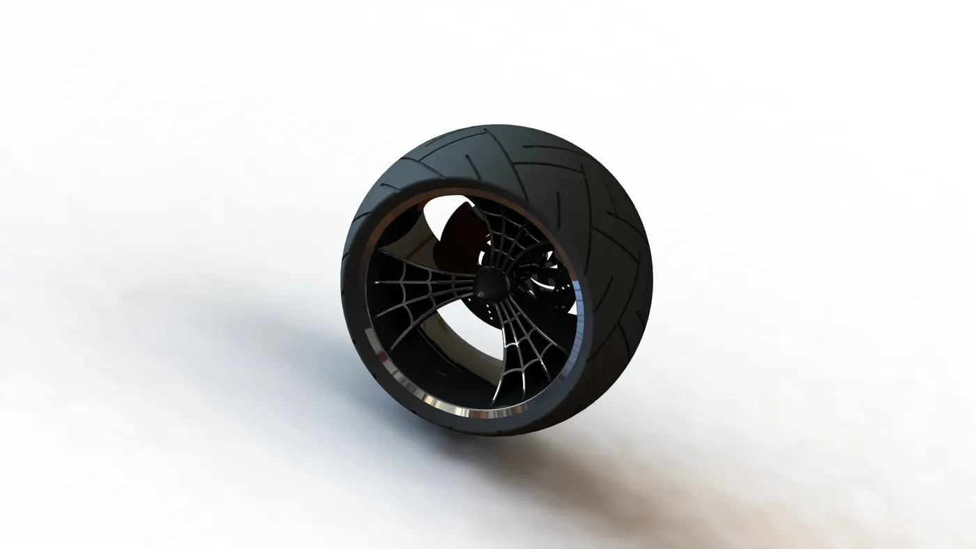
- Boss-Extrude.
- Cut-Extrude.
- Cut-Revolve.
- Revolve.
- combine.
- circular pattern.
- Fillet.
- Chamfer.
8.REAR FENDER:-
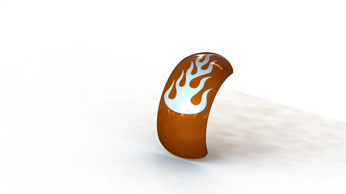
- Revolve
- split
- Fillet.
- Shell.
9.CHAIN:-
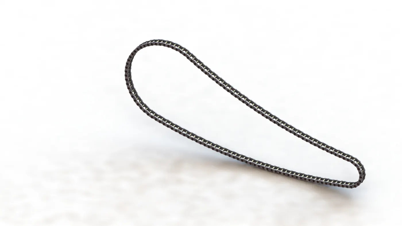
- Sketch Blocks.
- Boss-Extrude.
- Fillet.
- Circular Pattern.
- Mirror.
10.GAS TANK:-
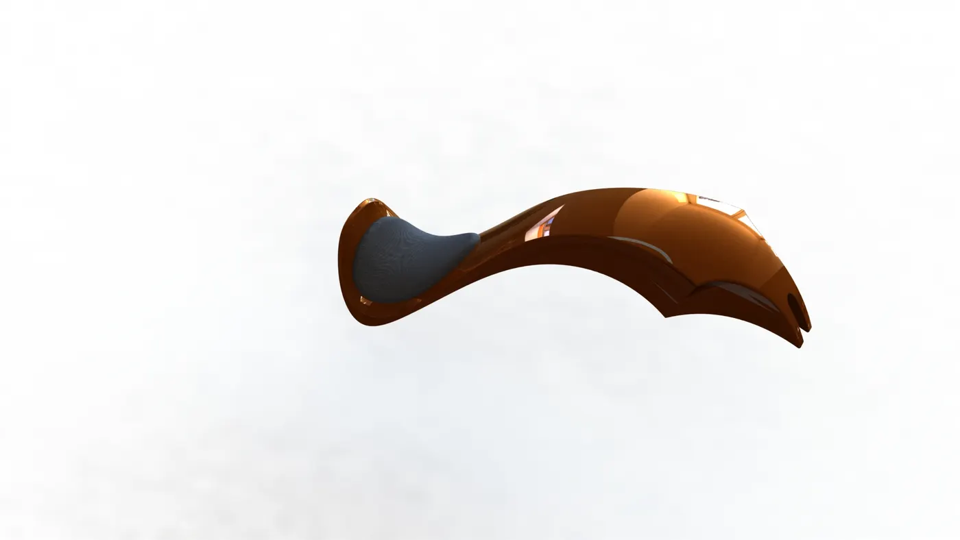
- Surface sweep.
- Split.
- Projected curve.
- Boundary Surface.
- Surface Knit.
- Mirror.
- Surface Loft.
- Surface Extrude.
- Cut-Sweep.
- Shell.
- Fillet.
11.FRONT FORK:-
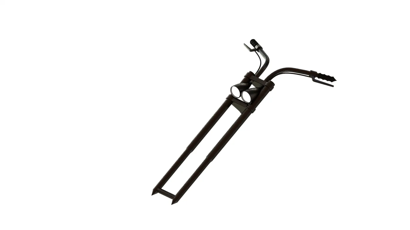
- Boss-Extrude.
- Revolve.
- Cut-Extrude.
- Linear Pattern.
- dome.
- fillet.
- Move Body.
- Sweep.
- Projected Curve.
- Mirror.
- Combine.
12.FRONT WHEEL:-
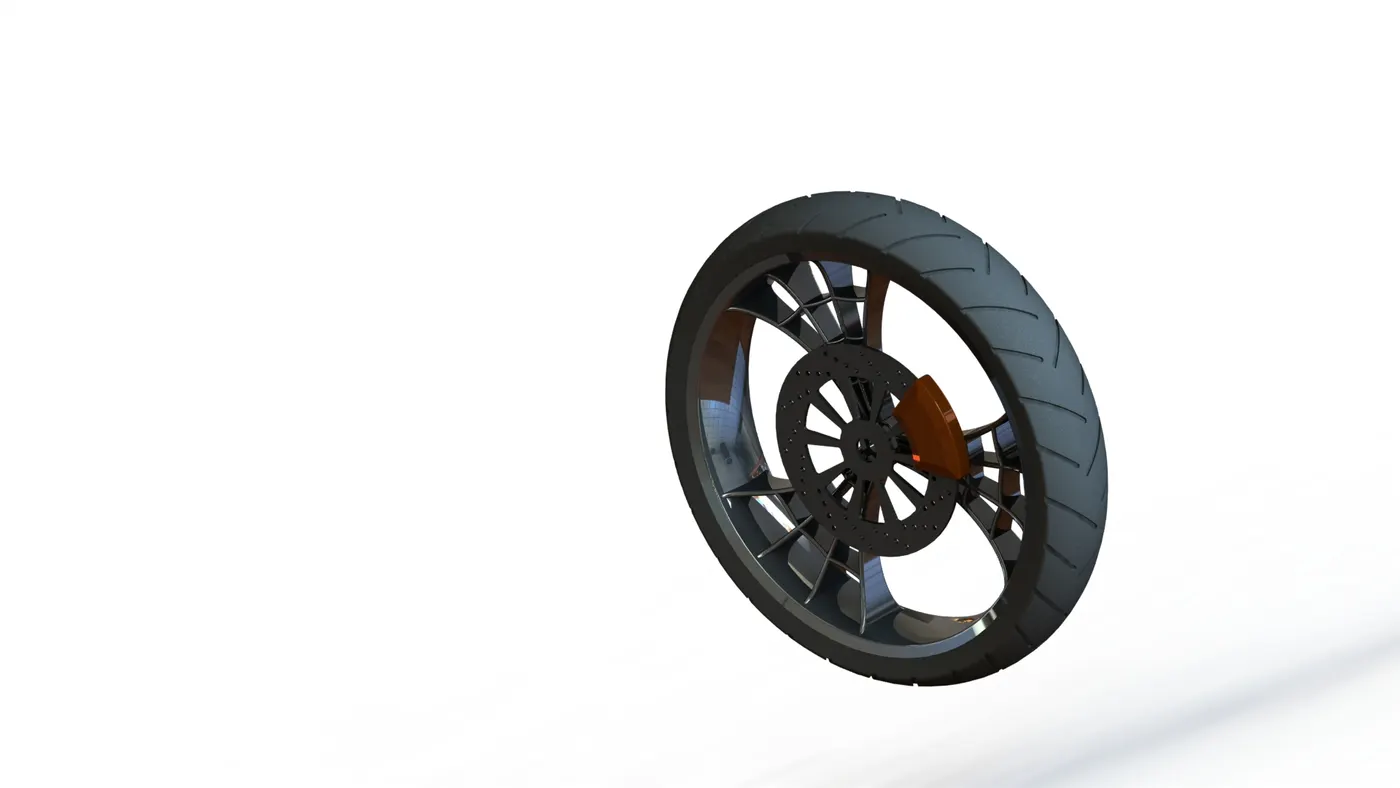
- Boss-Extrude.
- Cut-Extrude.
- Revolve.
- Cut-Revolve.
- Circular pattern.
- Combine.
- Fillet.
- Chamfer.
13 FRONT FENDER:-
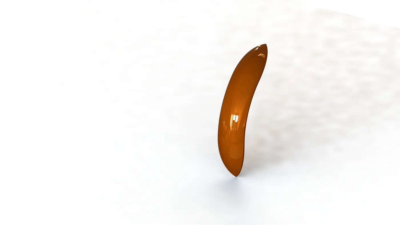
- Revolve.
- Split.
- Shell.
- Fillet.
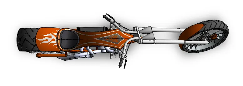
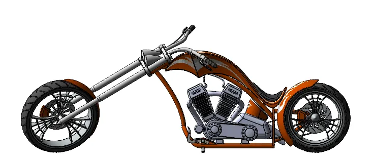
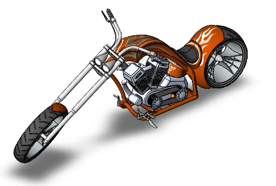
AMERICAN CHOPPER ASSEMBLY MODEL:-
FRONT VIEW:-
TOP VIEW:-
SIDE VIEW:-
ISOMETRIC VIEW:-
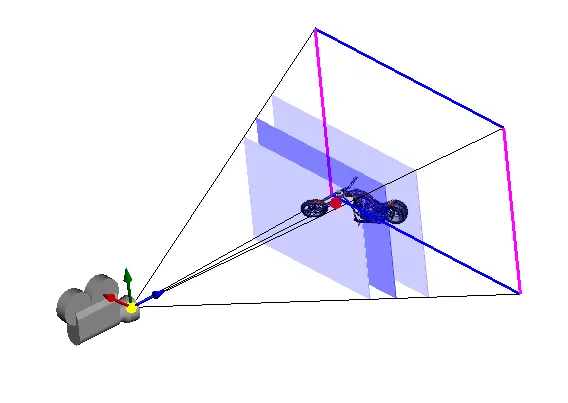
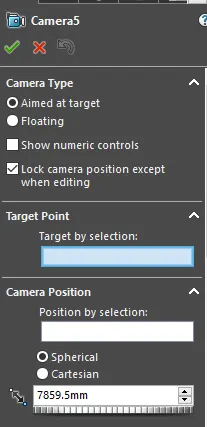
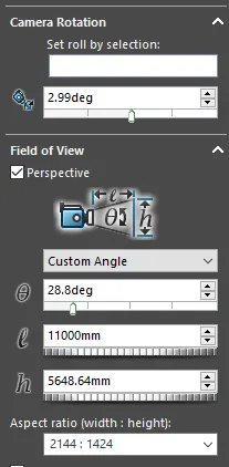
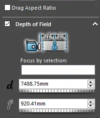
CAMERA SETUP VIEW:-
CAMERA SETUP VIEW SETTINGS:-
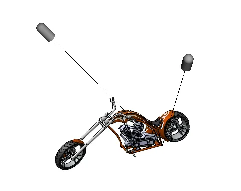
LIGHTS VIEW:-
only 2 directional lights are applied.
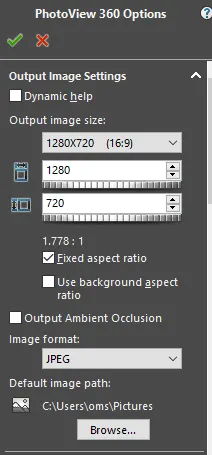
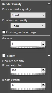
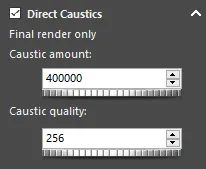
PHOTOVIEW 360 OPTIONS:-
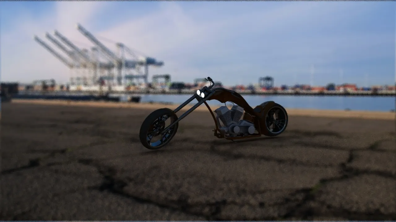
FINAL RENDERED IMAGES:-
First with white background.
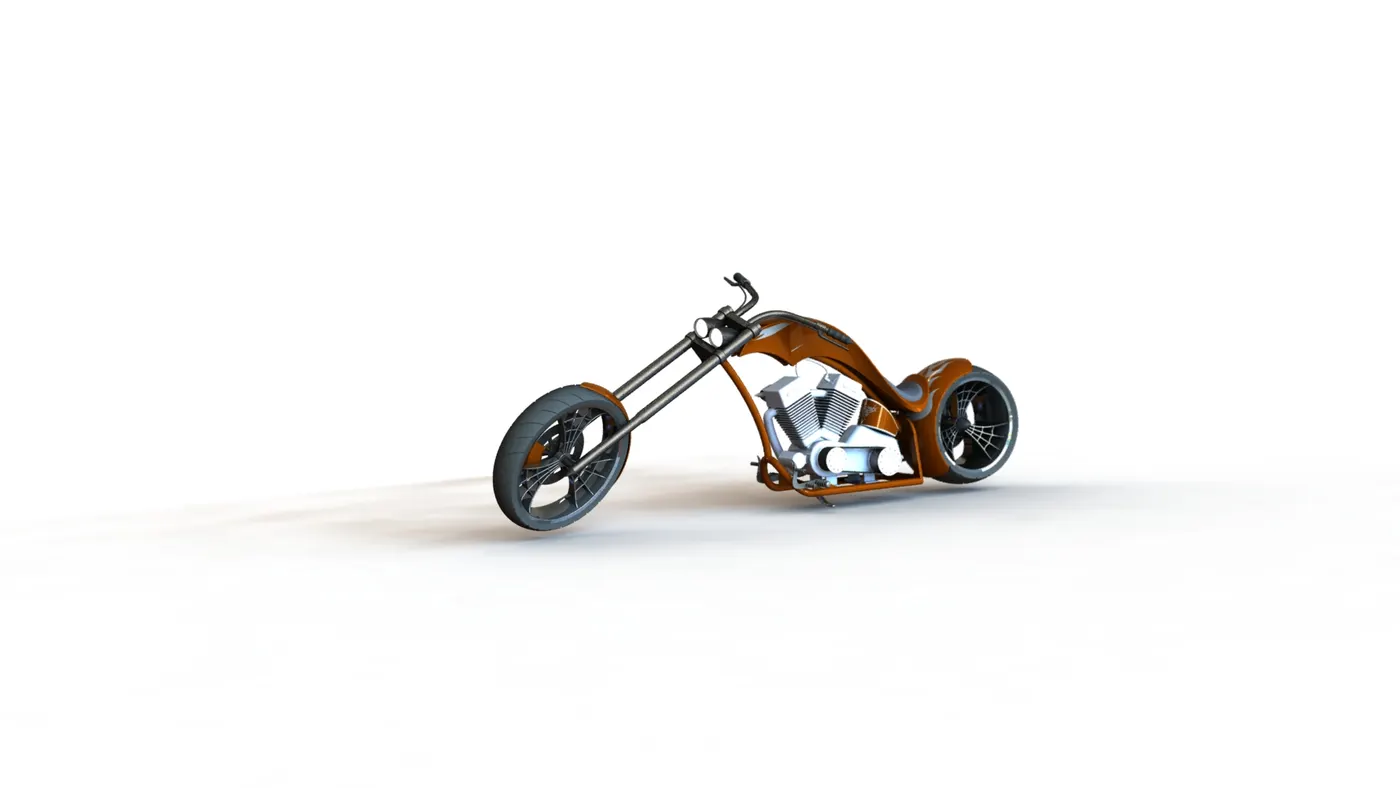
second with urban scene background.
CONCLUSION:-
For generating realistic image from any part model or assembly model, needed to try out multiple camera view then apply lights later on suitable background scene if needed as per requirement, then playing with various variables also keeping in mind operating systems hardware constraint from beginner to expert level & render options.