Photo Realistic Rendering
Title of the Project:-
Designing of an American Chopper and its Components with Photo-Realistic Rendering using SOLIDWORKS
Objective:-
Designing of an American Chopper from scratch to final Rendering of the Model. This Project help to understand the tools in Solidworks by working on a real model.
Introduction:-
Solid Works:-
It is a 3D modeling and simulation based CAD(Computer Aided Design) Software.
Design Methodology:-
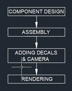
Description:-
Major tools used to complete the American Chopper
1.Creating 2D Sketch:-
A 2D sketch is the base to create the 3D model. It created on x y Axis. It includes Line, Circle, Rectangle, Arc, Spline etc.
2.Geometric Relation:-
It is most Powerful tool in Solidworks. They are used to control the sketch as per the dependency of our requirement.
3.Solid Extrude:-
It extrude a sketch contours in one or two direction to create a solid feature.
4.Extrude Cut:-
This feature helps us to remove the material from a 3D model. It can cut both directions. By this feature we can make holes, slots etc.
5.Revolve Bose:-
By this feature we can create a solid feature of a sketch contours around an axis.
6.Revolve Cut:-
By this feature we can cut a solid model by revolving a solid profile around an axis.
7.Sweep Boss:-
By this feature sweeps a closed profile along with a closed or open path to create a solid feature.
8.Loft:-
By this feature we create a shape by making transition between multiple profiles and guide curves which allow to create complex geometry with a single tool.
9.Dome:-
It is a rounded or elliptical vault forming the outside face of a body structure mainly on a circular base.
10.Curve Driven Pattern:-
By this tool we create a pattern along a planar or 3d curve. We can use any sketch segment that lies along the curve plane.
11.Linear Pattern:-
By this pattern we can create multiple instance of one or more features that we can uniformly along one or two linear paths.
12.Circular Pattern:-
By this pattern we can create multiple instance of one or more features that we can uniformly around an axis.
13.Fillet:-
By this tool we can create a rounded internal or external face of any part.
14.Chamfer:-
By this feature we can connect two adjacent face using an inclined line.
15.Trim:-
By this tool we can remove or erase extra edges of intersecting on a 2D sketch.
16.Offset:-
By specifying distance we can create sketch from a sketch entities.
17.Split:-
By this tool we create multiple parts from an existing parts.
18.Merge/Combine:-
By using this tool we can create a single body from two multiple bodies.
19.Projective Curve:-
By this tool we can create a 3D curve from the intersection of two extruded surfaces generated by creating sketches on two intersecting planes
20.Convert Entities:-
By this tool we can create one or more curves in a sketch by projecting an edge, loop, face, curve, or external sketch contour, set of edges or set of sketch curves onto the sketch plane.
21.Shell:-
By using this tool we can create a hollow on a solid parts
22.Mirror:-
By this we can create a mirror of a sketch along with its face, axis, body or a plane.
23.Surface Knit:-
By this we can combine two or more adjacent, non-intersecting surface together.
Components to be Design:-
- Transmission Belt
- Kick Stand
- Front Fender
- Rear Fender
- Oil Tank
- Pedal
- Chain
- Front Wheel
- Rear Wheel
- Front Fork
- Chassis
- Engine
- Gas Tank
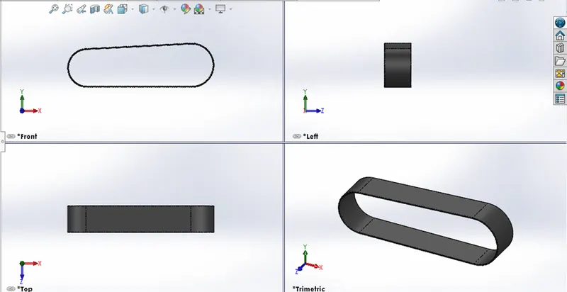
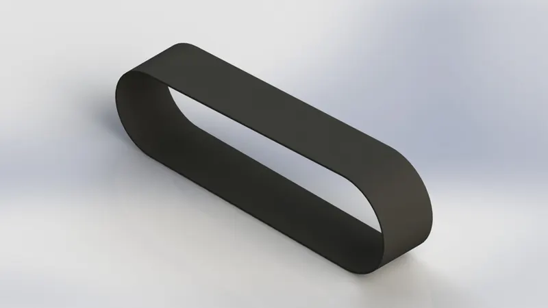
1.Transmission Belt:-
- The Transmission Belt is used to connect the engine pulley with the transmission.
- By using tools like line, curve and extrude bosh base with the needed relations Offset entities, Extrude boss, Fillet and Appearance, etc.
Part Model Image
Render Image
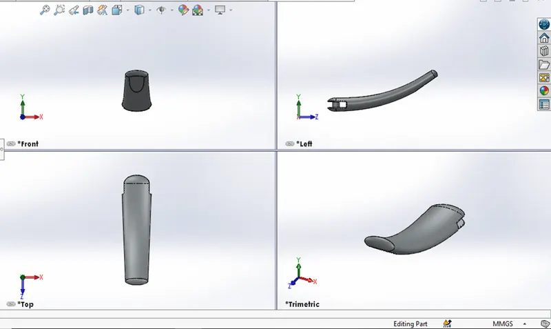
2. Kickstand:-
- Kickstand is used to support the bike to the ground without laying against any other object.
- By using tools like ellipse, Loft boss, Extrude boss, Extrude cut, Dome, Split, Fillets, Appearance, etc.
Part Model Image
Render Image
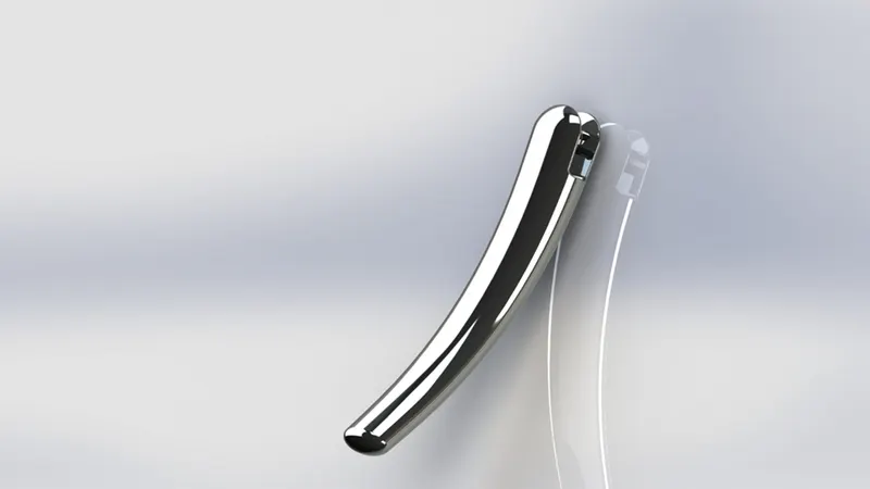
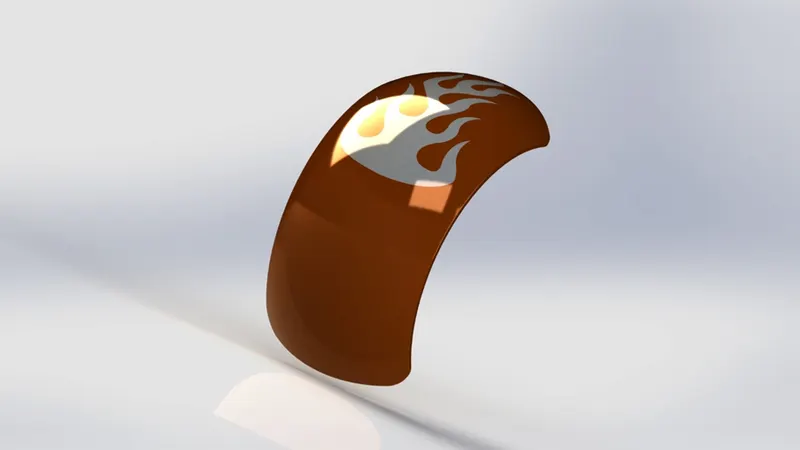
3. Front Fender:-
- Front Fender is used to prevent send, mud etc by rotating the wheel which is placed above the Front Wheel.
- By using tools like 3 point arc, Offset entities, Trim entities, Revolve boss, Dynamic Mirror, Split, Appearance, etc.
Part Model Image
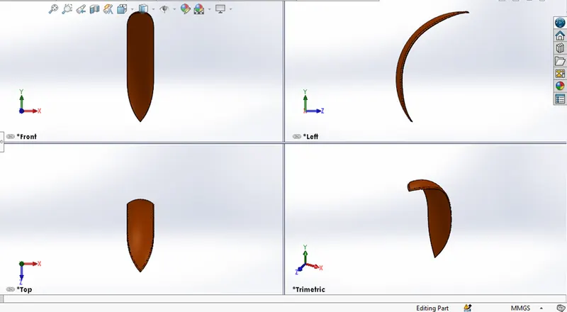
Render Image
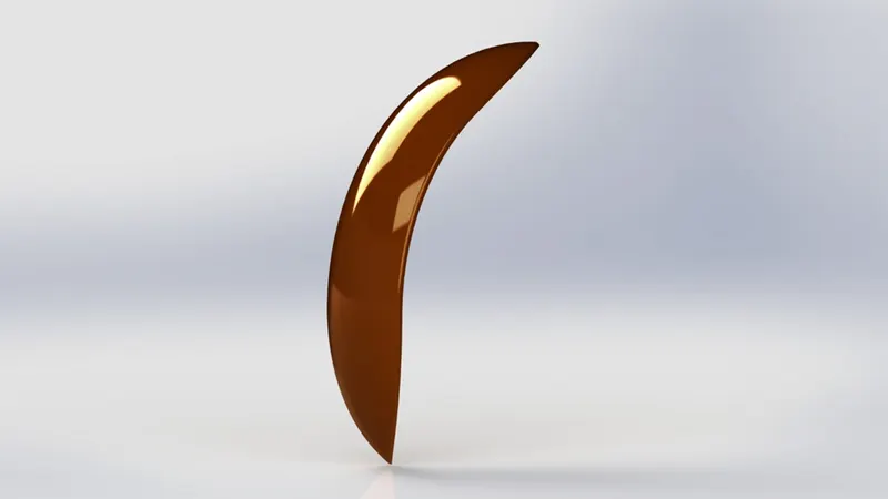
4. Rear Fender:-
- Rear Fender is used to prevent send, mud etc by rotating the wheel which is placed above the Rear Wheel.
- By using tools like 3 point arc, Offset entities, Trim entities, Revolve boss, Appearance, etc.
Part Model Image
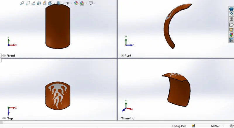
Render Image
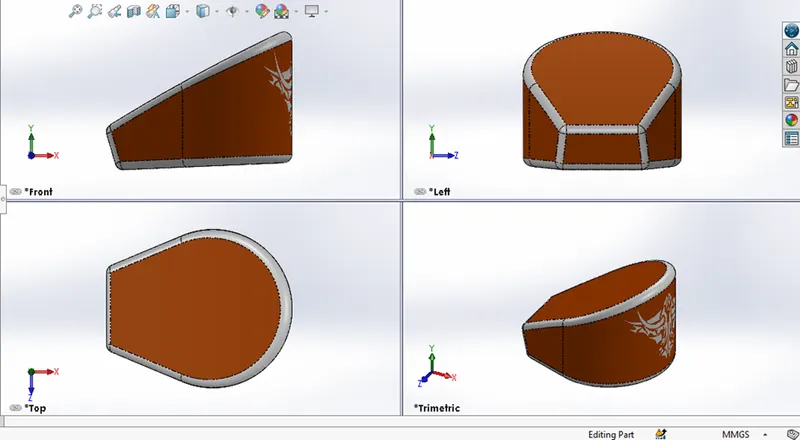
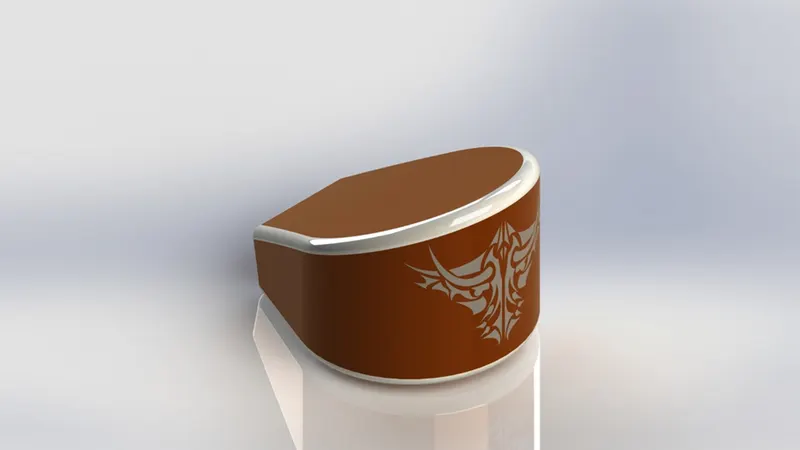
5. Oil Tank:-
- In American Chopper, we have a separate Oil Tank for the engine which is located behind the engine.
- By using tools like Bose extrude, Combine, Fillet, Shell, Appearance, etc and there is a hollow inside the tank.
Part Model Image
Render Image
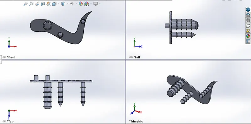
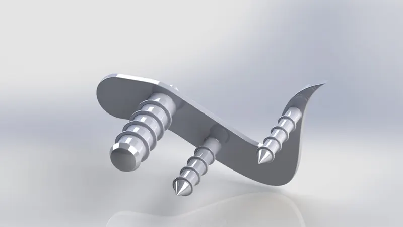
6. Pedal:-
- The Pedal is fixed in the Chassis used for resting the foot.
- By using tools like Extrude boss, Fillet, Linear pattern, Dome, Chamfer, Appearance, etc.
Part Model Image
Render Image
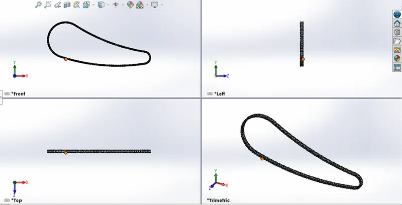
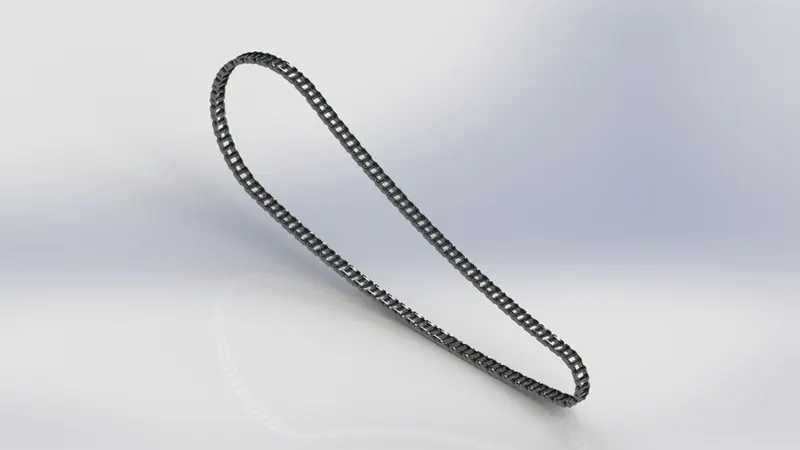
7. Chain:-
- The Chin is used to transfer power from the transmission to the rear wheel.
- By using tools like 3 point arc, Circle, Curve Driven Pattern, Extrude boss, Making blocks, Trim Entities, Fillet, Appearance, etc.
Part Model Image
Render Image
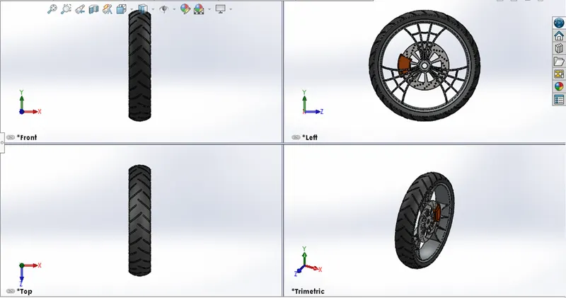
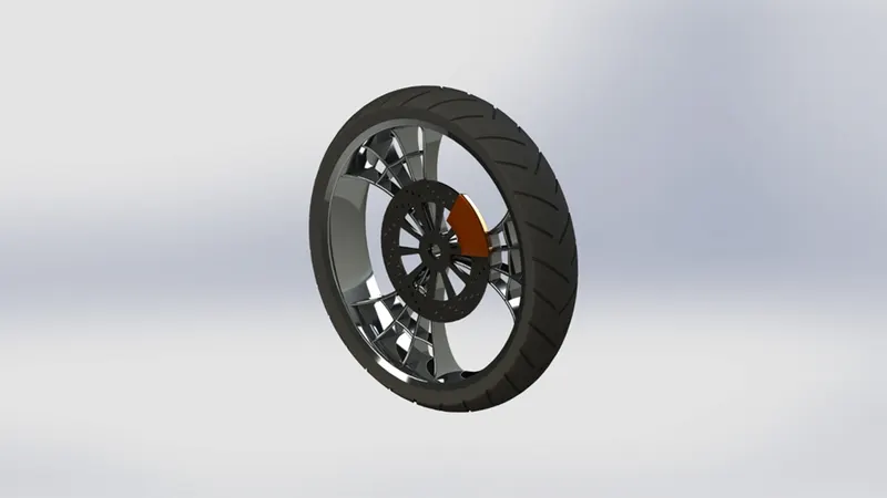
8. Front Wheel:-
- The Front Wheel helps to move the vehicle.
- It consists of Rim, Rotor, Calliper, Tyre
- By using tools like Revolve Boss, Trim Entities, Fillet, Extrude Bose, Revolve Cut, circular Pattern, Chamfer, Extrude cut, Appearance, etc.
Part Model Image
Render Image
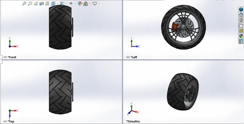
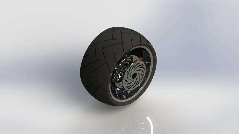
9. Rear Wheel:-
- The Rear Wheel also helps to move the vehicle.
- It consists of Rim, Rotor, Sprocket, Calliper, Tyre
- By using tools like Revolve Boss, Trim Entities, Fillet, Extrude Bose, Revolve Cut, circular Pattern, Chamfer, Extrude cut, Appearance, etc.
Part Model Image
Render Image
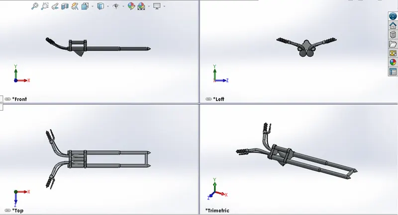
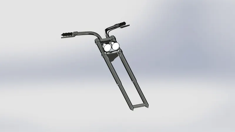
10. Front Fork:-
- The Front Fork is used to hold the Front Wheel with contain the headlight and Handel bar.
- It helps to give the direction to the bike.
- By using tools like Extrude Boss, Trim Entities, Revolve boss, Split, Move Bodies, Copy Bodies, Dome, Mirror, Combine, Projected Curve, Sweep boss, Appearance, etc.
Part Model Image
Render Image
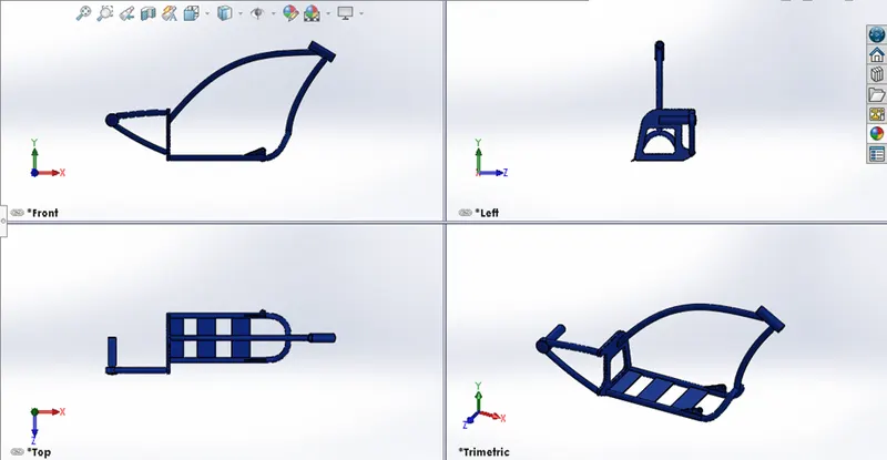
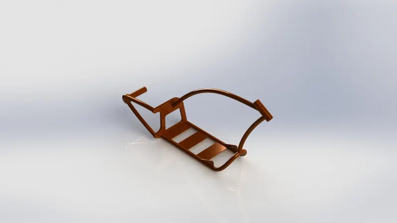
11. Chassis:-
- The Chassis is the back bone of the vehicle, it gives the vehicle strength and ability to handle well
- The major components like engine, pedal, Rear Wheel, Front Fork etc.
- By using tools like Offset Entities, Convert Entities, Projected Curve, Trim Entities, Sweep boss, Split, Revolve cut, Extrude boss, Fillet, Combine, Appearance, etc.
Part Model Image
Render Image
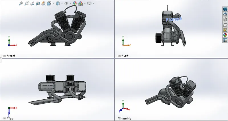
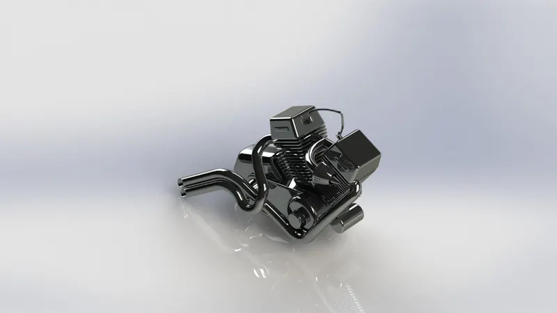
12. Engine:-
- The Engine is use to create mechanical energy for move the bike.
- By using tools like Trim Entities, Revolve boss, Extrude cut, Offset entities, Dome, Fillet, Projected curve, Sweep boss, Mirror, Circular pattern, Split, Appearance, etc.
Part Model Image
Render Image
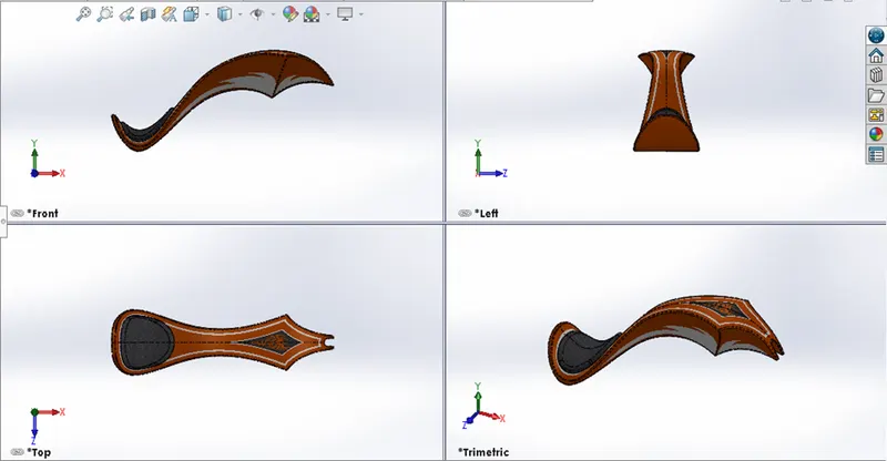
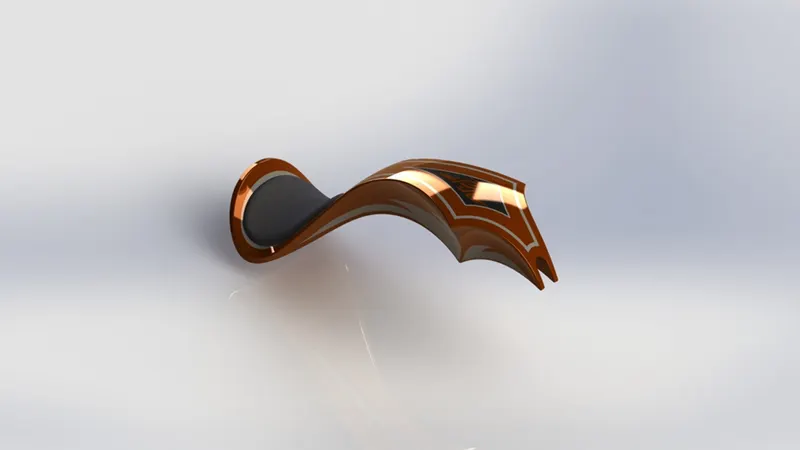
13. Gas Tank:-
- The Gas Tank is used to storage of fuel for the bike
- By using tools like Trim Entities, Projected Curve, Sweep boss, Loft Surface, Knit Surface, Sweep cut, Fillet, Shell, Appearance, etc.
Part Model Image
Render Image
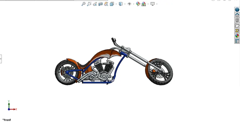
Assembly of American Chopper:-
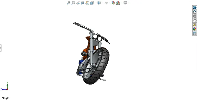
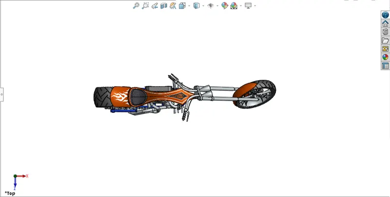
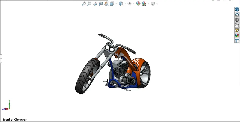
- Putting all the components together in an assembly line with accurately to create the complete product that performs as required.
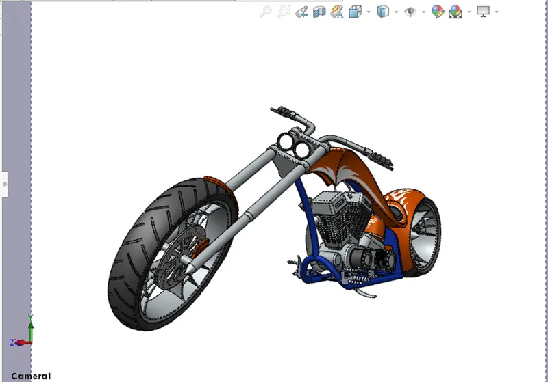
- After assembly we will create the camera view.
- After finish the camera view we will render the American Chopper by using Photoview 360 for a realistic view.
Front View
Side View
Top View
Fronr od Chopper View
Camera View
Render View using Photoview 360
View 1
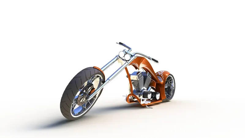
View 2
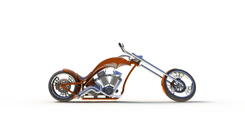
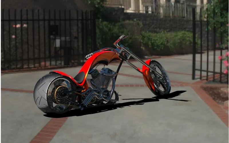
Render by using Solidworks Visualize
Fig 1
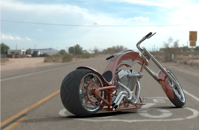
Fig 2
Conclusion:-
By complete the American Chopper we learn solid and surface Modeling features, photoview 360, Solidworks Visualize