Advanced Sheet Metal Design Using NX Cad Challenge_1_Casing Design
Title of the Project:-
Advance sheet metal design using NX cad Challenge 1 Casing Design
Objective:-
To design a Sheet metal Casing design using Siemens NX cad sheet metal application
Introduction:-
Sheet Metal – It is formed by an industrial process into thin, flat pieces which is mostly used in Machinery, Automotive, Aerospace, Agriculture, Mining, Shipping industry, etc. The thickness of Sheet Metal is in between 0.25 mm to 6 mm. There are many types of sheet metals available, e.g – Alloy Steel, Stainless Steel, Carbon steel, etc.
NX cad – It is normally known as “UNIGRAPHICS”. It is an advanced CAD software which is owned by Siemens. This software is used for Design, Analysis, manufacturing.
Design Methodology:-
Description:-
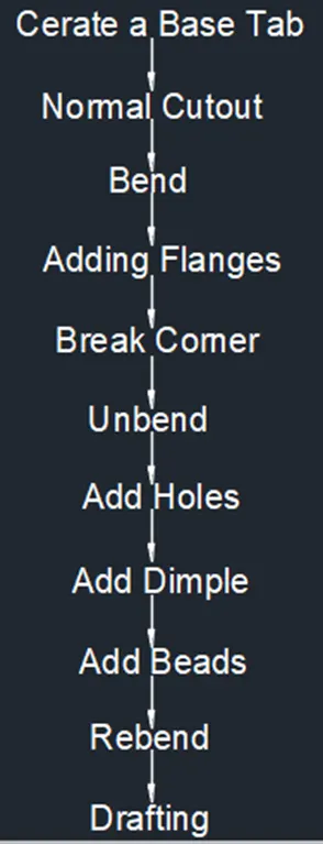
Commands are used to complete the Model
Sketch – By using this command we can draw a 2D model.
Tab – By this command we can add a parameter to the 2D model.
Bend – By this command we can bend the tab at a particular position with reference.
Flange – By this command we can extend sheet metal through the edges of the tab.
Unbend – By this command we can flatten the 3D model by selecting one face as a stationary face.
Hole – By this command we can create a hole on the surface of sheet metal.
Dimple – By this command we can create a particular shape by sketching with certain depth.
Bead – By this command we can give strength to a sheet metal at a particular shape at a certain point.
Mirror – By this command we can mirror the feature as required.
Rebend – By this command we can flatten the sheet metal.
Flat Pattern – By this command we create a flat pattern feature from the formed sheet metal part.
Procedure:-
First draw the sketch as per dimension, then make it tab. Then do the next sketch by selecting the plane as required and give the dimension as required. Then do the normal cutout.
Then draw 2 symmetric line as per the dimension then do Bend operation. After do the break corners as per dimension. Then unbend the sheet metal.
Draw the points as per drawing and add the hole on the points with its dimension.
For dimple operation draw the sketch by selecting the plane, after that do the spline then do move curve as per dimension. After complete the sketch do the dimple as per dimension.
For the bead operation we will draw the circle as require dimension then we will do bead. After complete the bead operation we will mirror this through the axis as per required. After that we will rebend the sheet metal.
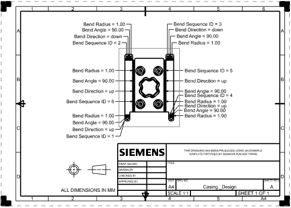
For draft the drawing we will flat the component and draft it on an A4 size sheet.
Model Views:-
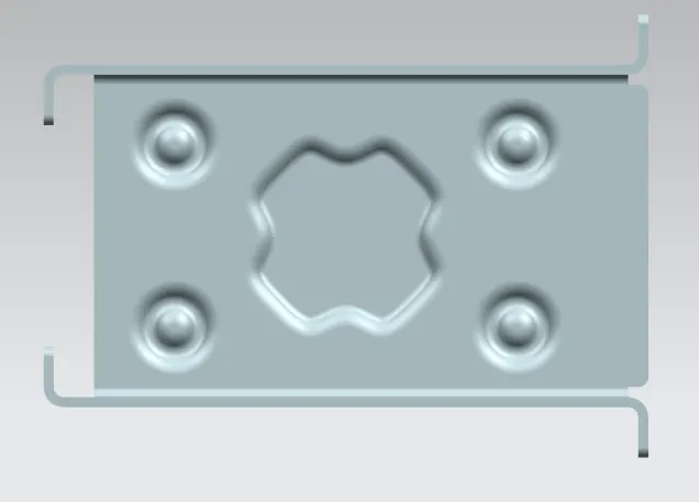
Top View:-
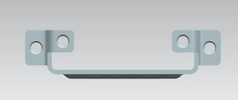
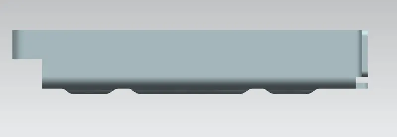
Side View:-
Front View:-
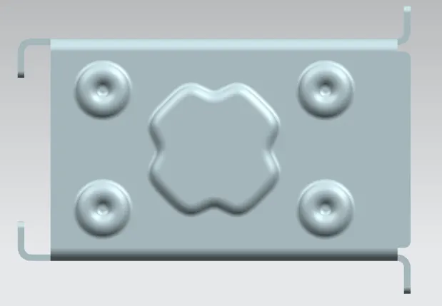
Bottom View:-
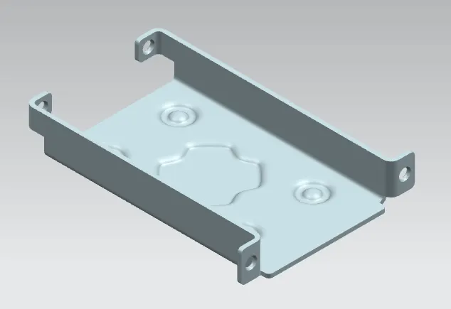
Isometric View:-
Drafting:-