Photo Realistic Rendering
1. REPORT ON ASSEMBLY OF CHOPPER MODEL
DESIGN OF AMERICAN CHOPPER USING SOLIDWORKS
2. OBJECTIVE
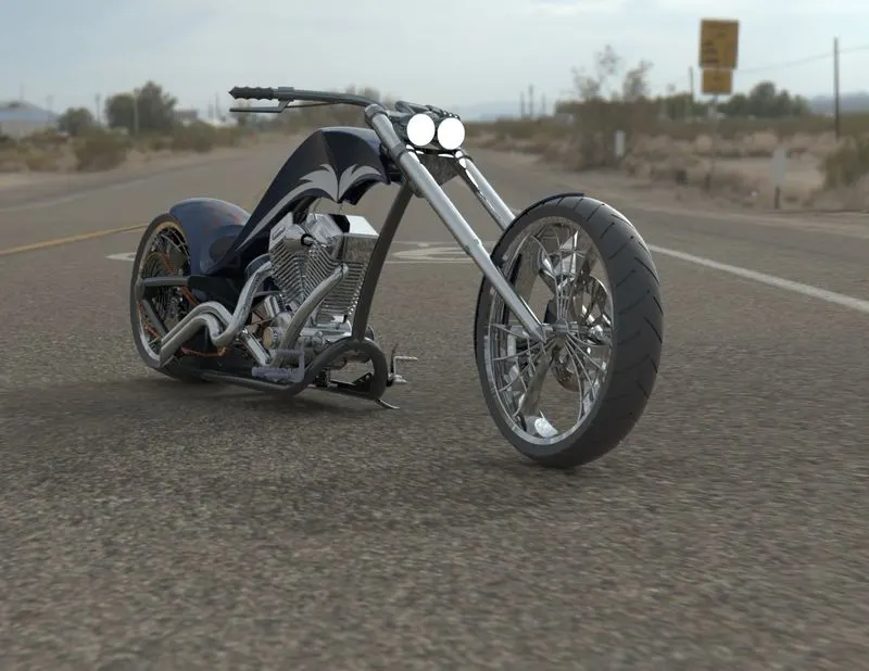
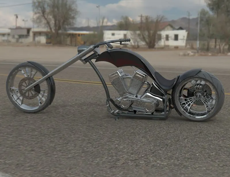
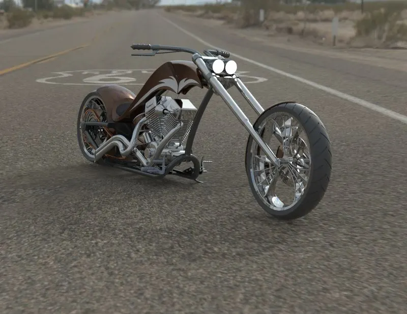
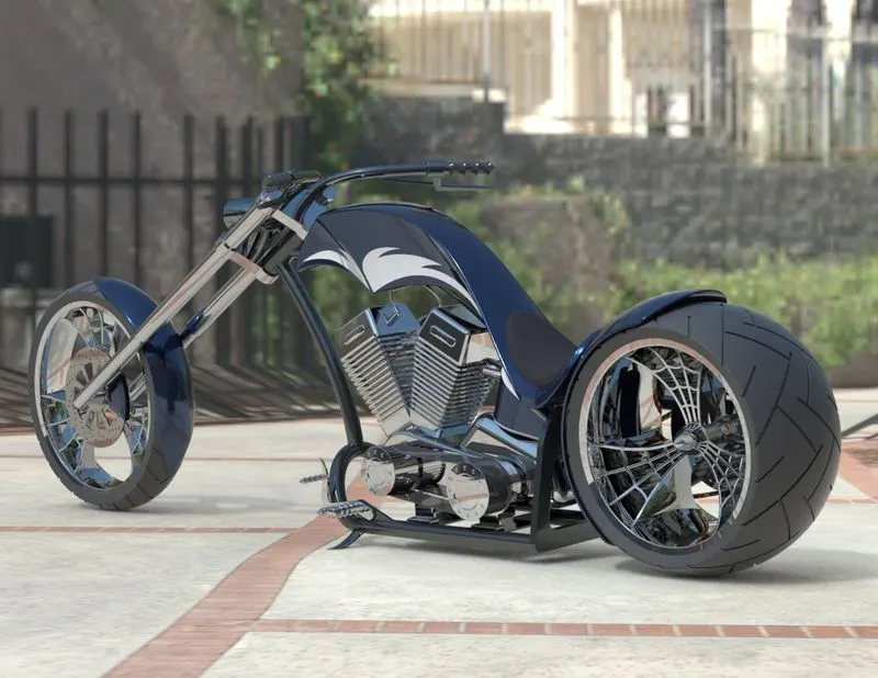
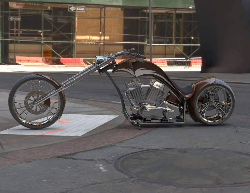
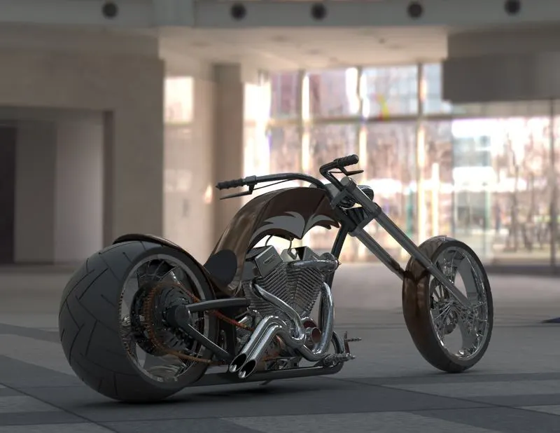
The objective of the project is to model an AMERICAN CHOPPER using CAD (computer-aided drafting) software-SOLIDWORKS and to render it with SOLIDWORKS visualize to create a photorealistic view of it.
3. INTRODUCTION
This project explains the design of American Chopper using the CAD software SOLIDWORKS from sketching the parts and modelling them to the final rendering of the assembly to give a photo-realistic view.
4. METHODOLOGY
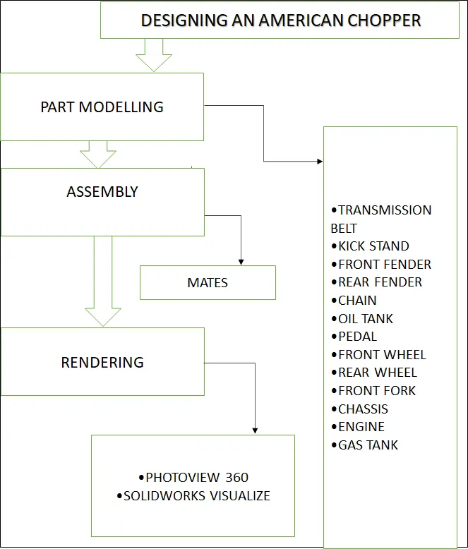
- Part Modelling
- Assembly
- Rendering
FLOW CHART
5. PART MODELLING
In part modelling first, the 2D sketch of the part is sketched using the tools in the sketch tab and then the 2D sketch is converted into a 3D part using the features in the feature tab.
FEATURES USED
Boss Extrude: This feature is used to expand the object in 3D according to the sketch plane.
Extrude Cut: Extrude cut feature is used to cut/remove the 3D object in a linear path according to the sketch.
Fillet: Fillet is a feature used for making round internal or external edges to avoid sharp edges and make them smooth.
Loft Boss/Base: The loft boss is a feature used to achieve Complex Shapes. It does this by interpolating surfaces between various Cross-sections of a model. These cross-sections can be sketches, faces, or edges.
Split: The split tool is used to split a single solid part into two solid parts. It is used to project an entity onto other surfaces or curved/planar faces.
Dome: Dome is a feature used to make dome-shaped extrude including an elliptical dome.
Shell: Shell feature is used to make hollow space in the solid part by selecting the outer wall of the solid part and so removes the inner parts. It is also used to reduce the specific thickness.
Combine: combine tool is used to make integration of two solid parts which intersect each other as the same solid part.
Chamfer: Chamfer is used to make a sharp edge or corner slightly tapered rather than being a perfect square.
Linear Pattern: The linear parent is used to create a different number of instances required to create the pattern linearly.
Curve Driven Pattern: Curve driven pattern is used to make any pattern followed by the curve is sketched before.
Circular pattern: Circular pattern is a feature used to make 3d feature into a circular pattern according to the number of insistence.
Revolve boss base: Revolve feature is used to make cylindrical or circular 3D extrude along with a given reference axis as per drawn sketch.
Revolve cut: Revolve cut is used to cut or to reduce the extrude of a cylindrical round surface.
Move/copy body: This feature is used to move/copy the 3D body from one place to another place.
Mirror: Mirror is used to mirror a feature or body by reference to the selected plane
Sweep: This feature is used to sweep any kind of fully defined sketch along with the path.
Sweep cut: Sweep cut is the same as sweep feature but it's directly proportional to sweep which makes a cut along the sweep path.
Swept Surface: It is used to make a surface along with a path the curve is driven.
Boundary Surface: Boundary surface is used to make a surface in between two finished surfaces.
Loft Surface: The loft surface is used to make a loft in between two profiles along with a guide path.
Knit surface: Knit surface is used to knit the two free edges or open edges of the surfaces together also reduces the gap between the two edges of the surface.
Surface Trim: Primarily used to cut away material from a surface, and provides two modes: Standard and Mutual.
Projection Curve: Projection curve is a 3D curve that is projected on the basis of the two different 2D curves in two different planes.
Blocks: You can make save, edit and insert blocks from the drawing items and sketch entities that you use often such as standard notes, title blocks, label positions and so on you can attach blocks to geometry or to drawing views
Trim entities: it is used to trim the unwanted lines or extended entities in the sketch.
Appearances: An appearance defines the visual properties of the model including colour and texture. Appearances do not affect physical properties which are defined by materials. every material is assigned a default appearance.
ASSEMBLY
Assembly is most often referred to as putting components together in an assembly line, but more specifically, it refers to creating a complete product that performs an intended function. Changes in the component are automatically reflected in the assembly i.e. The rebuild option will automatically take place or else it will ask the user to rebuild the document.
ASSEMBLY APPROACH IN SOLIDWORKS
- Top-Down Approach
- Bottom-Up Approach
Rendering:
Rendering or image synthesis is the automatic process of generating a photorealistic or non-photorealistic image from a 2D or 3D model using a computer program. The resulting image is referred to as the render.
Major Categories in Rendering:
- Real-Time Rendering
- Pre-Rendering
Software Used:
- Photoview 360
- Solidworks Visualize
Components Designed:
- Transmission Belt
- Kick Stand
- Front Fender
- Rear Fender
- Chain
- Oil Tank
- Pedal
- Front Wheel
- Rear Wheel
- Front Fork
- Chassis
- Engine
- Gas Tank
Description:
Transmission Belt:
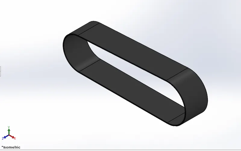
Features used
- Offset entities
- Extrude boss
- Fillet
- Appearances
This transmission belt is designed to adapt to the two pulleys created on one side of the engine block. It is a simple model created using very fewer tools like line, curve and extrude boss/base.
Kick Stand:
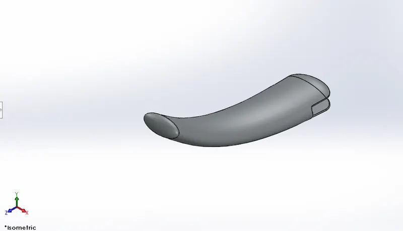
Feature used
- Loft boss
- Extrude boss
- Extrude cut
- Dome
- Split
- Fillets
- appearance
Kickstand for this bike is of a very simple kind made by the application of the sweep feature. An opening is kept for it to fix it to the chassis and the Dome is applied at the ends of the kickstand.
Front Fender:
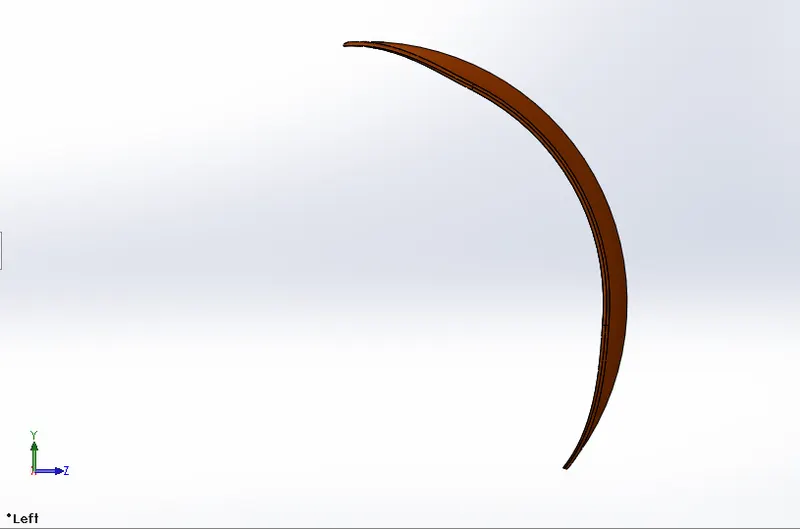
Features used
- Offset entities
- Trim entities
- Revolve boss
- Dynamic Mirror
- Split
- Appearances
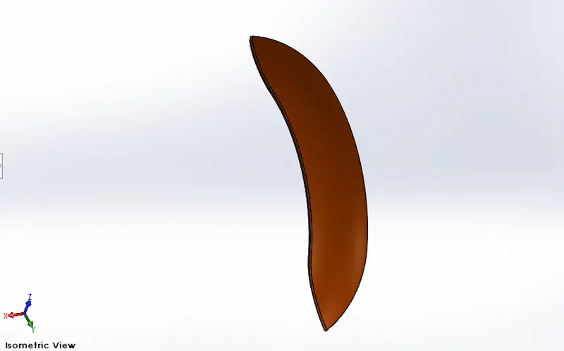
The front fender for this bike is designed simply by revolving the cross-section and cutting away material at the end to make it pointed. Revolve and split tools are the most used tools here.
Rear Fender:
Features used
- Offset Entities
- Trim Entities
- Revolve boss
- Appearances
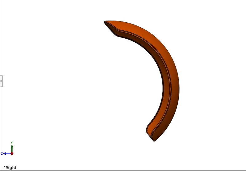
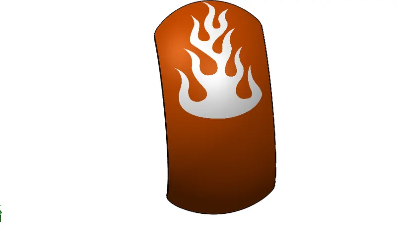
The rear fender is thicker but shorter compared to the front fender. It doesn't have a pointed end like the front fender, rather a rounded end as in the Idea of the sketch. Revolve and split tools are the most used tools here.
Chain:
Features used
- Trim entities
- Fillet
- Blocks
- Extrude boss
- Linear Patterns
- Appearances
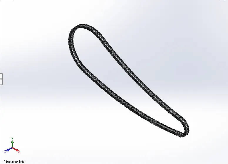
It is the most complex part of the whole design project. It consists of 390 bodies including separate bodies for all the inner plates, outer plates, and pins. The major feature used in this part is the Curve driven pattern which allows each instance of chain parts to follow the curve drawn initially for the chain. It is essential to keep all the elements of this chain as a separate body because it has to rotate along the curve and around the sprocket which is not possible if it is merged to make a single body
Oil Tank:
Feature used:
- Boss Extrude
- Combine
- Fillet
- Shell
- Appearance
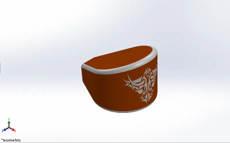
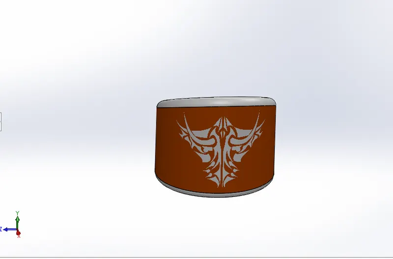
The oil tank is placed above the engine block which is also made hollow inside. Extrude and shell are the major features used in this part.
Pedal:
Features used
- Extrude boss
- Fillet
- Linear pattern
- Dome
- Chamfer
- Appearance
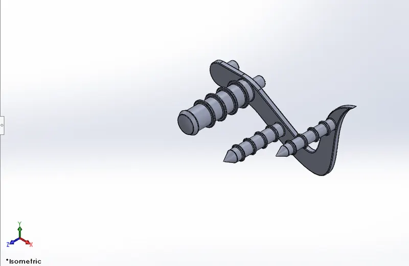
There are two pedals, left and right. Among them, only the right pedal was sketched and designed in the part design environment and the left was made using the in-context features of the assembly environment. It is designed to sit into the holes provided at the bottom of the chassis on both sides.
Front Wheel:
Features used
- Revolve boss
- Trim entities
- sketch fillet
- Boss Extrude
- Revolve Cut
- Linear Pattern
- Chamfer
- Cut Extrude
- Circular Pattern
- Appearance
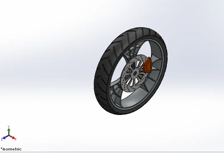
The front wheel is thinner than the rear wheel. It is designed to be a multi-body part consisting of the rotor, sprocket, rim, tire, and calliper all are made to be single bodies. Mostly used features include revolve, extruded cut, and circular pattern.
Rear Wheel:
Features used
- Revolve boss
- Trim entities
- Fillet
- Extrude Boss
- Planes
- Revolve cut
- Linear pattern
- Chamfer
- Fillet feature
- Extrude Cut
- Circular pattern
- Appearance
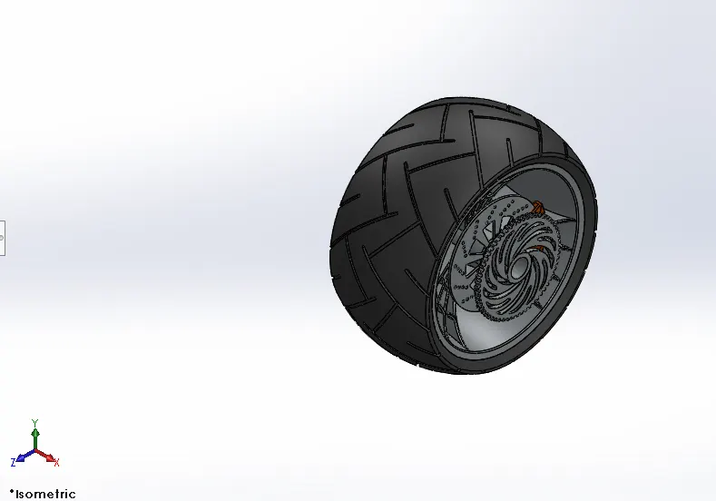
The rear Wheel is much thicker than the front wheel. Just like the front wheel, it is also designed to be a multi-body part consisting of the rotor, sprocket, rim, tire, and calliper all in a single part. Mostly used features include revolve, extruded cut, and circular pattern.
Front Fork:
Features used
- Extrude boss
- Trim entities
- Revolve boss
- Split
- Move/copy bodies
- Dome
- Mirror
- Combine
- Projected curve
- Sweep boss
- Appearance
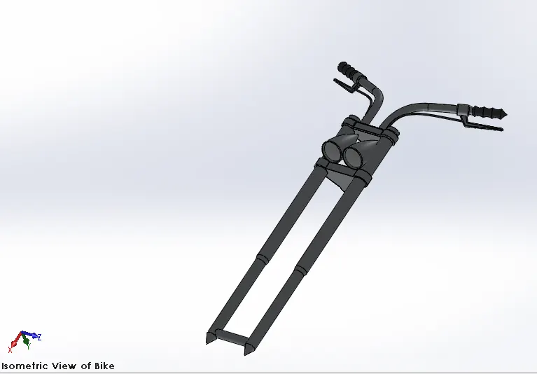
It is the most unique part of this American Chopper bike. It is longer than usual bikes and the angle is extremely low with respect to the horizontal. The handles are shorter and are customized according to their comfort. For this model, revolve features is mostly used. It consists of two headlights
Chassis:
Features used
- Offset entities
- Convert Entities
- Project Curve
- Trim entities
- Sweep boss
- Split
- Revolve Cut
- Extrude boss
- Fillet
- Combine
- Appearance
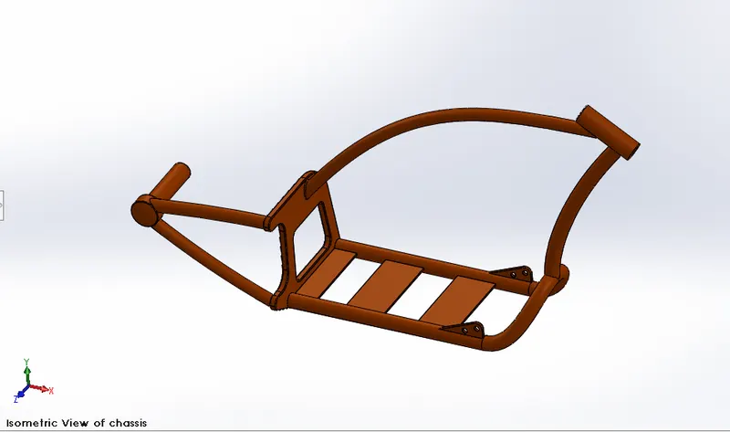
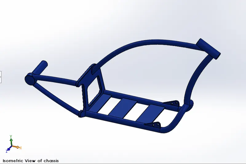
The chassis is the frame that bears most of the load on the bike. In the design process of this chassis, the mostly applied features are splines, sweeps, project curves, split, etc. The lower tube is mirrored with respect to the mid-plane. The rear plate supports the rear arm which holds the hub from only one direction so it is designed to be stiff enough.
Engine:
Features used
- Trim entities
- Revolve Boss
- Extrude Cut
- Offset entities
- Dome
- Fillet
- Projected Curve
- Composite Curve
- Sweep boss
- Mirror
- Circular pattern
- Split
- Appearance
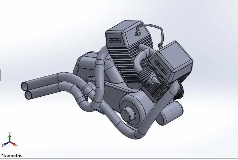
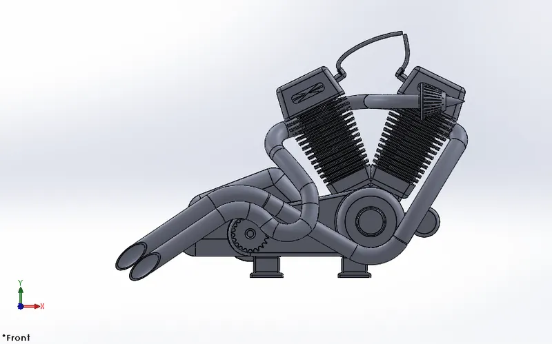
The engine used in this bike is a V engine with two exhaust pipes. Although it is the solid modelling of the engine block, it covers most of the aspects of the engine block. It incorporates the cooling fins, spark plug representation, intake and exhaust manifolds, transmission unit with the transmission belt, and pulleys.
Gas Tank:
Features used
- Projected curve
- Trim entities
- Sweep boss
- Loft surface
- Knit surface
- Sweep Cut
- Fillet
- Appearance
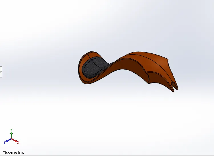
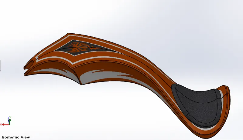
The fuel tank for this American Chopper is designed as per the info sketch. It is hollowed out to make a tank for the fuel inside. The most applied features include extruding surface, boundary surface, shell, and knit surface. Sienna is assigned as its appearance and decals are applied.
Assembled American Chopper:
Assembly is most often referred to as putting components together in an assembly line, but more specifically, it refers to creating a complete product that performs an intended function. Changes in the component are automatically reflected in the assembly i.e. The rebuild option will automatically take place or else it will ask the user to rebuild the document.
6. American Chopper of the Various Views:
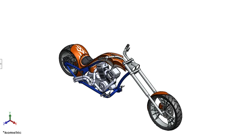
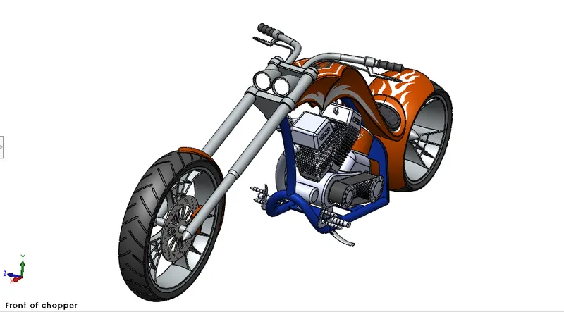
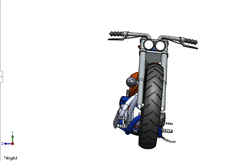
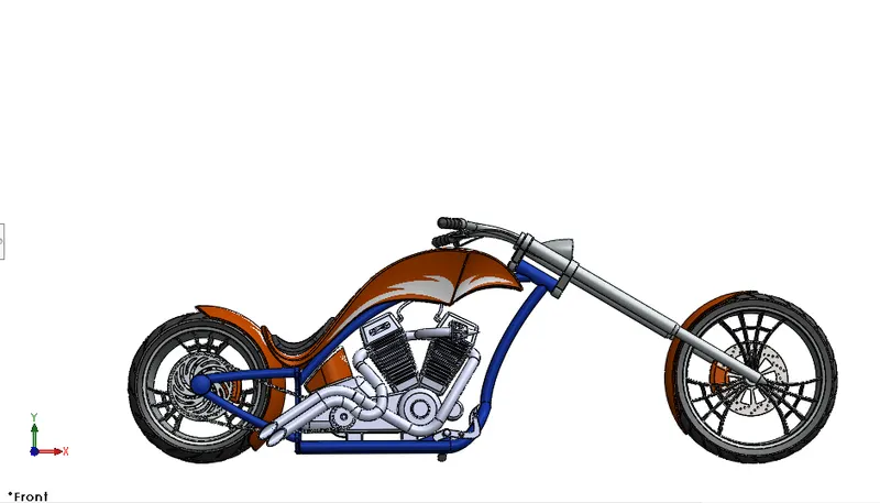
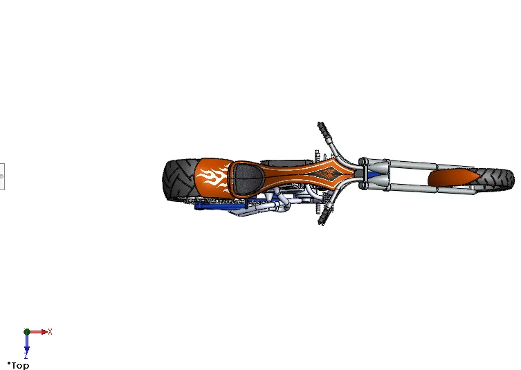
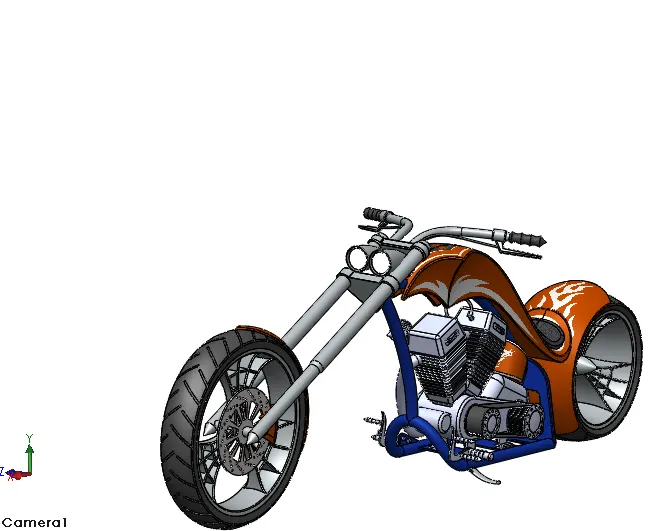
The American chopper is assembled using the feature called mates. Each and every part is mated with the other or the base part with specific relation. Some relations that are used to mate the parts of American chopper are mentioned below,
- Concentric
- Coincident
- Parallel
- Tangent
- Width
Final Render of American Chopper:
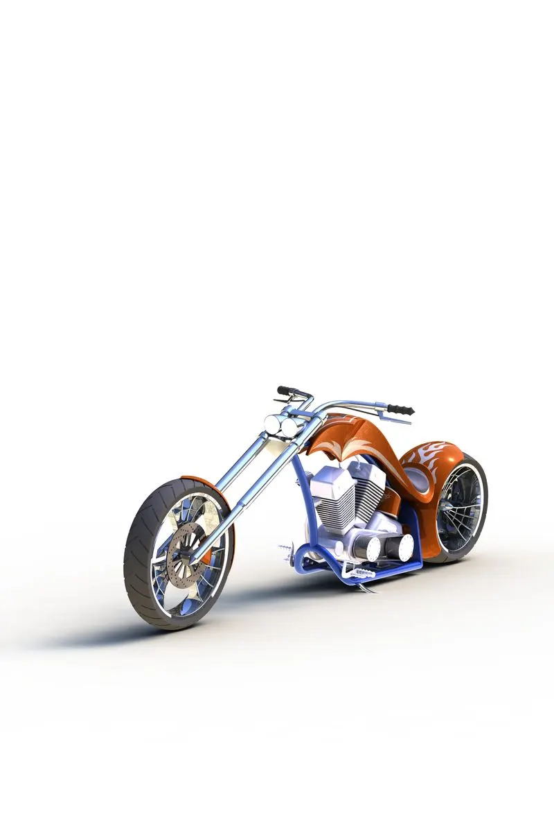
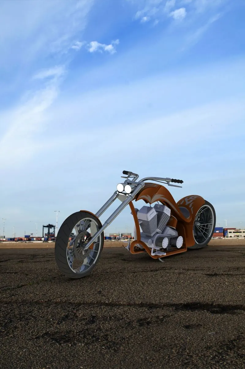
CONCLUSION
Thus, the parts of the AMERICAN CHOPPER are designed and assembled using SOLIDWORKS and are rendered to photorealistic images using PHOTO VIEW 360 and SOLIDWORKS VISUALIZE.