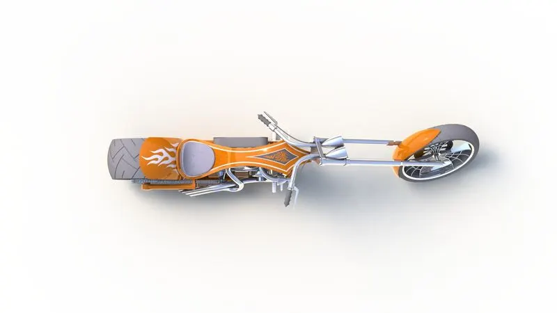
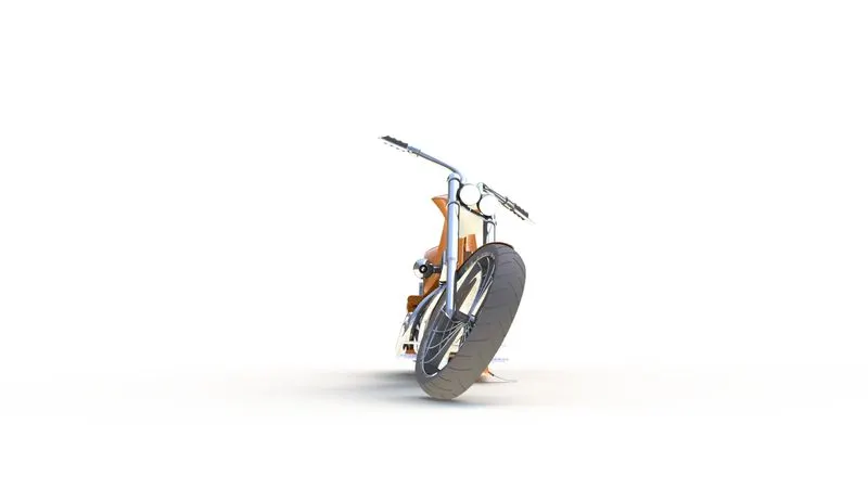
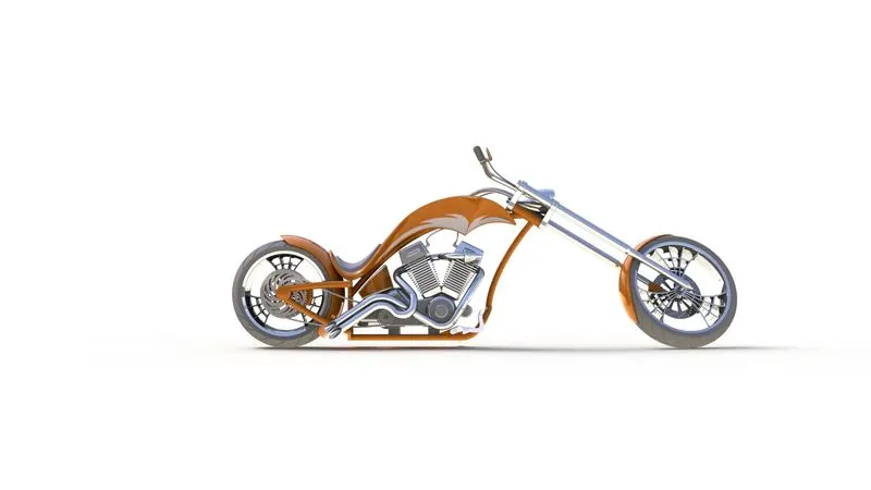
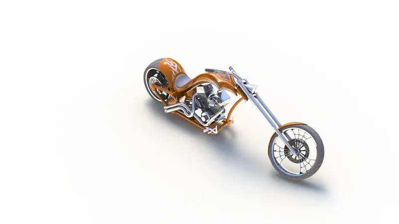
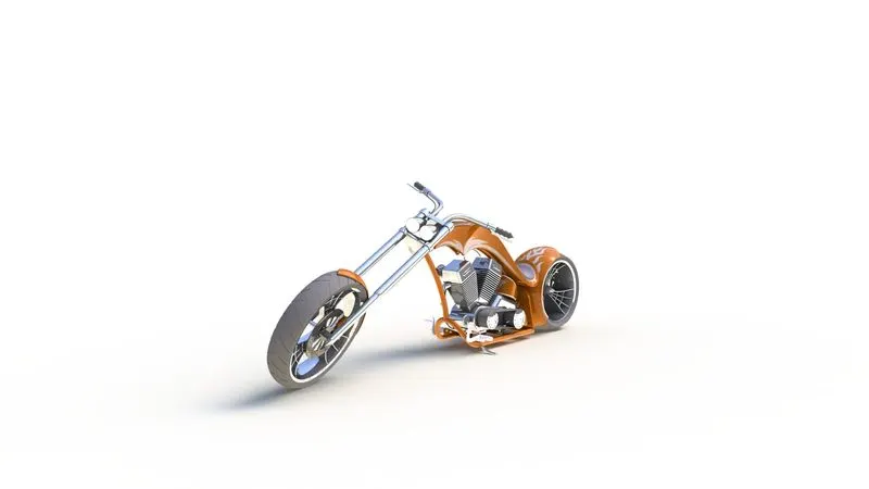
Photo Realistic Rendering
1. REPORT
MODELLING OF AMERICAN CHOPPER ON SOLIDWORKS
INTRODUCTION
In the process of completing this project i.e., the design of American chopper assembly by using SOLIDWORKS, we got to learn about different commands and tools for 2d-sketching and then converting them to part model by using 3d
Modeling tools. After completion of designing the necessary part models we gone for assembly of chopper. After proper assembly we finished our chopper by adding decals, lights, cameras and then go for rendering to get finished chopper.
The components that we have designed for chopper are:-
- Chassis
- Engine with exhaust
- Front wheel and Rear wheel with rims and sprocket calipers
- Front Fork
- Front and Rear Fender
- Oil Tank
- Chain and Transmission Belt
- Kick Stand and Foot Pedal
OBJECTIVE
- Learning the tools and commands of solidwork.
- Designing different parts of chopper with the help of Blueprint and given dimensions.
- Assembling the designed parts to form a chopper.
- Learning the adding of decals, lights and cameras angles for better visualization.
- Using photoview 360 which is helpful for setting the image quality and getting realistic view.
- By using solidworks visualization software we finally go for rendering our American Chopper.
DESIGN APPROACH
There are two basic types of design approach in designing procedure i.e.,
- Bottom-up approach 2. Top-down approach. In this project we have used Bottom-up approach.
- Bottom up approach: The typical way is to design from the bottom up. Parts are designed and modeled first, then inserted into an assembly and positioned with mates. You must modify each part individually to change it. The assembly then reflects these adjustments.
- Top down approach: The Top down approach is an assembly-centric modeling. One or more features of a part are determined by anything in an assembly, such as a layout drawing or the geometry of another part, in top-down assembly design. The design intent starts at the top with the assembly and works its way down to the parts.
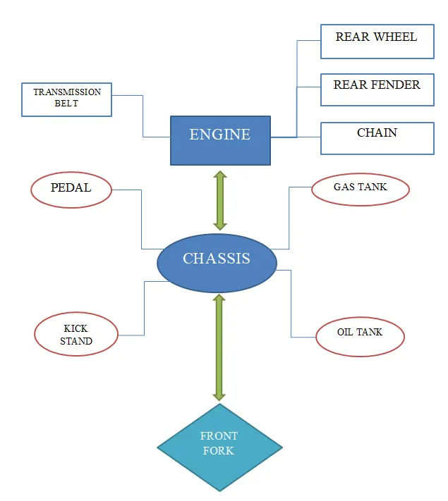
The different types of tools and commands we used for modeling different parts of American chopper in this project are:-
- Boss Extrude
- Fillet
- Revolve Boss
- Reference Geometry
- Extrude cut
- Shell
- Pattern
- Mirror
- Projected curve
- Knit
- Mate
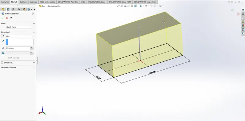
BOSS EXTRUDE
It is useful to convert 2d closed sketch or profile to 3d solid model. While using this feature we can use different input types and values as per the need of the required part. There are multiple direction options i.e., Blind, midplane, from the vertex, up to next etc.
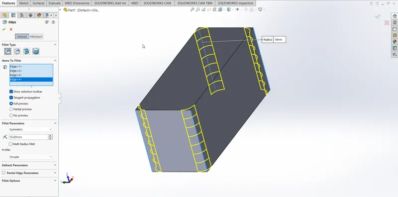
FILLET
This tool is very helpful while creating curved or rounded edges. As we create solid part it has some sharp edges to make it curved we use fillet tool. We need to assign the desired radius values to the edges to be curved and there is few more option for selection of edges which helps to make the process easier.
REVOLVE BOSS FEATURE
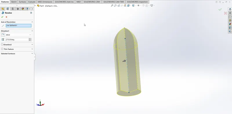
This Feature allows us to create solid body by revolving around the axis.
In this command we need to create sketch the need to be revolved and give centerline to make the sketch revolved around and we can also add the certain degrees the profile need to be revolved.
EXTRUDE CUT
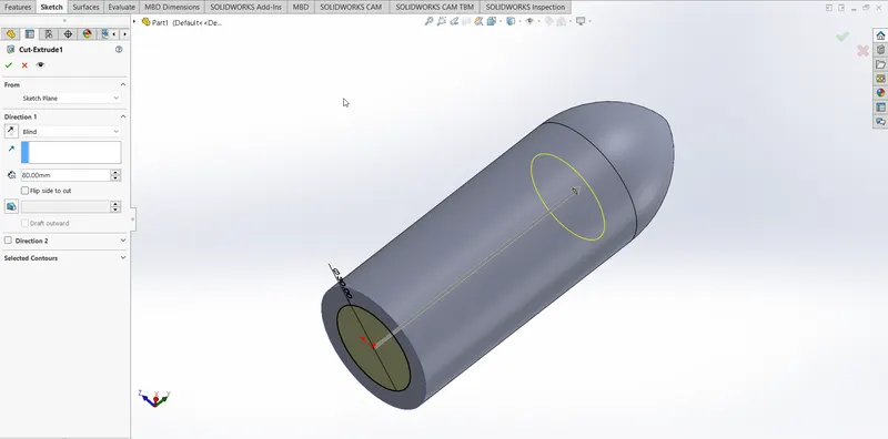
This feature is useful to cut-through or remove the unwanted material from the solid part and make the desired shape. We can use this tool by sketching the profile the way it’s needed to cut through the solid part and then opting the option extrude cut and selecting the sketch that will cut through and use few options which will be useful to make the as needed.
SHELL
This tool is useful for creating hollow shapes for solid body. In this tool we need to specify the thickness of the wall and the rest of the body will become hollow. This is useful to create containers, tanks etc. which are hollow from inside.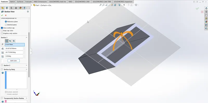
PATTERN
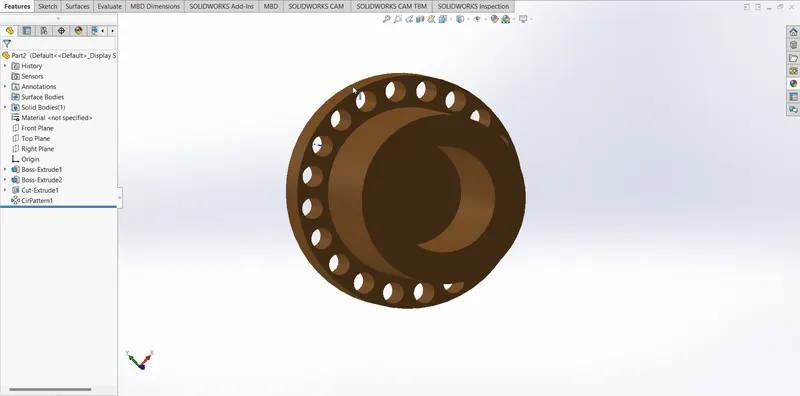
The pattern is used to repeat the same sketch multiple times throughout the part design. There are various types of pattern exists the most basic are linear pattern and circular pattern in which linear pattern patterns in given path and direction and circular pattern patterns around the axis and the degrees suggested.
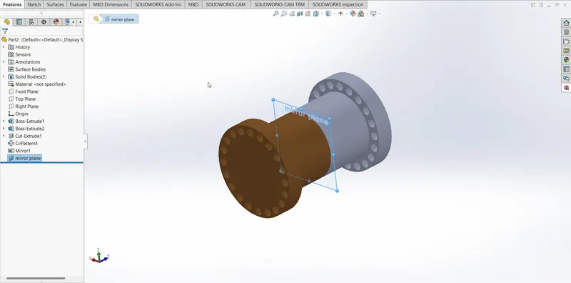
MIRROR
This tool useful to copy or replicate the solid part by using the plane, axis or face of the part that need to be replicated. It is very useful and saves time when we create part with similar dimensions.
REFERENCE GEOMETRY
This feature is frequent used for creating additional planes, co-ordinate system and axes as per the requirement of the geometry that we are designing. Ex. If the geometry needs reference axis pattern but we don’t have one by using reference axis we can create one which is helpful for pattern.
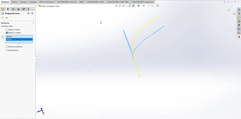
PROJECTED CURVE
When the Sketch demand for 3D profile it gets difficult to dram in 2D plane then the feature projected cure is useful to create 3D curve using two 2D sketches in two different planes. It makes easier to create complex curves using this feature.
KNIT
This tool is used to knit or combine multiple faces or surfaces into one make a single solid surface. When this option is used on a closed volume it generates solid body.
MATE
The most useful tool in assembly as it helps to join various parts of the body through different option and make a single body and it can also allow the degree of freedom to the selected parts. Few features mate are coincident mate, concentric mate, Tangent and angular mate. By using these relations we can mate the two parts and make them fix to each other.
These are the feature and tools we use in solid works to create part or body. By using these features we had developed American chopper in solid works.
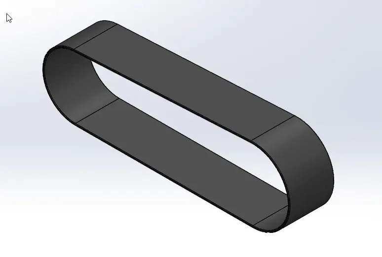
TRANSMISSION BELT
The transmission belt is used to transmit power with the help of belt and pulleys. We have given the belt material as rubber and created a solid body.
To create this we had used different features those are:
- Sketch
- Extrude
- Fillet
- Offset
- Appearance
KICKSTAND
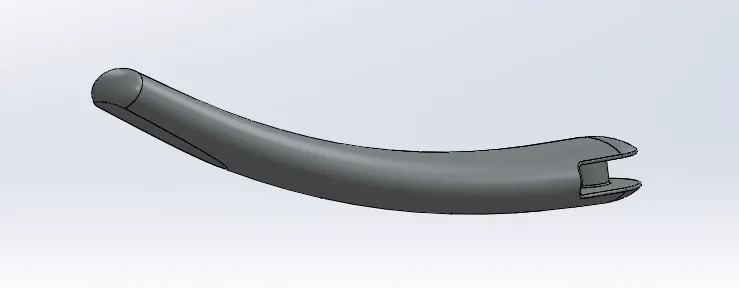
Kick Stand is designed by using reference plane and by using loft feature and then applying dome to both ends and using split to create flat surface at bottom of the kick stand. Chrome appearance is applied to kick stand.
The features used to design kick stand:
- Sketch
- Ellipse
- Spline
- Loft
- Reference Plane
- Cut extrude
- Split
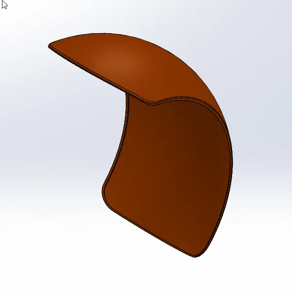
FRONT FENDER
This is designed by revolving the sketch around the axis and then removing the undesired material by using the split tool to achieve the desired shape for the front fender. Sienna appearance is applied to the front fender.
The feature used to design front fender:
- Sketch
- 3-Point arc
- Offset
- Revolve
- Split
- Fillets
- Appearance

REAR FENDER
It is mostly similar to the design of front fender. Only sides of rear fender are bit different from front fender. Sienna appearance is applied to Rear fender.
The features used to design Rear fender are:
- Sketch
- 3-Point arc
- Offset
- Trim
- Extend
- Revolve
- Split
- Fillets
- Appearance
OIL TANK
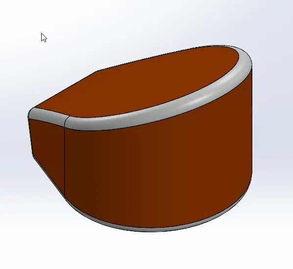
To design oil tank we had designed two differenr sketches on two planes and then combine them to attain the desired part for the oil tank. We have used shell command to make it hollow. Sienna appearance is given to Oil tank and white paint appeareance is given to fillets.
The features used to design oil tank are:
- Sketch
- 3-point arc
- Combine
- Fillets
- Shell
CHAIN LINK
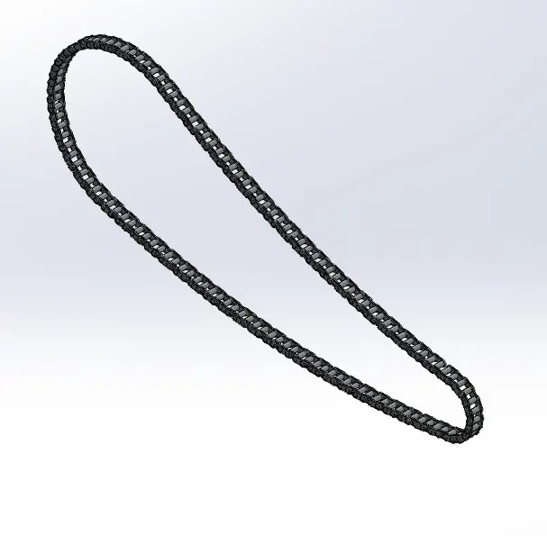
To design chain at first we profile of the chain. Then we design blocks and pins for the chain and use both pattern styles Lienar Pattern and Circular Pattern to create chain. Then we mirror the block and and pins to other side to create a chain. Chrome metal appearance is applied to the chain.
The feature used to design Chain link:
- Sketch
- Circles
- 3-Point arcs
- Slot
- Block
- Pattern
- Mirror
- Appearance
PEDAL
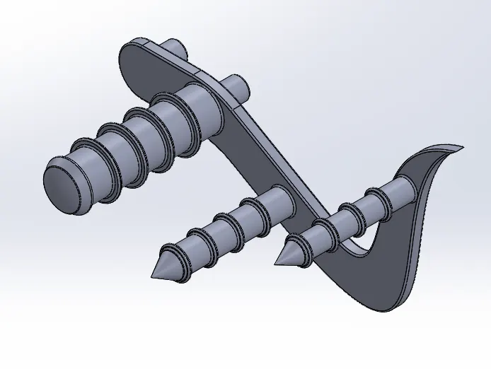
The pedal is a simple rigid part. To create this we have used splines and fillets and chrome metal appearance given to the pedal.
The features used to design pedal are:
- Sketch
- Circles
- Revolve
- Chamfer
- Fillet
- Linnear Pattern
- Appearance
FRONT WHEEL
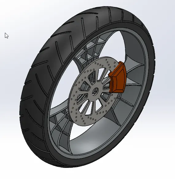
The front wheel is a combination Rim, Tire, Caliper and rotor. At first we had created Rim followed by created a tire around the rim. We used patterns to create rotor and by using midplane extrude we created caliper. The assigned appearances are rubber for tire, chrome for rotors and spokes and sienna for caliper.
The feature used to design front wheel are:
- Sketch
- Lines
- Sketch fillet
- Revolve
- Extend
- Trim
- Cut extrude
- Revolve cut
- Circular pattern
- Linear Pattern
- Chamfer
- Fillet
- Appearance
REAR WHEEL
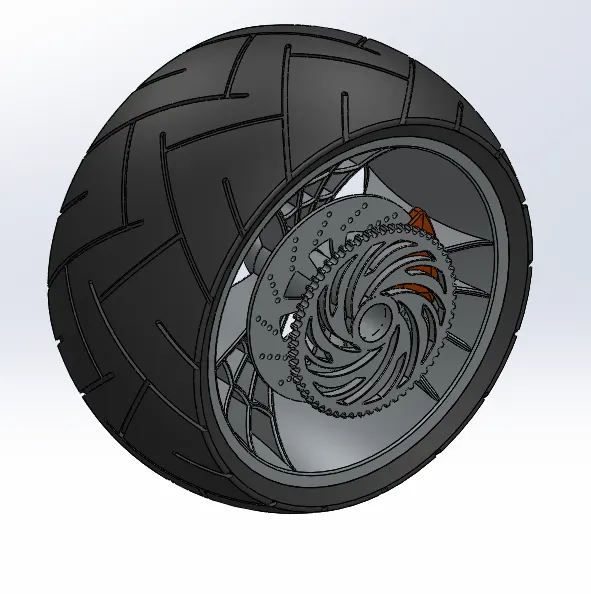
It is similar to design of front wheel. The components and functions are same only new component is added that is sprocket which will be connected to chain link. The appearances are also same and sprocket is applied with chrome metal.
The features used to design rear wheel are:
- Sketch
- Lines
- Sketch fillet
- Revolve
- Extend
- Trim
- Cut extrude
- Revolve cut
- Circular pattern
- Linear Pattern
- Chamfer
- Fillet
- Appearance
FRONT FORK
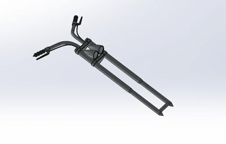
The front fork is combined with both chassis and front wheel. This function of front wheel is to provide suspension to the front wheel. The front fork is occupied with many parts like grips, clamps, forks, head lights and clutch levers.
In this design half part of the front fork and the rest half will be mirrored.
The features used to design front fork are:
- Sketch
- Line
- Revolve
- Fillets
- Linear patterns
- Projected curve
- Spline
- Reference planes
- Mirror
- Combine
- Dome
ENGINE
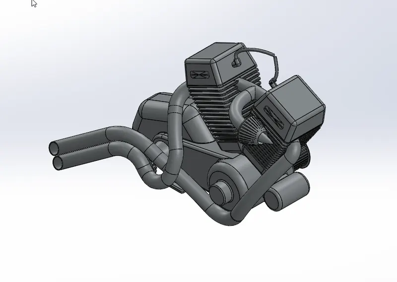
The most important component for any automobile is engine. It produces the required power to move the vehicle. To design the engine we have created fins, valves, exhaust, sprocket, air filter and engine casing. We made sure to fillet sharp edges of the engine. Chrome metal is used for appearance.
The features used to design engine are:
- Sketch
- Lines
- Circles
- Extrude
- Mirror
- Revolve
- Fillets
- Patterns
- Dome
- Cut Extrude
- Appearance
GAS TANK
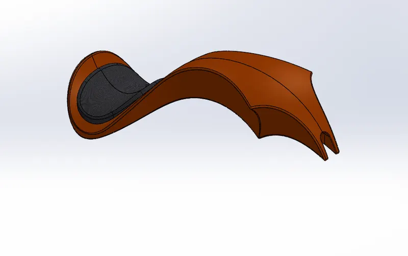
The gas tank is designed using surface design option. At first we designed half side of the gas tank and mirrored about the plane. By using knit option we made two different parts into single and the used shell command to make it hollow from inside. Sienna is added as appearance for gas tank.
The features used to create gas tank are:
- Blue Print sketch
- Spline
- Surface sweep
- Surface trim
- Surface loft
- Curve
- Mirror
- Surface knit
- Fillet
- Shell
- Appearance
CHASSIS
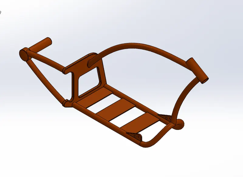
It is the base where every part will be placed. We have created the chassis using chassis reference from the blueprint. We have used feature like boss extrude. Fillet and revolve to create chassis. Sienna appearance is given to the chassis.
The features used to design chassis are:
- Blue print sketch
- Splines
- Curves
- Mirror
- Boss extrude
- Extrude cut
- Chamfer
- Split
- Revolve
- Combine
- Appearance
ASSEMBLY OF THE CHOPPER
In assembly we assemble all the designed parts to each other using mate command. At first we place chassis as every part we designed has get to mate with chassis only. After chassis is placed we import rest of the part one after and assemble the by using the mate command. For mating we have used several commands those are coincident mate, concentric mate, tangent or angular mate. The types mates used to join the parts are based on the common things of boyh the parts that are going to mate. After proper assembly we can check the alignment of the assembly using float. If any part coincides with each other then we can modify and make it perfect.
DECALS
Decals are very useful when we need to add any picture, design, photo or graphics to the part body it helps us to do so. In this we had added decals to rear tank, oil tank and gas tank of the American chopper.
RENDERING
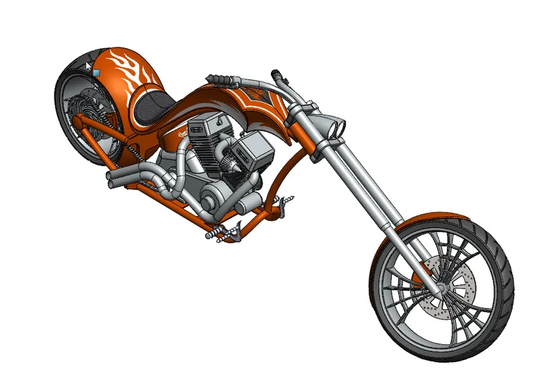
It is final step to get finished product which helps the design to look much realistic. For this we use photoview360 which helps us to adjust lights, cameras, scenes and appearance to the body. By adjusting these lights and cameras we can get desired views and increase or decrease the brightness of the chopper. We can use scenes to create realistic background. We also have to adjust resolution in options to get better photo quality and appearance.