Week 8 - Challenge 1 - Draft Analysis on a Fan Cover
DRAFT ANALYSIS OF FAN COVER
Draft Angle: It is rare to find the product without having draft angle. It is given to the side faces of the injection moulded part for easy ejections using ejection pin.
The class A surface of fan cover is provided to us:
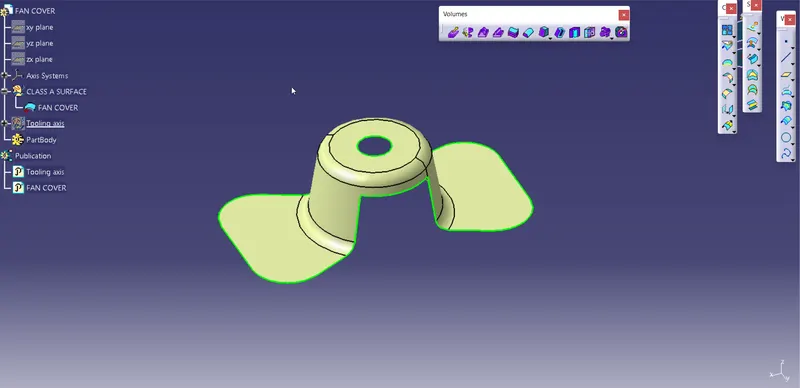
Fig.1: Class A Surface
At first we will check if there is any discontinuity in the class A surface designed. For the check we will use Boundary definition option to check the discontinuity in the surface.
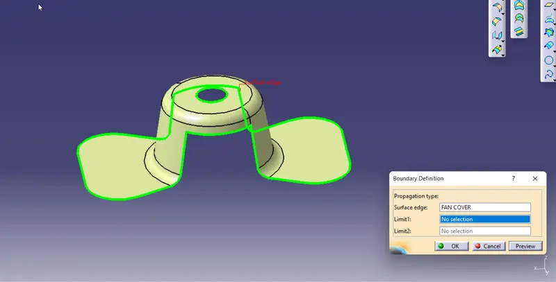
Fig.2: Boundary Definition
After analyzing the shape of the fan cover to provide tooling axis and try to minimize or avoid side cores as much as possible. For this surface we create dummy tooling axis in z direction by creating a point and datum axis at the point.
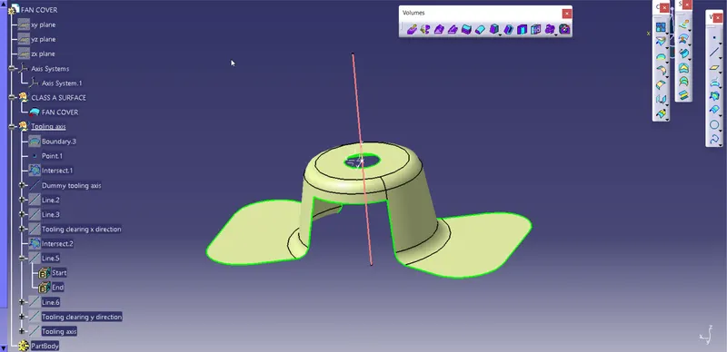
Fig.3: Dummy tooling axis
Now we create intersect on the XZ plane by using intersection definition command
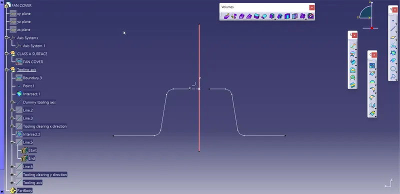
Fig.4: Intersection at XZ plane
After inspecting the intersection line we will find the parallel surfaces for the dummy axis line which may create problem while creating the component. Drawing the line through the parallel surfaces.
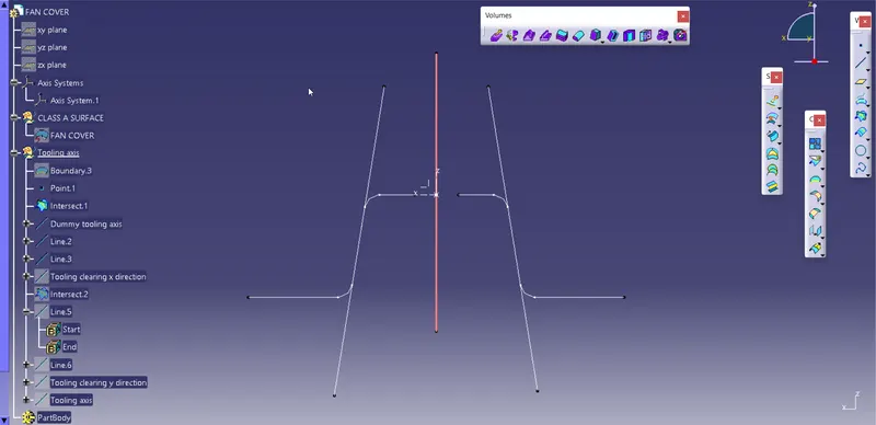
Fig.5:Dummy Tooling Axis
Now, using the bisecting line option we create a line between the parallel surfaces which will be the tooling axis in xz direction.
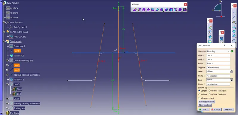
Fig.6: Bisecting Lines
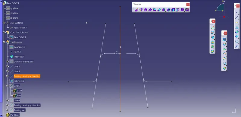
Fig.7:Tooling axis in xz direction
Now, creating the tooling axis for YZ direction using same steps as used in XZ direction.
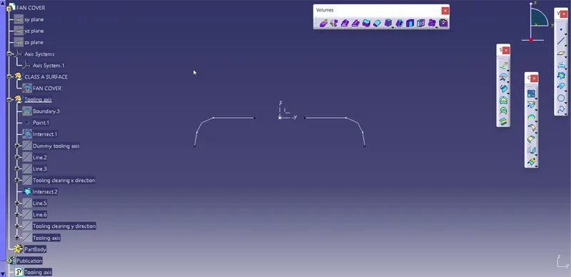
Fig.8 : Intersection at YZ plane
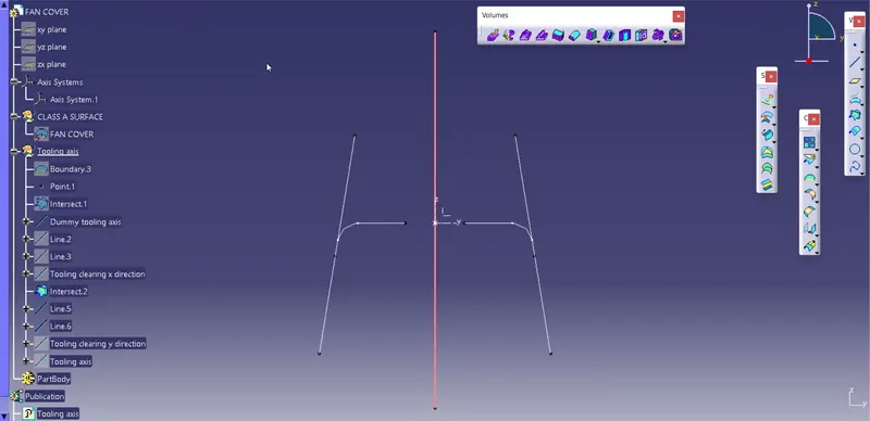
Fig.9: Extending parallel surface to dummy axis
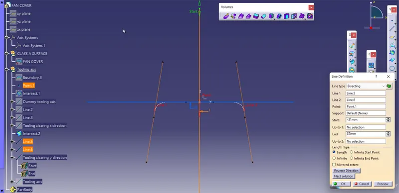
Fig.10: Bisecting Line
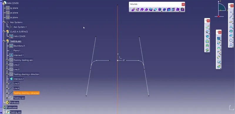
Fig.11: Tooling axis in YZ direction
As we have both the tooling axis in XZ and YZ direction we now bisect these tow line as per datum line to obtain the required tooling axis for the fan cover.
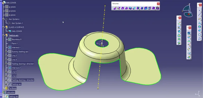
Fig.12: Tooling Axis
After preparing tooling axis we need to de draft analysis on the fan cover for that we need to enable by
Inset>Analysis>Feature draft analysis.
After enabling draft analysis we select compass option and put compass over tooling axis to get the required direction of draft analysis and then lock the draft direction.
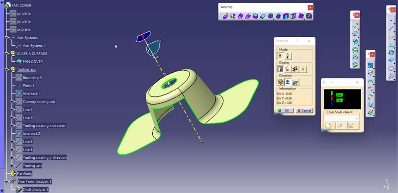
Fig.13: Compass on tooling axis

Fig.14: Draft Analysis Report
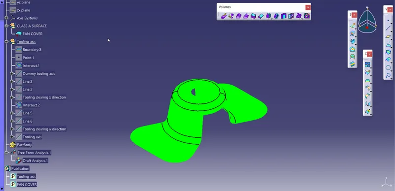
Fig,15: Isometric View
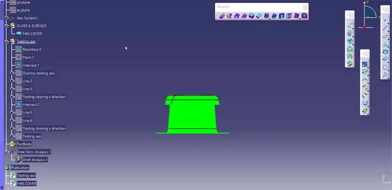
Fig.16: Front view
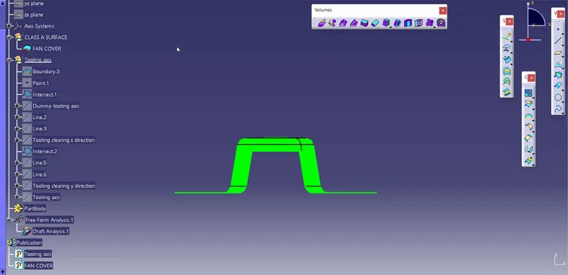
Fig.17:Side view
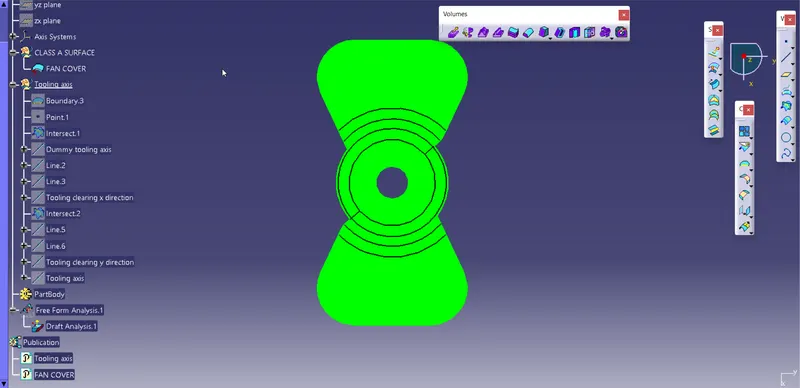
Fig.18:Top View