Door Arm Rest Week 8 Challenge
DOOR ARM REST
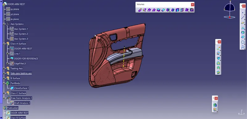
Fig: Door Arm Rest
At first we created the tooling axis for the given Class A surface by using its base;
- creating point
- creating Axis
- creating dummy axis at YZ and ZX axis using positioned sketch
- creating actual tooling axis by bisecting the two dummy axis.
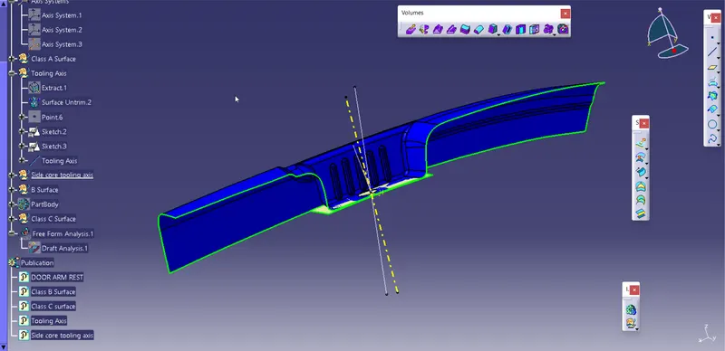
Fig: Tooling Axis
For the following given part we need one side core also for that we create another tooling axis in the similar way as main tooling axis.
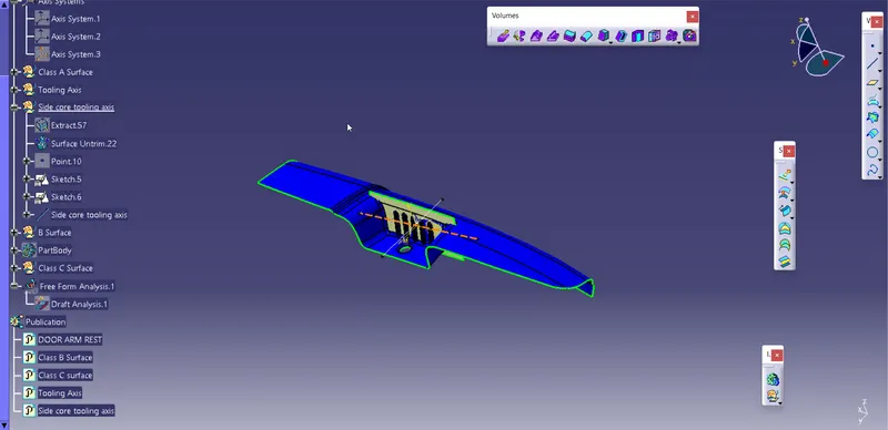
Fig: Side core tooling axis
Creating Class B Surface
At first we design front part of the component;
- Extracting the required faces
- untrim and extrapolate the extracted surface
- Offset it by 2.5mm and then provide fillet for the edge.
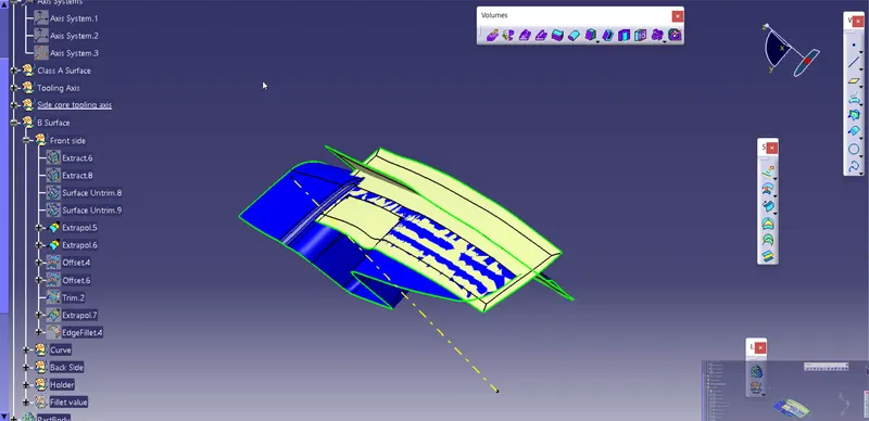
Fig: Extracted surfaces
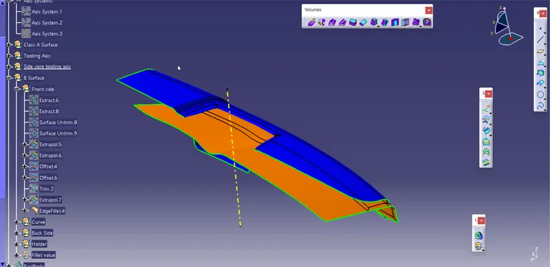
Fig: front part of the component
Following the same steps used for front part we create back part of the component.
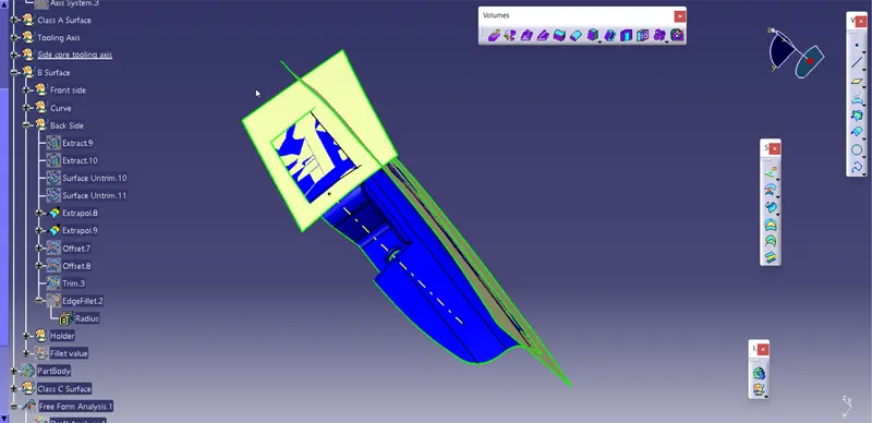
Fig: Extracted Surface
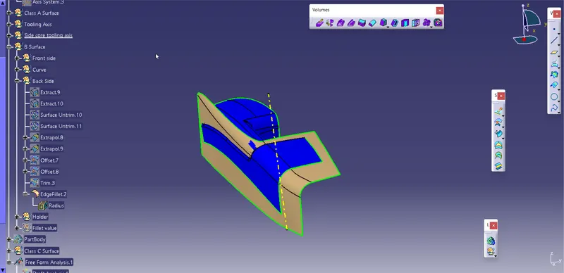
Fig: Back Part of the component
Now we have to create a filleted curve present on the side wall of the component.
- we create a profile for the sweep as shown in the figure.
- by using multiple extract and smooth curve we create a guide curve for the profile.
- by usnig sweep comand we crate a surface for the curve and offset it.
- now we used blend option to connect the two surface created.
- using join command we create it into a single surface.
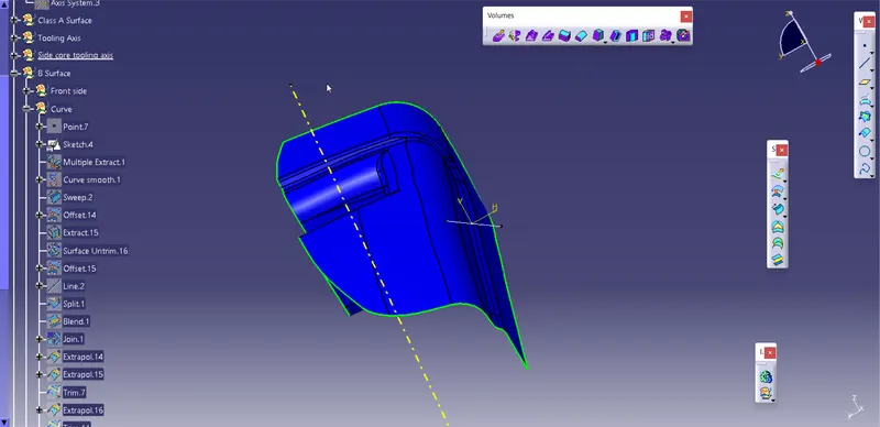
Fig: Profile
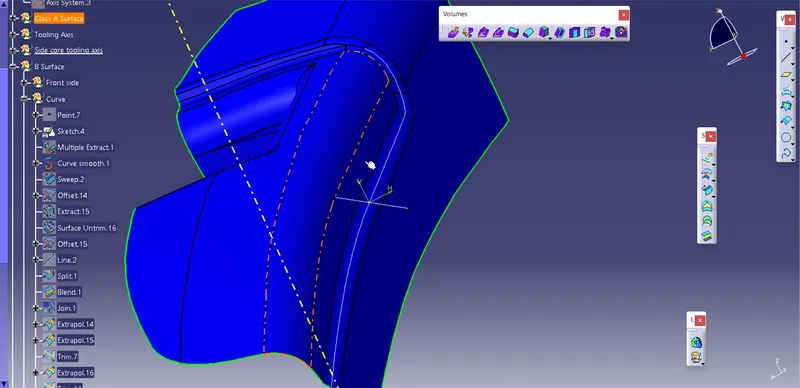
Fig; Guide Curve
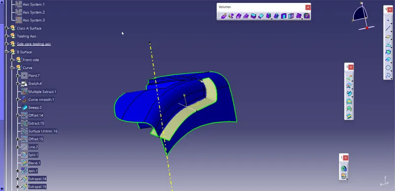
Fig: Swept Surface
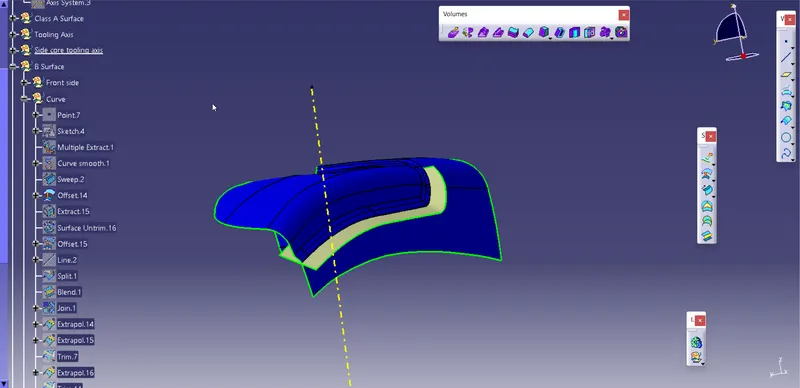
Fig: Offset Surface
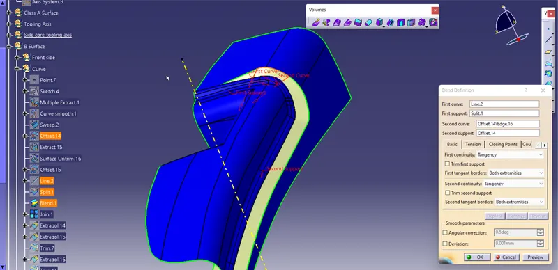
Fig: Blended Surface
To create pocket we follow similar steps as we did for front and back side of the component the we trim and fillet the edges to aquire the required shape.
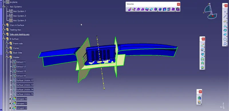
Fig: pocket surface
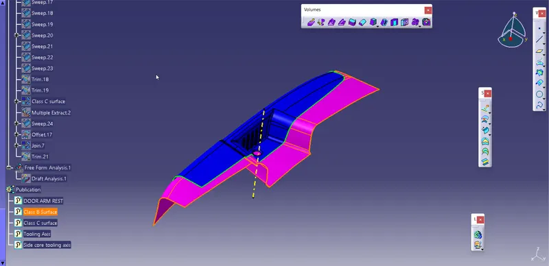
Fig: Creation of Class B Surface
Creating Class C Surface
For creating class C surface we have used two different methods after extracting the outer boundary of the component:
- Swept "with draft direction"
- Swept "with reference surface"
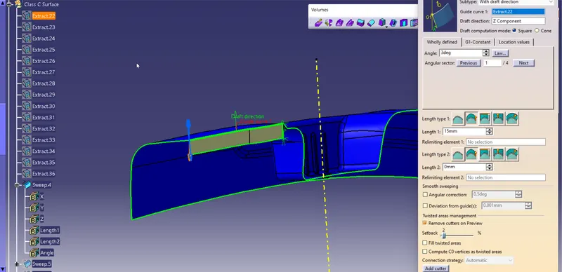
Fig: With draft direction
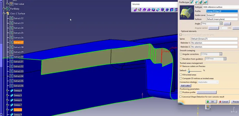
Fig: With Reference surface
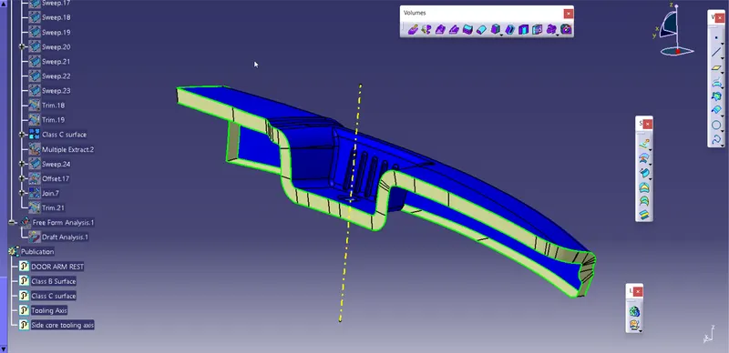
Fig: Class C Surface
Combining both Class A and Class C surface together.
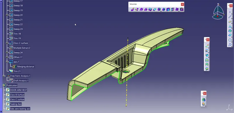
Fig: Combined Class A and Class C
Triming combined surface with class B to obtain surface component
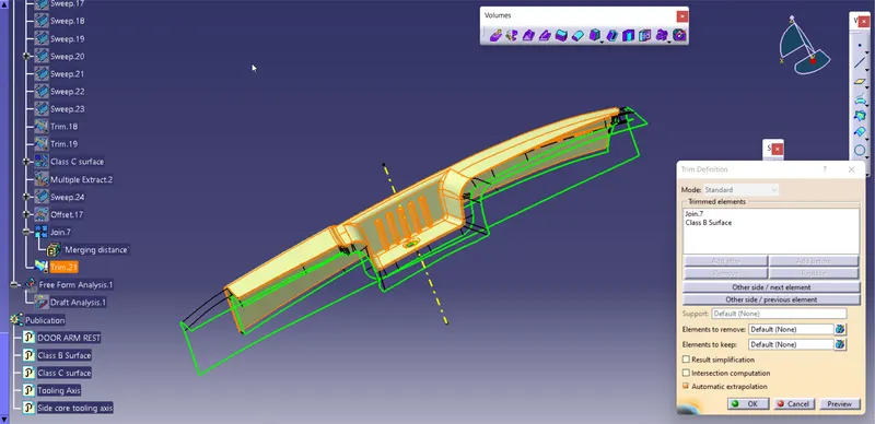
Fig: Surface Component
Converting suface component to solid component by using closed surface option.
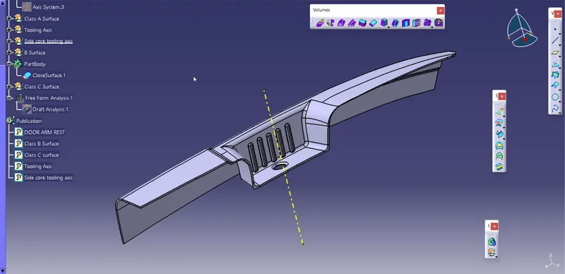
Fig: Solid Component
Draft Analysis
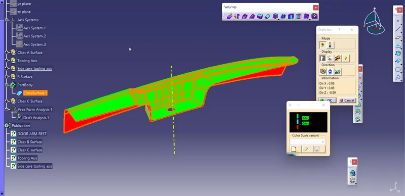
Fig: Draft analysis
Trees and views
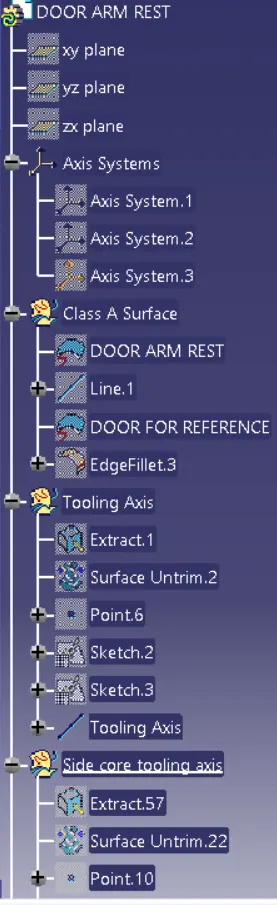
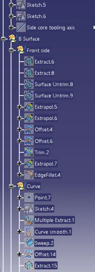
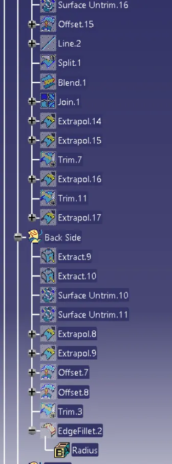
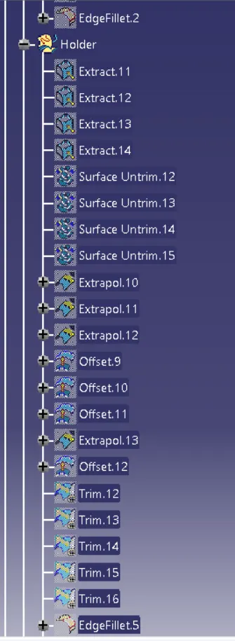
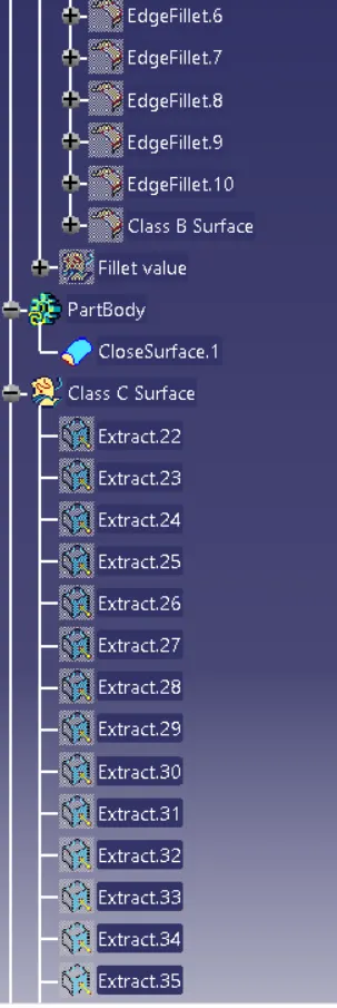
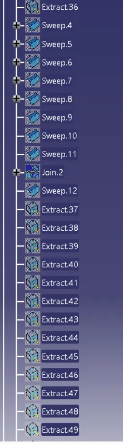
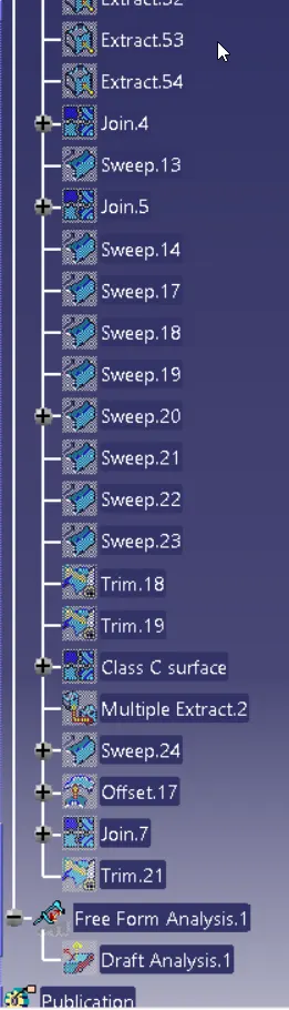
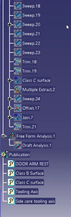
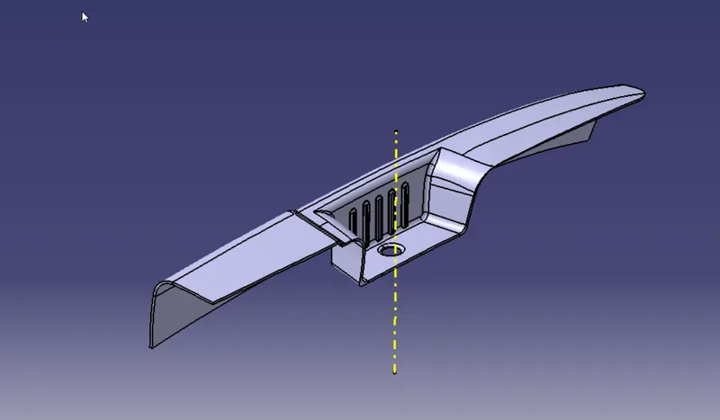
Fig: Isometric View
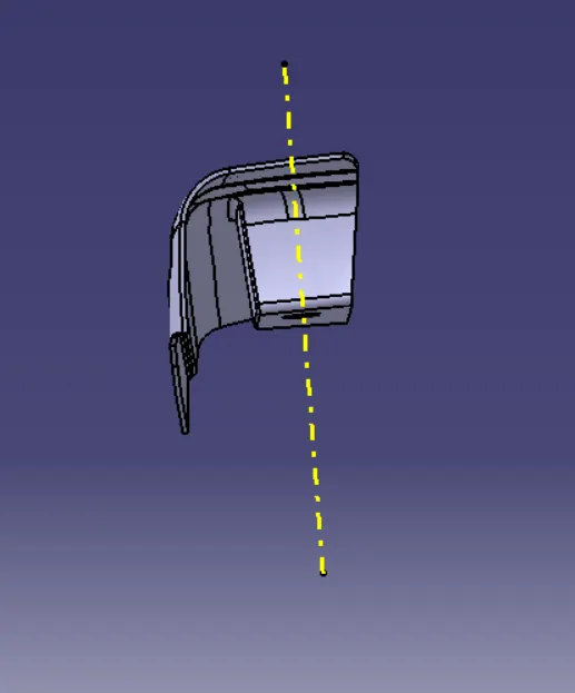
Fig: Front view
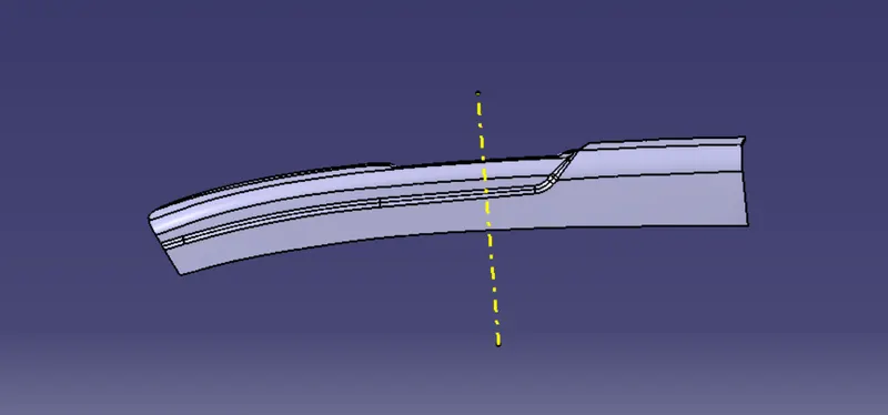
Fig: Side View
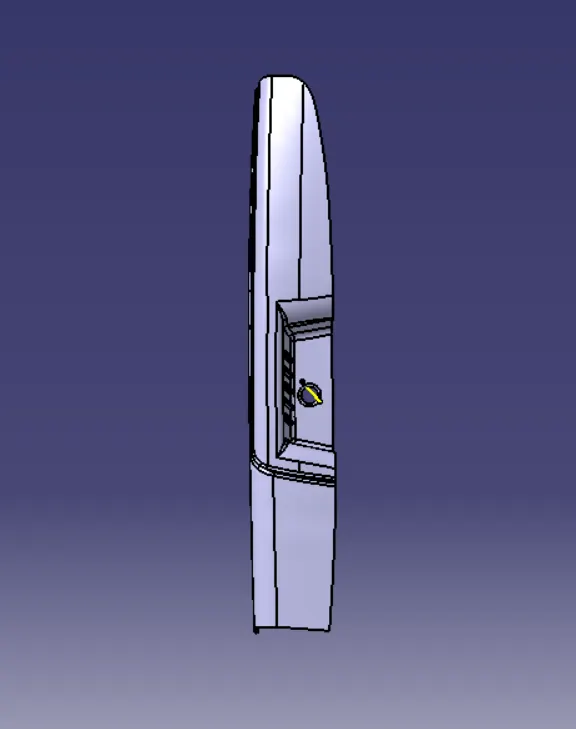
Fig: Top view