Week 8 - Challenge 3 - Switch Bezel Design
SWITCH BEZEL
In this we create switch bezel component using given Class A surface.
For the creation of component at first we need to provide tooling axis by examining the class a surface. To this component we create 2 dummy tooling axis in YZ and ZX axis after that bisecting both we create actual tooling axis.
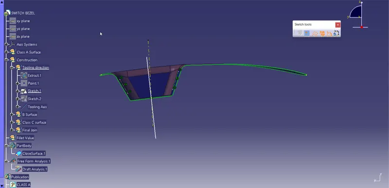
Fig: Dummy tooling axis 1
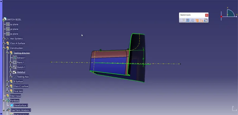
Fig: Dummy Tooling axis 2
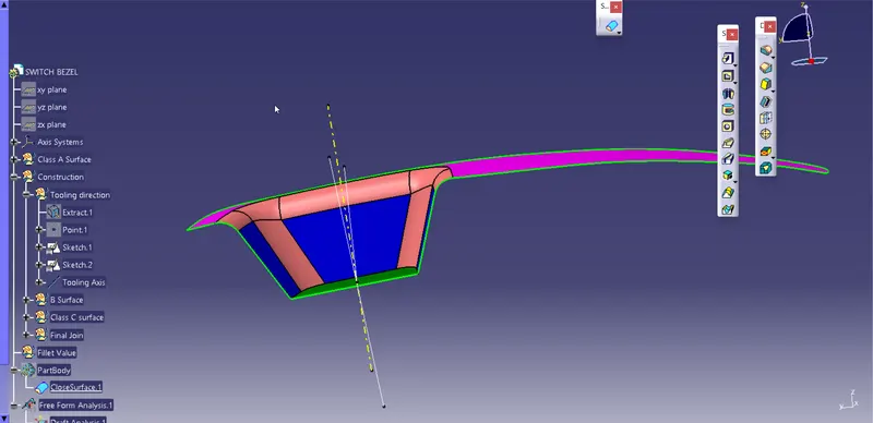
Fig: Actual Tooling Axis
Creating Class B Surface
At first we have created " Bezel Rest Surface" After extracting the required surface we offset it by 3mm.
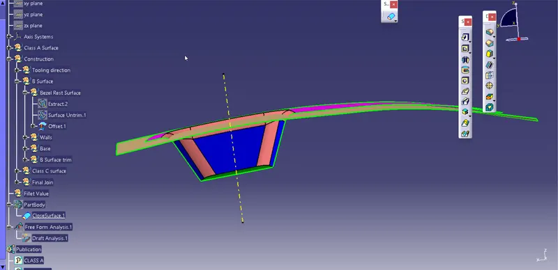
Fig: Bezel Rest Surface
Next we created "walls" in the same procedure at first we extract and extrapole the surface and then offset it by 3mm.
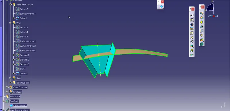
Fig: Walls
In the same process we create base.
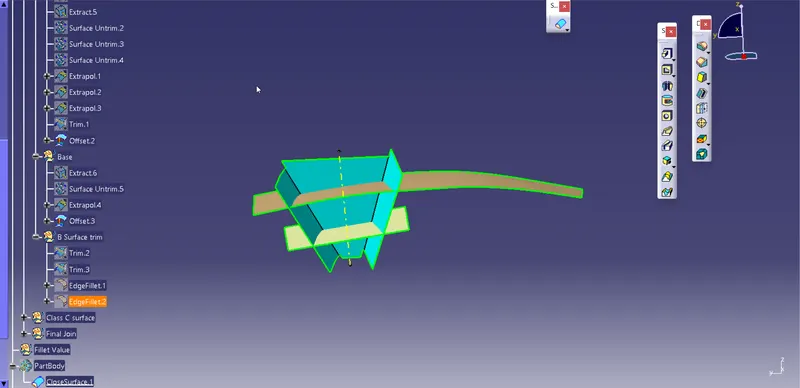
Fig: Base
Now we trim surfaces with respect to each other to aquire desired shape and provide fillets similar to Class A surface to get finshed Class B surface.
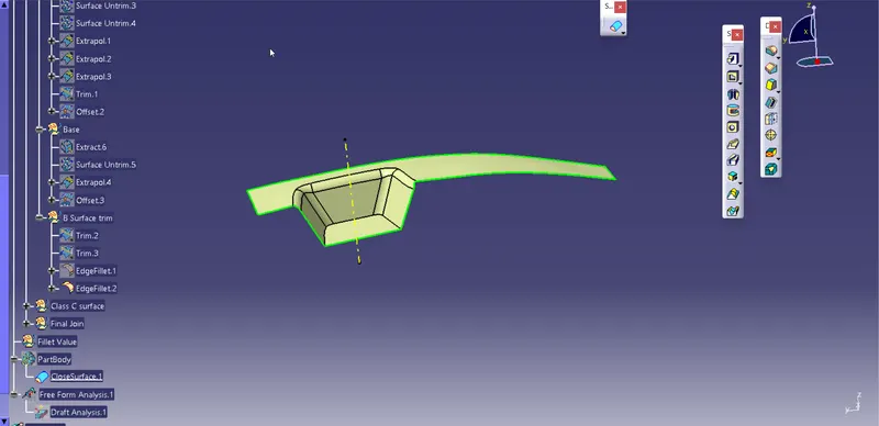
Fig: Finished Class B Surface
Next we create Class C surface
By using Class A surface we generate boundary by using multi extract option and then using sweep to sweep the boudary downwards with draft angle 3 degree.
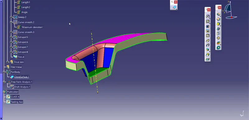
Fig: Class C Surface
Now we join both Class A and Class C surface together and then trim it with class B surface.
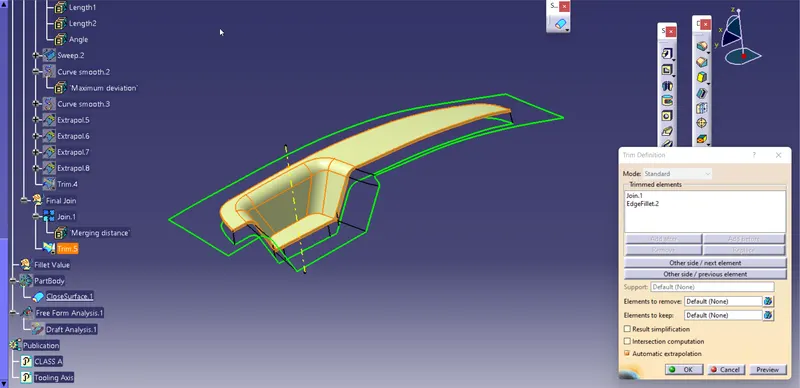
Fig: Surface Component
Now by using closed surface option we convert surface component to closed component.
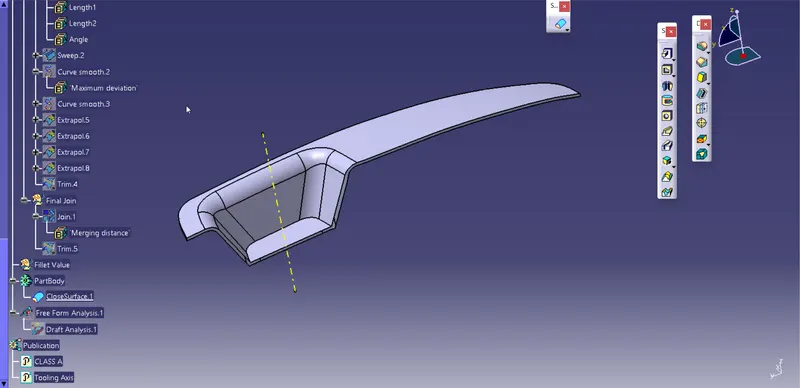
Fig: Switch Bezel
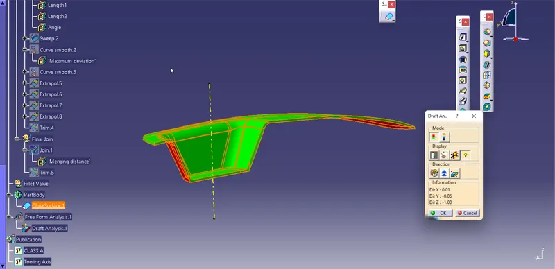
Fig: Draft Analysis
Trees And Views
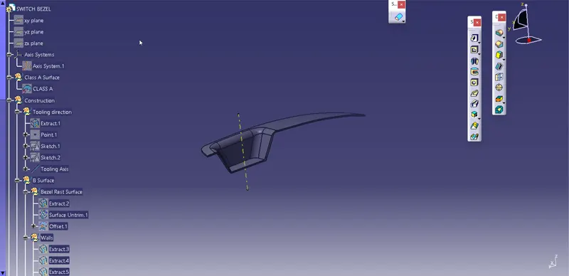
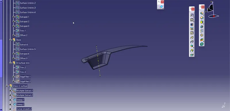
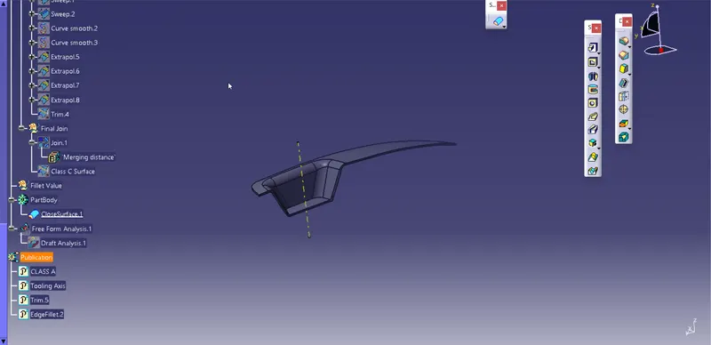
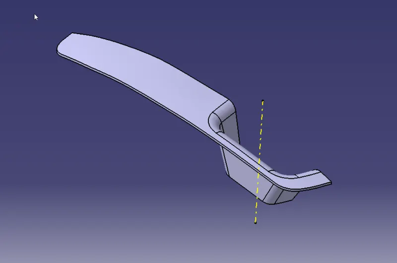
Fig: Isometric View
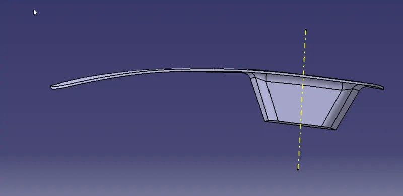
Fig: Front View
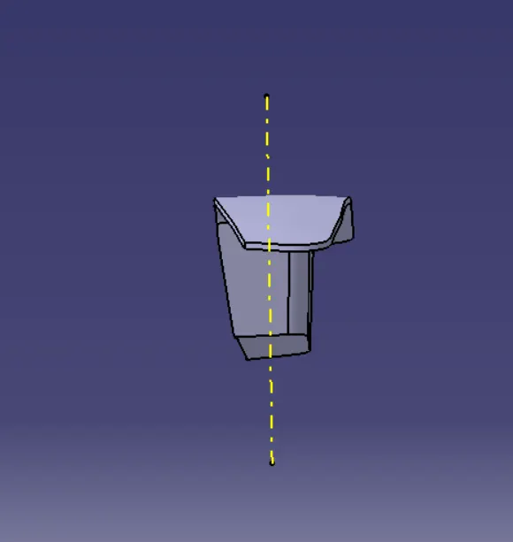
Fig: Side View
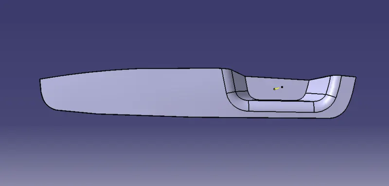
Fig: Top view