Week 8 - Challenge 2 - Base Bracket Design
We have been provided with class A surface of Base Bracket 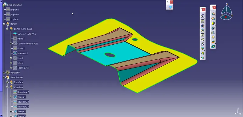
Fig: Class A Surface
As a first step we need to create tooling axis for the given Class A surface for that we need to create dummy tooling axis.
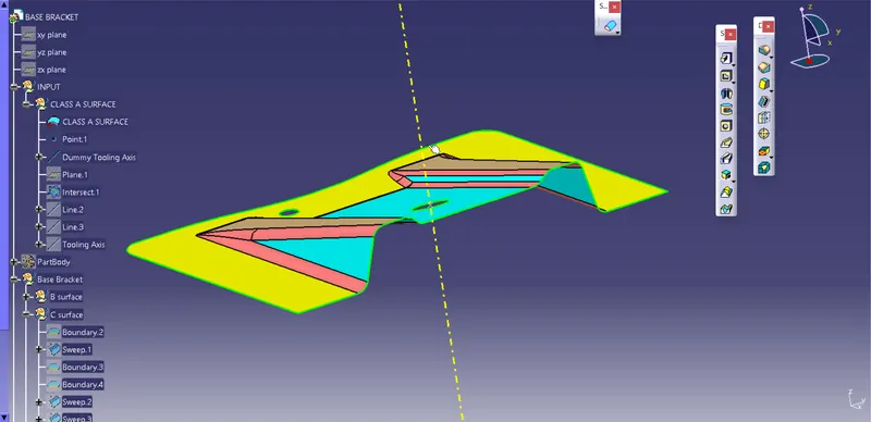
Fig: Dummy Tooling Axis
After Creating dummy tooling axis we create a intersecting profile using intersect after that we create lines on two parallel surfaces by using this we create bisecting line which is a actual tooling axis of the surface.
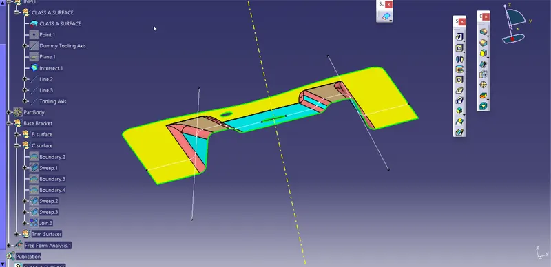
Fig: Tooling Axis
Draft Analysis on class A surface
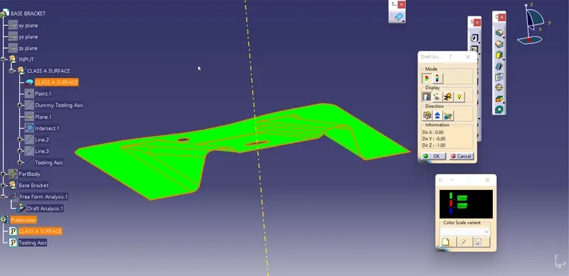
Fig: Draft Analysis
To create a Class B surface for a component we start it to design with ribs at first we extracted the required sides of the rib and after that unitrim and extropolate the surfaces.
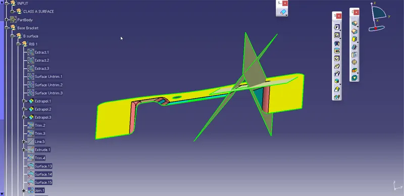
Fig: Extrapolated Surface
Now we trim the extrapolated surface as per the required shape and then offset it by 2.5mm to create class B surface.
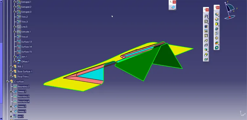
Fig: Class B surface Rib
Same procedure to be continued for 2nd rib also.
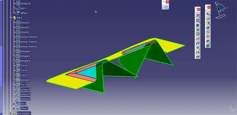
Fig: Ribs of Class B surface
By following the same procedure and commands used for ribs we create required base surfaces of the component.
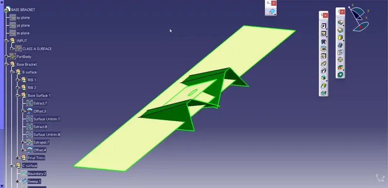
Fig: Base Surfaces before final trims
Final trims has to be performed to achieve the class B surface which is similar to the Class A Surface at distance of 2.5 mm and provide respective fillets to the edges i.e; 3+2.5 = 5.5mm.
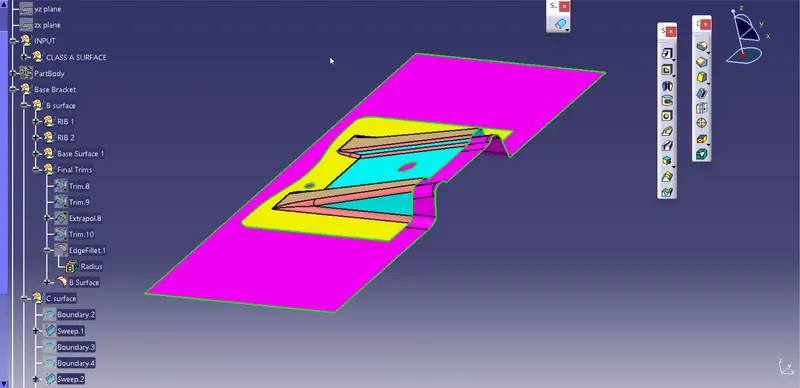
Fig: Class B surface
Now, we create Class C surface by using the boundary of class A surface and sweep it using "with draft direction" command by giving a draft angle of 3degrees.
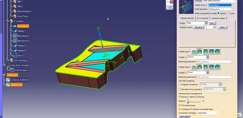
Fig: Class C surface
To create the component we need to trim class C surface with class B surface and get the required surface.
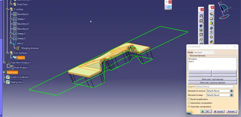
Fig: Surface Component
By using solid surface option we can convert surface component to solid component.
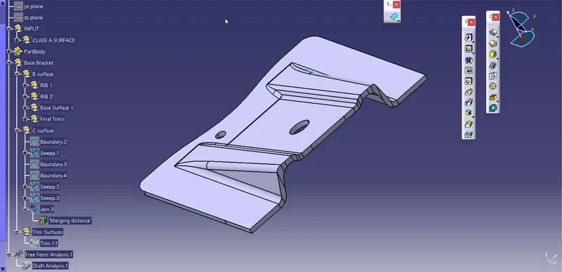
Fig: Solid Component
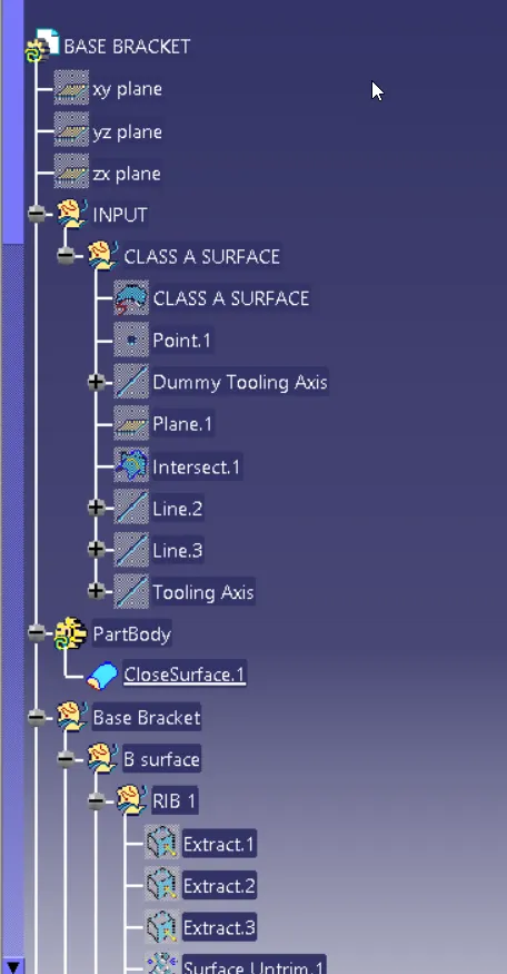
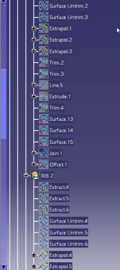
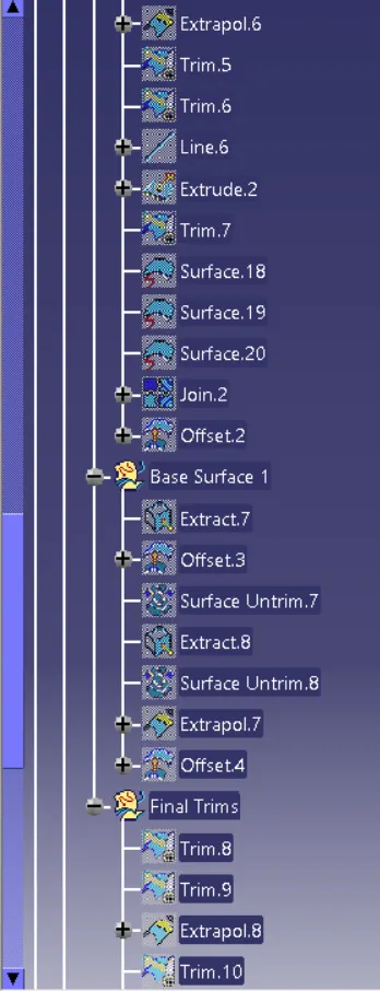
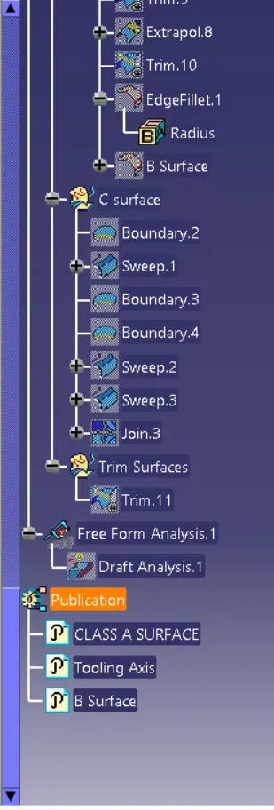
Tree Structure