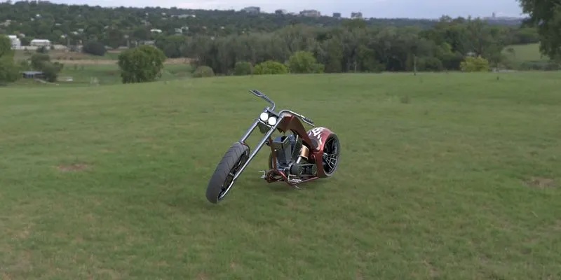
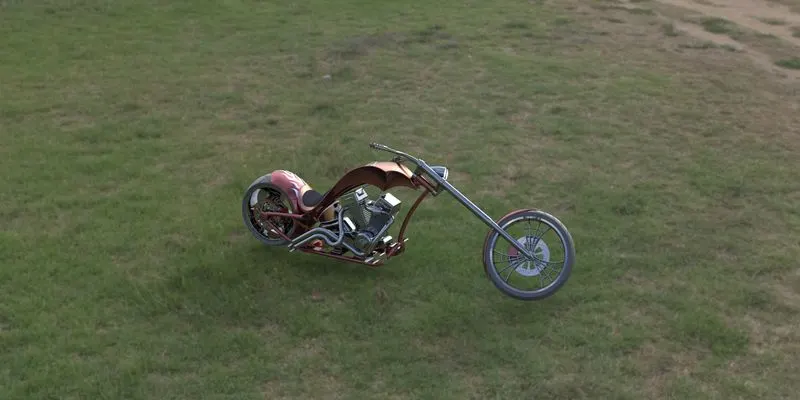
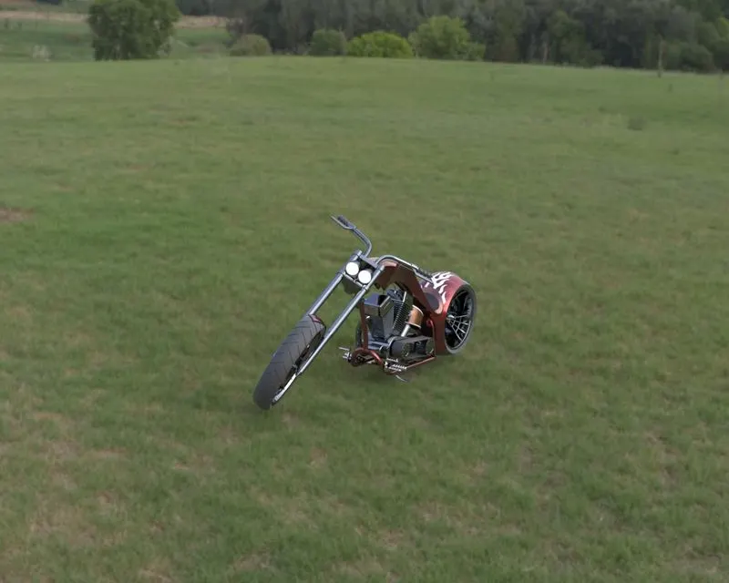
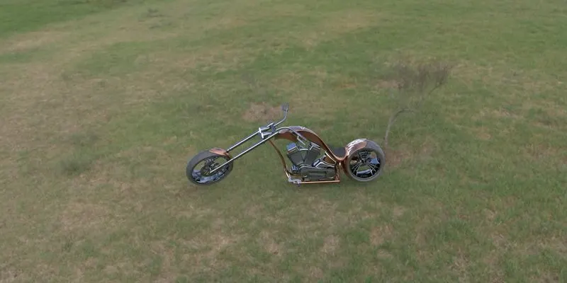
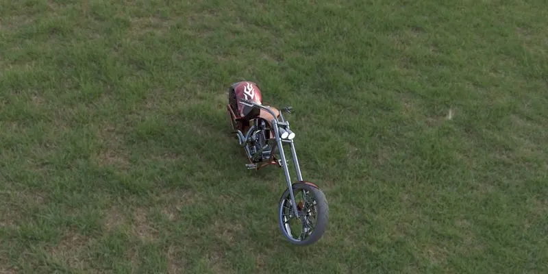
Photo Realistic Rendering
MODELING OF AMERICAN CHOPPER IN SOLIDWORKS
INTRODUCTION:
In this project we learn about the design and assembly of American chopper using SolidWorks. First we learn the basic commands and then we design the individual parts. After the design of every component we assemble the chopper. Then we add decals, lights and camera and we do rendering using SolidWorks visualization.
The components which we learn in SolidWorks are as follows:
- Transmission belt
- Chain
- Kickstand and foot pedal
- Front and rear tire with rim and sprocket
- Front fork
- oil tank and fuel tank
- Engine
- Chassis
- front and rear Fenders
OBJECTIVE:
- Learning basic commands of SolidWorks
- Using sketches we design all parts of the chopper
- Assembling all the parts in SolidWorks
- Learning the concept of decals and camera positions
- Rendering the American chopper by using SolidWorks visualization
The features used in the design of American chopper are:
- revolve boss
- extrude cut
- Mirror
- Shell
- linear pattern
- Fillet
- Extrude boss
- Chamfer
- projected curve
- Mate
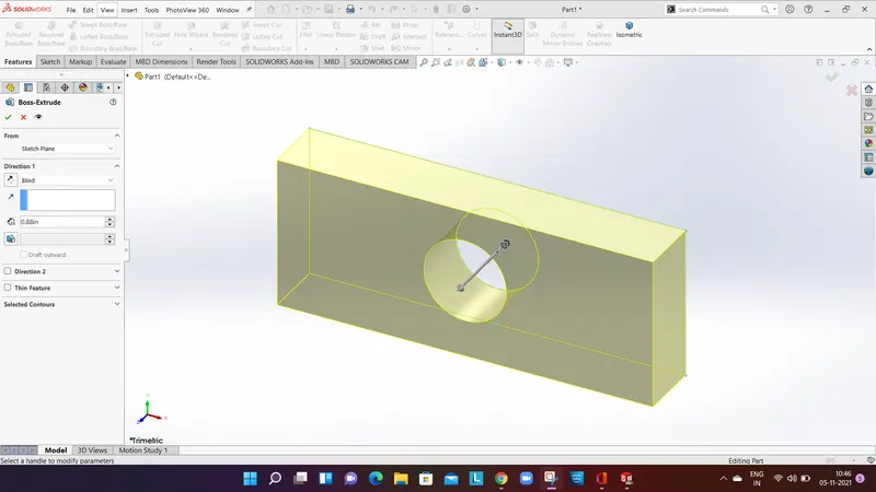
EXTRUDE BOSS:
Extrude boss is a feature that converts 2D sketch into a solid body. The boss extrude is located on the property manager window, According to our need we can give dimensions in required direction.
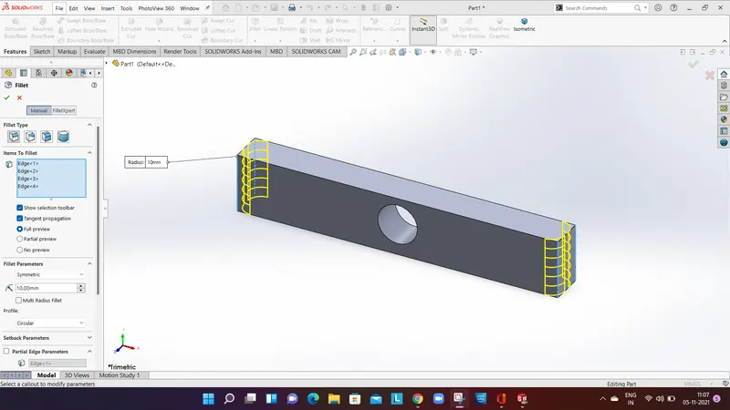
FILLET:
Fillets are used to remove the sharp edges and make it into a smooth edge. The material can be added or removed according to the condition of internal and external edges. Different types of fillets are used according to different types of parts.
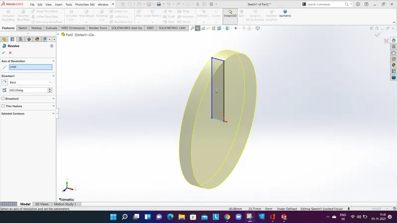
REVOLVE BOSS:
Revolve boss Revolves around the axis, by selecting the sketch axis a round material is formed. If there is no axis we can select an edge of the sketch to create a revolve part.
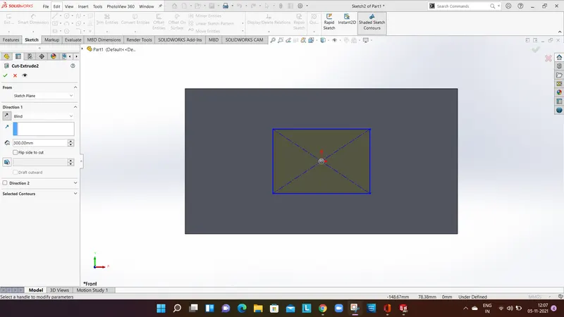
CUT EXTRUDE:
In a solid body if there are cuts to be made this feature comes in handy. cut extrude can give you a desired shape to the sketch or solid part, this basically remove material from the solid body.
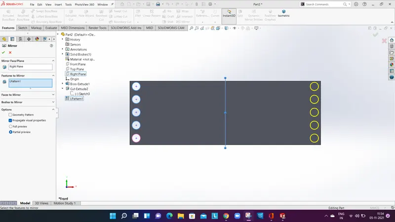
MIRROR:
The mirror feature creates a replica of a solid part. The mirror feature is used on an axis in order to mirror a solid part on the other side.
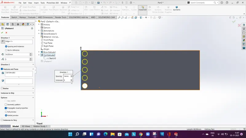
LINEAR PATTERN:
This feature is used to create single sketch to a multiple sketch. Multiple sketches can be created only in a linear path, specified sketches can be uniformly spaced to form a desired look.
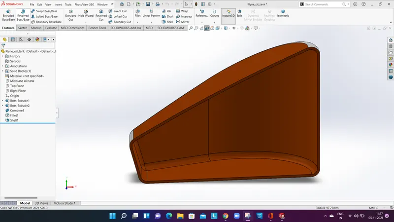
SHELL:
To know the geometry inside a body, whether it is hollow or not. By this tool we can find the thickness, geometry of the given part.
REFERENCE GEOMETRY:
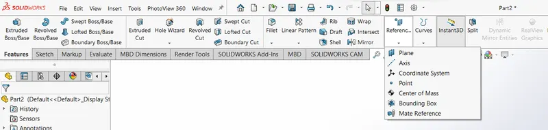
Reference geometry is a shape or form of a surface or or a solid. the features include are planes, axis, Coordinate and points.
MATE:
Mate creates geometric relationship between assembly and component. While adding mates the allowable direction of linear or rotational motion of component within its degree of freedom, visualizing the assembly's behavior.
The types of mates are:
- Coincident mate
- Tangent mate
- Concentric mate
- Angular mate
Part by part features and application of American chopper:
TRANSMISSION BELT:
Transmission belt transmits power with the help of pulleys. It is a solid body with the appearance of Matte rubber.
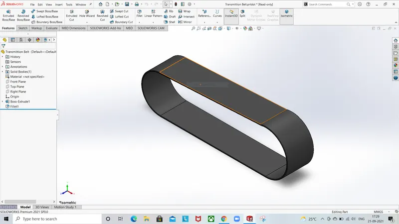
Features used to create transmission belt are:
- Sketch
- Extrude
- Offset
- Fillet
- Appearances
CHAIN:
The sketch of the chain are drawn using arcs and lines the line must be tangent to the arc. Then we sketch blocks and pins and extrude it. The blocks and pins are pattern along the path ,then the blocks are mirrored to the midplane And thus forming the structure of a chain. Then we give an appearance of metal Chrome to the chain.
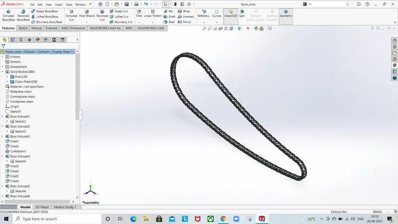
Feature used to create the chain are:
- Sketch
- Circle
- 3-point arc
- Block
- fillet
- Curve pattern
- Mirror
- Appearances
PEDAL:
A pedal is a rigid body used to rest the foot while riding the bike. Here we use extrude boss to make the specified design. then we use a Chrome metal appearance to the pedal.
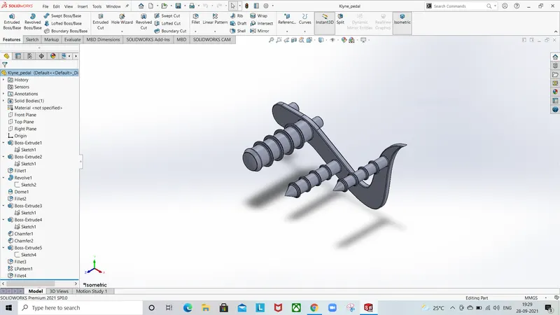
Features used to create the pedal are:
- Sketch
- Lines
- Circles
- Boss extrude
- Fillet
- revolve
- Champer
- Dome
KICKSTAND:
For kickstand we use sketch based on reference plane. We have used domes on top and bottom of the kickstand, we also use extrude cut option for the assembly purpose. The appearance used for the kickstand is metallic Chrome.
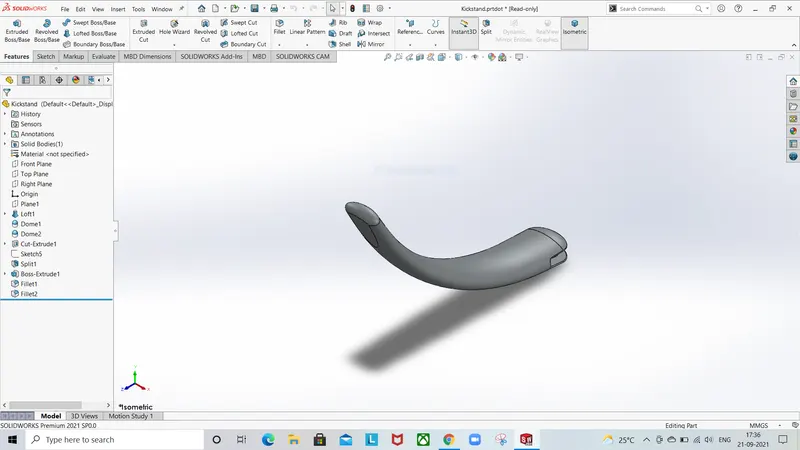
Features used to create the Kickstand are:
- Sketch
- Ellipse
- Spines
- Loft
- extrude cut
- Boss extrude
- Split
FRONT FENDER:
Front Fender is sketched using an axis and we create half curved part of solid body, Sharp edges are designed using the split tool to remove the material. The sharp edges of the front Fender are filleted. The appearance given to the front Fender is Siena.
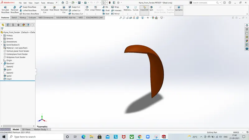
Feature used to create the front Fender are:
- Sketch
- Offset
- Revolve
- Spine
- Fillet
- Trim
REAR FENDER:
The procedure of rear Fender is same as the front Fender the difference between them is the size. The appearance for the rear Fender Is of metal paint named as Siena.
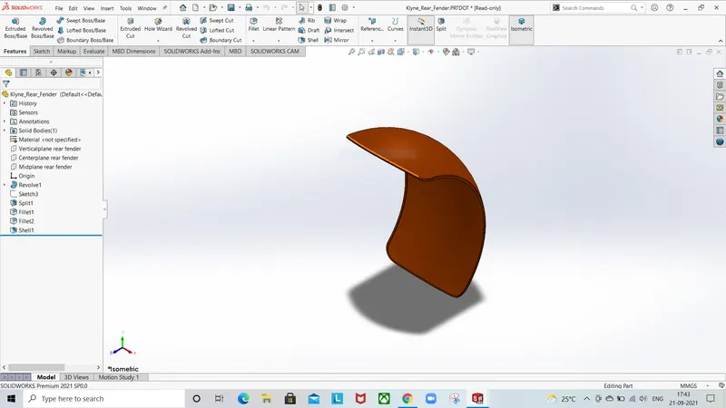
Feature used to create rear Fender are:
- Sketch
- Revolve
- Spine
- Fillet
- Shell
- Trim
- Extend
FRONT WHEEL:
To create front wheel first the rim was created by revolve boss Feature and then spider web pattern were created by using spines and offsets. Then the rotor and caliper where modelled. The tire is modelled with threads and appearances is given to tire of Matte rubber and the rotor is given an appearance of Chrome metal and caliper is given of Siena color.
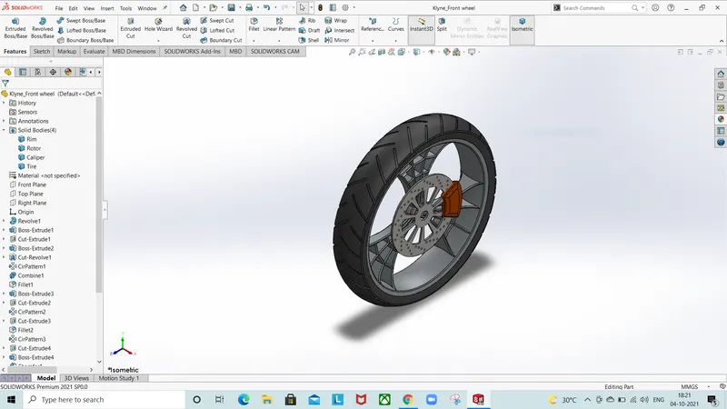
Feature used to create the front wheel:
- Sketch
- Lines
- Spine
- Revolve
- Extend
- Trim
- circular pattern
- Offset
- revolve cut
- Champer
- Fillet
REAR WHEEEL:
Rear wheel is used to accelerate the vehicle to move forward ,it is wider than the front wheel. the steps followed are the same as the front wheel and their appearance is same. Here only the sprocket is added to link the chain.
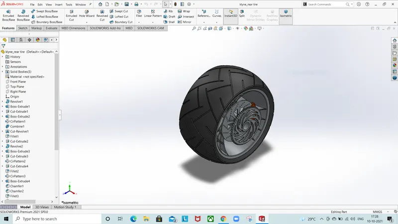
Feature used to create rear wheel:
- Sketch
- Lines
- 3-point arc
- Revolve
- Spine
- Extend
- Trim
- Offset
- extrude cut
- circular pattern
- Chamfer
- Fillet
FRONT FORK:
Front fork is attached to the front wheel and the chassis. It includes parts like handlebars, headlights, break, clutch and levers. First the half portion of the front fork is created and then it is mirrored with the plane. The cables are made using projected curves and grips are made for the handles of the front fork.
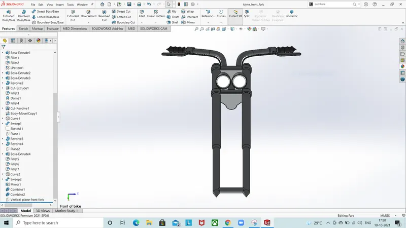
Features used to create front fork are:
- Sketch
- Lines
- Revolve
- Circle
- linear pattern
- Spine
- extrude cut
- Sweep
- Curve
- Plane
- Fillet
- Mirror
- Dome
CHASSIS:
Chassis Is the main frame of the chopper that holds components like Front fork, pedals, oil tank, engine, gas tank, kickstand and rear wheel. It uses features Such as extruded boss, spines, and revolving parts making mirror and sweep. The sharp edges are removed using the fillet option. The appearance given to the chassis is Siena color.
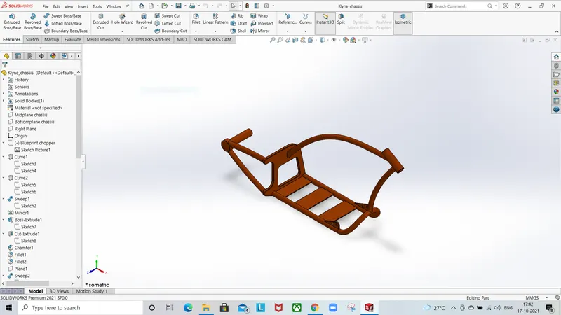
Features used to create the chassis:
- Blueprint sketch
- Curves
- Mirrors
- spines
- boss extrude
- Cut extrude
- Dome
- Revolve
- Split
- Champer
- Combine
ENGINE:
The main part of the American chopper is the engine. It provides necessary power to drive the bike, we have taken a reference picture to design the engine. The engine consists of parts like crankshaft, transmission belts and motors. We drew spines for the exhaust and also used projected curve and sweep option. The appearance given to the engine is of Chrome metal.
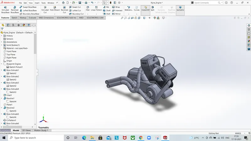
Feature used to create the engine are:
- Blueprint sketch
- Lines
- Circles
- Revolve
- circular pattern
- linear pattern
- cut extrude
- Boss extrude
- Mirror
- Curve
- composite curve
- Split
GAS TANK:
The gas tank is made up of spine and sweep feature. First the half part is made and then it is mirrored to the plane. Then we use a knit feature to create an individual part. Then we add fillets to the edges of the gas tank. At last we use shell option to check whether the gas tank is hollow or not.
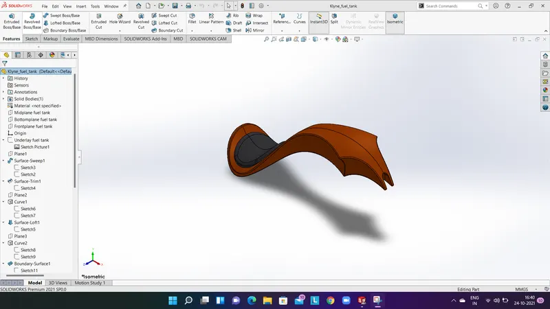
Feature used to create gas tank:
- Blueprint sketch
- Spine
- surface sweep
- surface trim
- surface boundary
- surface loft
- curve
- Mirror
- surface extrude
- Fillet
- Knit
- Cut extrude
- Shell
OIL TANK:
The oil tank is sketched using the top plane and extruded about a distance to make it as a structure of oil tank and then the other sketches are added on the midplane and it is extruded and then combined together at the end. To remove sharp edges fillet is added. The shell function is added to check whether it is hollow. The appearance of the oil tank is Siena color.
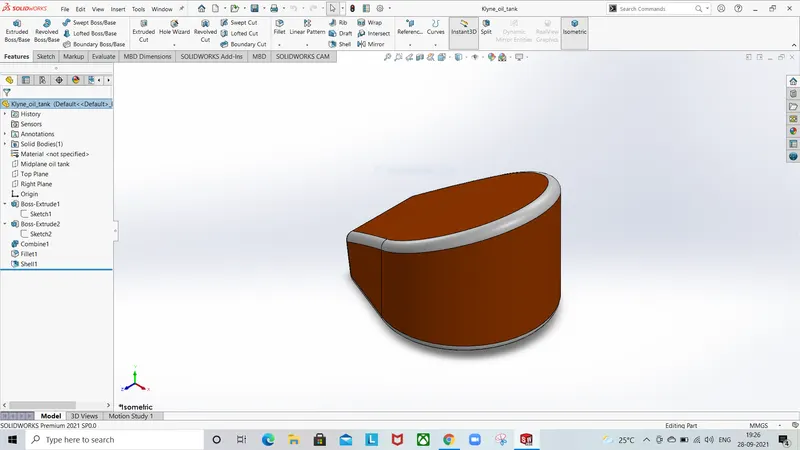
Feature used to create oil tank:
- Lines
- Boss extrude
- 3-point arc
- Fillet
- combine
- Shell
ASSEMBLY:
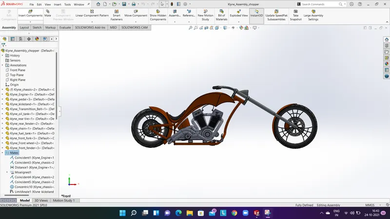
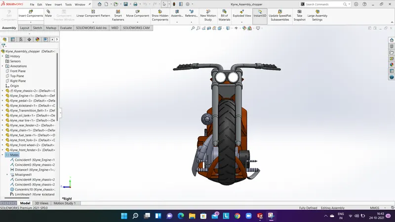
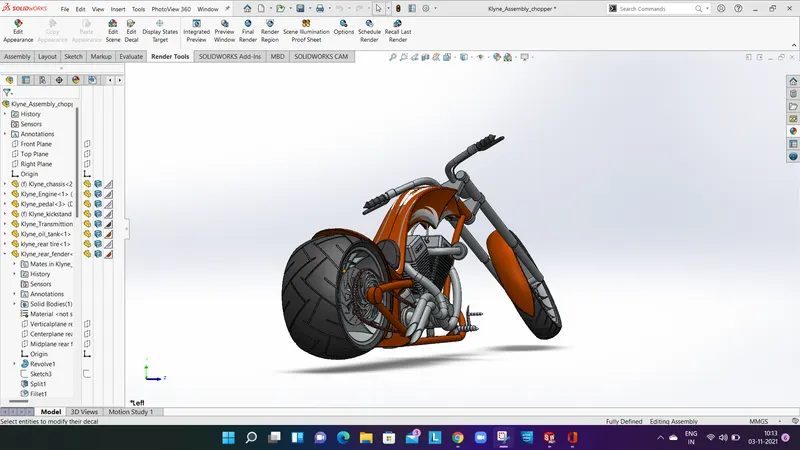
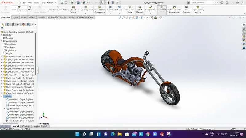
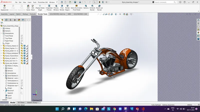
In assembly all the parts of the American chopper are assembled in this process. The first component we take is chassis. To the chassis we fix pedals, kickstand and the engine then we fit the transmission belt and then comes the chain we mate all the component using mate option. After that the front fork and the fuel tank is mated Then the front and rear tires and fenders are fixed .Thus forming the complete assembly of the American chopper.
DECALS:
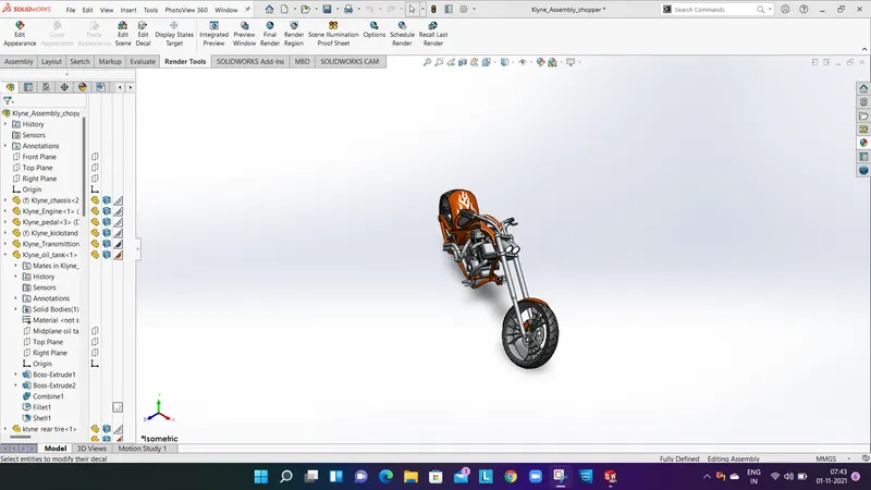
Decal is something that consists of a picture, image, pattern, or a design that is printed on a metal body. We have added decals on gas tank, oil tank and rear Fender to give a nice appearance.
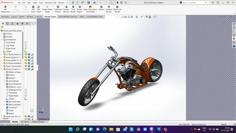
RENDERING:
Rendering is a particular view of realistic image. By doing rendering we can get to know how the component will look in the environment. For the American chopper the rendering is done through Solid works visualization. In this we deal with camera angles, changing the color of individual parts Etc. we can change the background images, brightness, Gamma value to make the component look realistic. There are two options to render ,the first one is fast reader and the second one is accurate rendering. In accurate rendering we can get better resolution and more detail visuals of the American chopper.