Photo Realistic Rendering
American chopper
Objective :
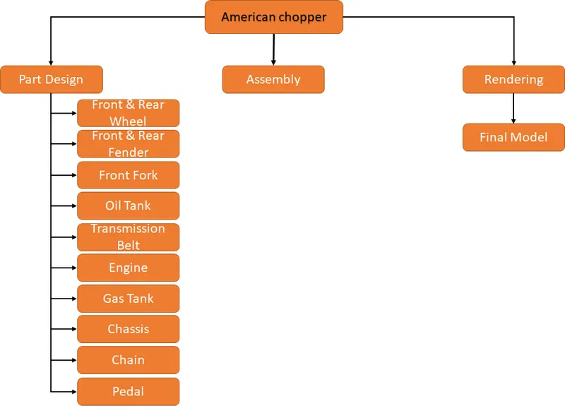
- The objective of the project is to model the different parts of the american chopper using solid works.
- To assembly the different parts of the chopper.
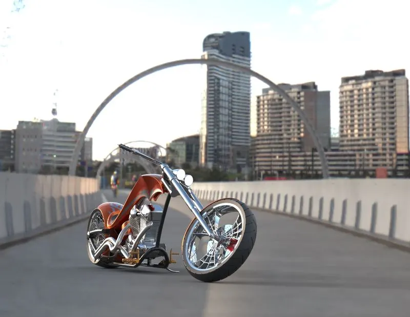
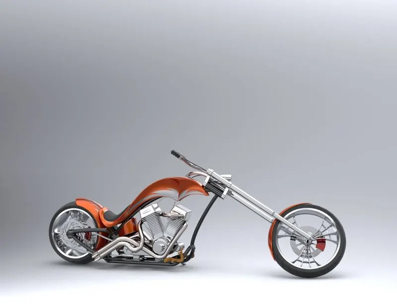
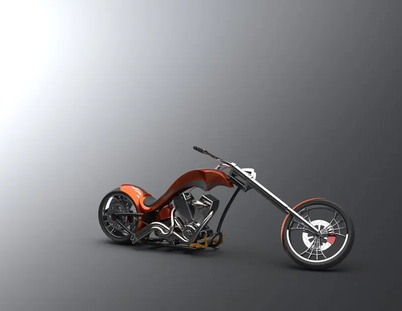
- To create the photorealistic rendering for the assembled chopper using solidworks photoview 360 and solidworks visualize.
Introduction :
American chopper built by Orange Country Chopper (OCC) for a specific corporate or celebrity customer. Theme bikes are motorcycles in which the theme of the motorcycle takes priority over everything else, influencing the frame dimensions, paint scheme, and overall 'feel' of the motorcycle. The function of motorcycle usually takes a backseat to the presentation of the theme, and these motorcycles attract attention solely on the premise of the theme itself.
A chopper is a type of custom motorcycle which emerged in California in the late 1950s. A chopper employs radically modified steering angles and lengthened forks for a stretched-out appearance. They can be built from an original motorcycle which is modified ("chopped") or built from scratch. Some of the characteristic features of choppers are long front ends with extended forks often coupled with an increased rake angle, hardtail frames (frames without rear suspension), very tall "ape hanger" or very short "drag" handlebars, lengthened or stretched frames, and larger than stock front wheels.
The purpose of the project is to create a aesthetic CHOPPER using solidworks.
Design methodology :
Features Description :
sketch :
A sketch is almost always the first step in designing a new part. This feature in solidworks used to draw 2D geometry with reference to plane.
Boss Extrude :
Extrude is a feature that is used to convert the 2D sketch into the 3D model.
Fillet :
Fillet/Round creates a rounded internal or external face on the part. You can fillet all edges of a face, selected sets of faces, selected edges, or edge loops.
Offset :
Offset entities takes a copy of your existing geometry and copies it at an offset. Instead of recreating geometry, you can use this to quickly sketch based on model geometry. Offset entities is a great tool for enlarging or shrinking your sketch geometry.
Chamfer :
Machinists use chamfers to "ease" otherwise sharp edges, both for safety and to prevent damage to the edges. A "chamfer" may sometimes be regarded as a type of "bevel", and the terms are often used interchangeably.
Extrude cut :
Extrude cut is a feature which helps to remove material from the 3D model.It is just opposite to the Boss extrude feature.
Loft :
The loft feature is an important tool for modeling in SolidWorks. The loft feature creates a shape by making transitions between multiple profiles and guide curves. This tool is very valuable for modeling complex surfaces. You can do some really cool stuff when you use this feature properly.
shell :
The shell tool hollows out a part, leaves open the faces you select, and creates thin-walled features on the remaining faces. If you do not select any face on the model, you can shell a solid part, creating a closed, hollow model. You can also shell a model using multiple thicknesses.
revolve :
Create a sketch that contains one or more profiles and a centerline, line, or edge to use as the axis around which the feature revolves. Click one of the following revolve tools.
Dome :
Dome is a rounded vault forming the outside face or body or structure with a circular base.
Combine :
The common function allows you to add two bodies together, and keep the area that is common to them. To use this feature, we will select the common button, and then under Bodies to Combine, select the two bodies.
Circular Pattern :
circular patterns to create multiple instances of one or more features that you can space uniformly around an axis.
Linear Pattern :
linear patterns to create multiple instances of one or more features that you can space uniformly along one or two linear paths.
Dynamic Mirror :
Dynamic Mirror tool used to mirror the selected line,surface or face to the selected plane or line.
Projected curve :
The projected curve is used to project the selected sketched curve onto a face or sketch.
Composite curve :
The composite curve is used to combine the selected curve,edge and sketch into a single curve.
Trim :
The trim command is used to remove or erase the excess line, edges of intersecting line on a 2D sketch.
Parts to be modeled for chopper :
1. Transmission Belt :
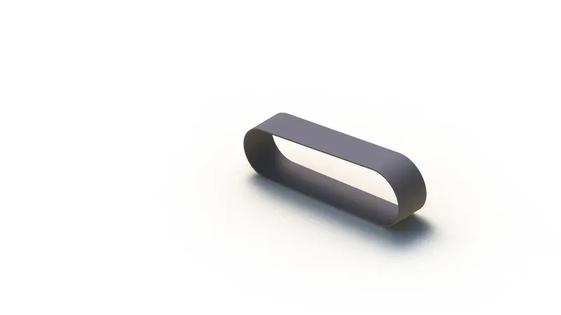
Transmission Belt is a loop of flexible material used to transmit power by the means of pulleys. Belts transmit power efficiently through the pulleys. they are the one of the cheapest means used power transmission. other advantages are noiseless working, shock absorption during working, no lubrication, minimal maintenance, high tolerance for misalignment.
Features used to create Transmission Belt
- Sketch
- Offset
- Extrude
- Fillet
- Appearances
Appearance -Matte Rubber
2. KickStand :
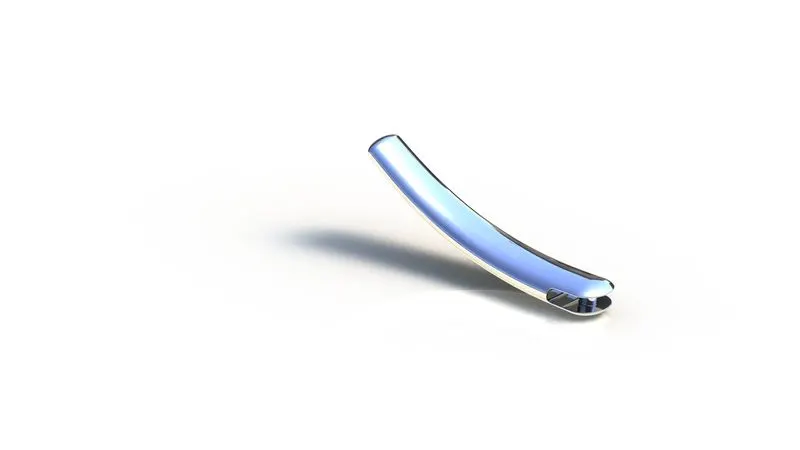
A kickstand is a device on a motorcycle that allows the bike to be kept upright without leaning against another object or the aid of a person. A kickstand is usually a piece of metal that flips down from the frame and makes contact with the ground. A side stand style kickstand is used in this model. It is a single leg that simply flips out to one side, usually the left side, and the bike then leans against it. Side stands can be mounted to the chain stays right behind the bottom bracket or to a chain and seat stay near the rear hub. Side stands mounted right behind the bottom bracket can be bolted on, either clamping the chain stays or to the bracket between them, or welded into place as an integral part of the frame.
Features used to create KickStand
- Sketch
- Loft
- Dome
- Extrude Boss
- Extrude cut
- Fillet
- Split
- Appearances
Appearance -chrome plate
3. Front Fender :
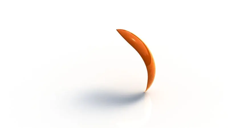
Fenders are also called as mudguards. These mudguards are fixed over the front tire of the bike. It protects bike rider from water and mud caused to thrown up by the bike. A front fender will help protect your feet and ankles from spray if you're riding in the rain or even through a puddle.
Features used to create Front Fender
- Sketch
- Offset Entities
- Trim entities
- Revolve
- Dynamic mirror
- Split
- Appearances
Appearance -sienna paint
4. Rear Fender :
Fender are what will keep you from having a skunk stripe on your backside if you ride in the rain, and a front fender will help protect your feet and ankles from spray if you're riding in the rain or even through a puddle.
Features used to create Rear Fender
- Sketch
- Offset Entities
- Trim entities
- Revolve
- Appearances
Appearance -sienna paint
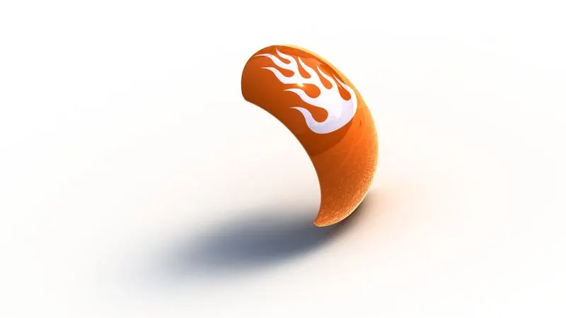
5. Oil Tank :
An oil tank is a safe container for flammable fluids. Though any storage tank for fuel may be so-called, the term is typically applied to part of an engine system in which the fuel is stored and propelled (fuel pump) or released (pressurized gas) into an engine. Fuel tanks range in size and complexity from the small plastic tank of a butane lighter to the multi-chambered cryogenic space shuttle eternal tank.
Features used to create Oil Tank
- Sketch
- Boss Extrude
- Combine
- Fillet
- Shell
- Appearances
Appearance -sienna paint
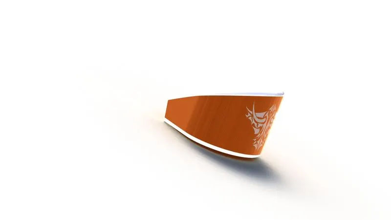
6. Chain :
A bicycle chain is a roller chain that transfers power from the pedals to the drive-wheel of a bicycle, thus propelling it. Most bicycle chains are made from plain carbon or alloy steel, but some are nickel-plated to prevent rust, or simply for aesthetics. Bicycle chains are made of multiple pairs of steel outer plates and inner plates held together by rivets. A roller separates each pair of inner plates. The rivet (pin) is pressed tightly through both outer plates. The rivet then pivots freely on the inner plates and roller.
Features used to create Chain
- Sketch
- Trim
- Fillet
- Blocks
- Extrude
- Patterns
- Appearances
Appearance -polished copper
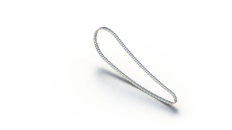
7. Pedal :
The gear shift lever is located on the lower left side of the motorcycle. By sliding your left foot under the gear shift lever and lifting it upward, you shift to a higher gear. Each click equals one gear. You can always find first gear by tapping the gear shift lever down until it won't go any further. Most manual transmission two-wheelers use a sequential gearbox with five or six gears to shift into using a foot lever.
Features used to create Pedal
- Sketch
- Extrude
- Fillet
- Linear pattern
- Dome
- Chamfer
- Appearances
Appearance -chrome plate
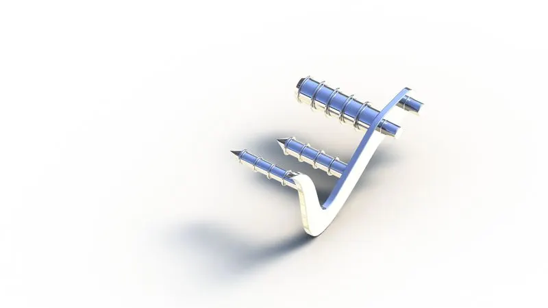
8. Front Wheel :
It is a wheel designed for bike to support the front body of bike. In this spider webbed spokes are used. These spokes are connecting rods between rim and hub.The main work of spokes is to transfer the loads between rim and hub which causes due to weight of rider. The increasing wheel size will decrease the diving force from wheels which results in decrease in acceleration of wheels. It consists of rotor and calliper which is used to stop the vehicle.
Features used to create Front Wheel
- Sketch
- Revolve
- Trim
- Fillet Entities
- Boss/Base Extrude
- Revolve Cut
- Linear pattern
- Chamfer
- Fillet Features
- Cut Extrude
- Circular Pattern
- Appearances
Appearance --tyre-matt rubber, (rim, rotor, calliper)-chrome plate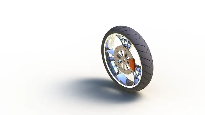
9. Rear Wheel :
A wheel may be a circular block of a tough and sturdy material at whose centre has been bored a circular hole through that is placed Associate in Nursing shaft bearing concerning that the wheel rotates once an instant is applied by gravity or torsion to the wheel concerning its axis, thereby creating along with one in all the six straightforward machines. once placed vertically below a supporting platform or case, the wheel turning on the horizontal shaft makes it doable to move significant loads; once placed horizontally, the wheel turning on its vertical shaft makes it doable to regulate the spinning motion accustomed form materials once mounted on a column connected to a rudder or a chassis mounted on different wheels, one will manage the direction of a vessel or vehicle once connected to a crank or engine, a wheel will store, release, or transmit energy.
Features used to create Rear Wheel
- Sketch
- Revolve
- Trim
- Fillet Entities
- Boss/Base Extrude
- Revolve Cut
- Linear pattern
- Chamfer
- Fillet Features
- Cut Extrude
- Circular Pattern
- Appearances
Appearance --tyre-matt rubber, (rim, rotor, calliper)-chrome plate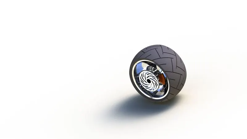
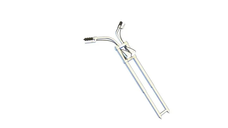
10. Front Fork :
A motorcycle fork connects a motorcycle's front wheel and axle to its frame, typically via a yoke, also known as a triple clamp, which consists of an upper yoke joined to a lower yoke via a steering stem, a shaft that runs through the steering head, creating the steering axis. Most forks incorporate the front suspension and front brake, and allow the front wheel to rotate about the steering axis so that the bike may be steered. Most handlebars attach to the top clamp in various ways,
while clip-on handlebars clamp to the fork tubes, either just above or just below the upper triple clamp. Most motorcycles today use telescopic forks for the front suspension. The forks can be most easily understood as simply large hydraulic shock absorbers with internal coil springs. They allow the front wheel to react to imperfections in the road while isolating the rest of the motorcycle from that motion.
Features used to create Front Fork
- Sketch
- Extrude
- Trim
- Revolve
- Split
- Plane
- Convert entities
- Move/copy Body
- Dome
- Mirror
- Combine
- Curve
- Sweep
- Appearance
Appearance – Chrome plate, arial light, matt rubber
11. Chassis :
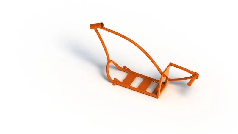
A chassis is the load-bearing framework of an artificial object, which structurally supports the object in its construction and function. Chassis is the main support structure of the vehicle which is also known as 'Frame'. It bears all the stresses on the vehicle in both static and dynamic conditions. In a vehicle, it is analogous to the skeleton in living organisms. A motorcycle's chassis or frame forms its skeleton. All the components of a motorcycle, like the suspension, wheels, fuel tank, seats, handlebars etc, are attached to this base structure which lends a motorcycle its strength and ability to handle well. Back bone frame, Single cradle frame, Double cradle frame, Perimeter frame, Trellis frame and Monocoque frame are the types of motorcycles frame by construction.
Features used to create Chassis
- Sketch
- Offset
- Convert entities
- Project Curve
- Trim
- Plane
- Sweep
- Split
- Revolve
- Cut Extrude
- Fillet
- Combine
- Appearance
Appearance -sienna paint
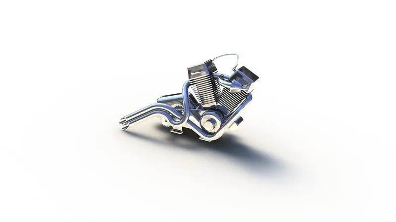
12. Engine :
An engine or motor is a machine designed to convert one form of energy into mechanical energy. Heat engines, like the internal combustion engine, burn a fuel to create heat which is then used to do work. A motorcycle engine is an engine that powers a motorcycle. Motorcycle engines are typically two-stroke or four-stroke internal combustion engines. Most engines have a gearbox with up to six ratios. The rider changes gears on motorcycles using a foot-pedal and manual clutch, but early models had hand-levers. More recently, some have automatic or semi-automatic gearboxes.
Features used to create Engine
- Sketch
- Convert entities
- Trim
- Revolve
- Boss extrude
- Cut extrude
- Offset
- Dome
- Fillet
- Project curve
- Composite curve
- Sweep
- Mirror
- Circular Pattern
- Split
Appearance – Chrome plate
13. Gas Tank :
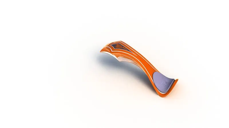
A fuel tank (also called a petrol tank or gas tank) is a safe container for flammable fluids. Though any storage tank for fuel may be so called, the term is typically applied to part of an engine system in which the fuel is stored and propelled (fuel pump) or released (pressurized gas) into an engine. The fuel tank is a reservoir that holds the fuel supply and helps maintain its temperature at a level below its flash point. The fuel tank also serves as an important means of dissipating heat from the fuel that is returned from the engine.
Features used to create Gas Tank
- Sketch
- Trim
- Project cuve
- Convert entities
- Sweep Surface
- Loft Surface
- Fill surface
- Surface trim
- Surface knit
- Sweep cut
- Fillet
- Appearances
Appearance -sienna paint
Assembly :
Combining multiple parts that fit together to create assemblies is called ASSEMBLY in SOLIDWORKS. We integrate the parts in an assembly using Mates, such as Concentric and Coincident. Mates define the allowable direction of movement of the components.
Feature used for assembly
- Insert component
- Mates
- Mirror
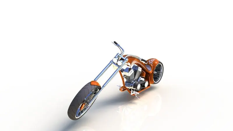
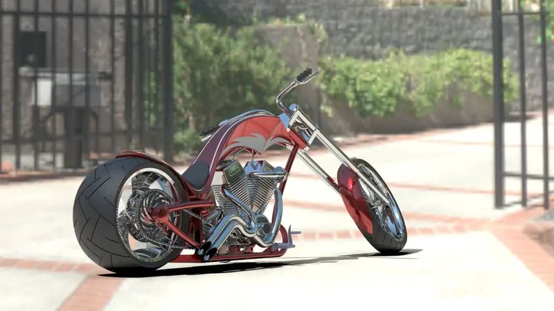
Rendering :
Rendering is the process of creating realistic images of the Photorealistic model with the environment.Rendering has been done in two ways in solidworks. The following are the two ways,
- Photoview 360
- Solidworks Visualize
In the photorealistic model some of the mate conditions and positions are changed to render realistic models.
Then the photorealistic model is rendered into realistic images with different views.
Conclusion :
- The different parts of the chopper are modeled.
- The parts are assembled.
- The realistic image was rendered with the use of the Photoview 360 & Solidworks visualize.