Photo Realistic Rendering
MODELING OF AMERICAN CHOPPER USING SOLIDWORKS
Objectives:
To model and create individual parts of the chopper using Solidworks. Then to assemble the different parts into a chopper and to add decals to make it look more realistic. To render photorealistic images of the finished chopper.
Introduction:
The report contains the details of part modelling, assembly and final rendering of an American Chopper using SOLIDWORKS. The workflow as well as the various tools and features used in this project is described here.
Design Methodology:
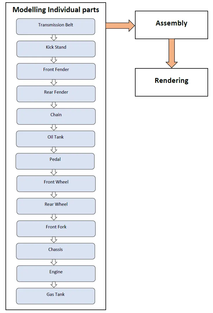
The flowchart shows the workflow in this project,
SOLIDWORKS features used:
Sketch - The sketch is the basis for a 3D model, it can be created in any of the default planes (Front Plane, Top Plane and Right Plane), on a created plane or on a face.
Different tools in sketch,
- Line
- Spline
- Circle
- Rectangle
- Arc
- Fillet
- Offset
- Trim and extend entity
- Convert entity
- Mirror
- Linear sketch pattern
- Smart dimension
Extruded bose/base - This feature converts a 2D sketch element into a 3D solid feature.
Extruded cut - This is a handy feature to aid in material removal of a 3D model using 2D sketches.
Revolved boss/base - This feature tool is used to create a solid 3D model around an axis. The sketch is revolved around an axis to add materials to it.
Revolved cut - This tool allows to cut a profile around an axis creating complex geometry in a single feature.
Swept boss/base - This feature helps to sweep a closed profile along a path sketch to construct a 3D model. This feature requires a minimum of two sketches.
Swept cut - Swept cut allows to cut a model by sweeping a closed profile sketch along a path sketch. This feature requires a minimum of two sketches.
Fillet - Creates a rounded internal or external face along one or more edges on a solid or surface feature.
Chamfer - Creates a bevel feature along an edge, chain of tangent edges or a vertex
Patterns - Patterns are used to create multple instances of one or more features that are spaced uniformly , along a specified path, line or along an axis, line along a 3D curve.
Shell - This feature is used to hollow out a part. The faces that are selected are left open and on the remaining faces thin-walled features are created. If a face is not created shell creates a closed hollow model.
Dome - This feature adds one or more domes to selected planar or non planar faces.
Split - Split is used to create multiple bodies or surfaces from a single part or surface. This feature can create as well as consume the cut bodies
Combine - There are 3 different options available in this feature
- Add: To merge multiple bodies together into one.
- Subtract: To remove multiple bodies from main body.
- Common: To add two bodies together and keep the area that is common to both.
Some of the features used in Surface Modelling are described below,
Swept Surface - The surface is created by sweep profile and sweep path.
Lofted Surface - These surfaces are generated by multiple 3D curves or existing edges.
Boundary Surface - This creates surfaces that can be tangent or curvature continous in both directions.
Filled Surface - This feature creates a surface to fill the gap in a model.
Surface Trim - This feature is used to cut away material from a surface.
Extended Surface - Extends one or more edges or faces on a surface, based on end conditions and extension type.
Surface Knit - Combines two or more adjacent, non-intersecting surfaces into a single surface body. The surfaces must join at edge and if the resulting knit surface encloses a volume, then a solid body can be created from it.
Description of the Chopper parts and the various features used in it
1. Transmission Belt
Transmission belt is used to transmit power from the engine to the input shaft of the gearbox.
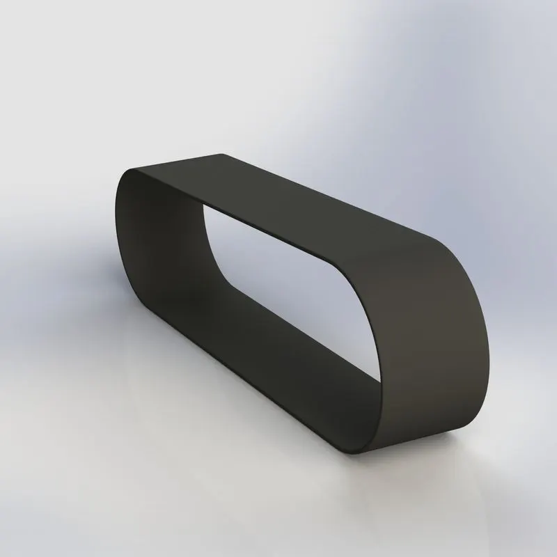
Features used to create transmission belt:
- Sketch
- Extruded Boss
- Fillet
2. Kickstand
Also known as sidestand, is a single leg supporting structure that flips out on one side (usually the left side) that allows the bike to lean against it.
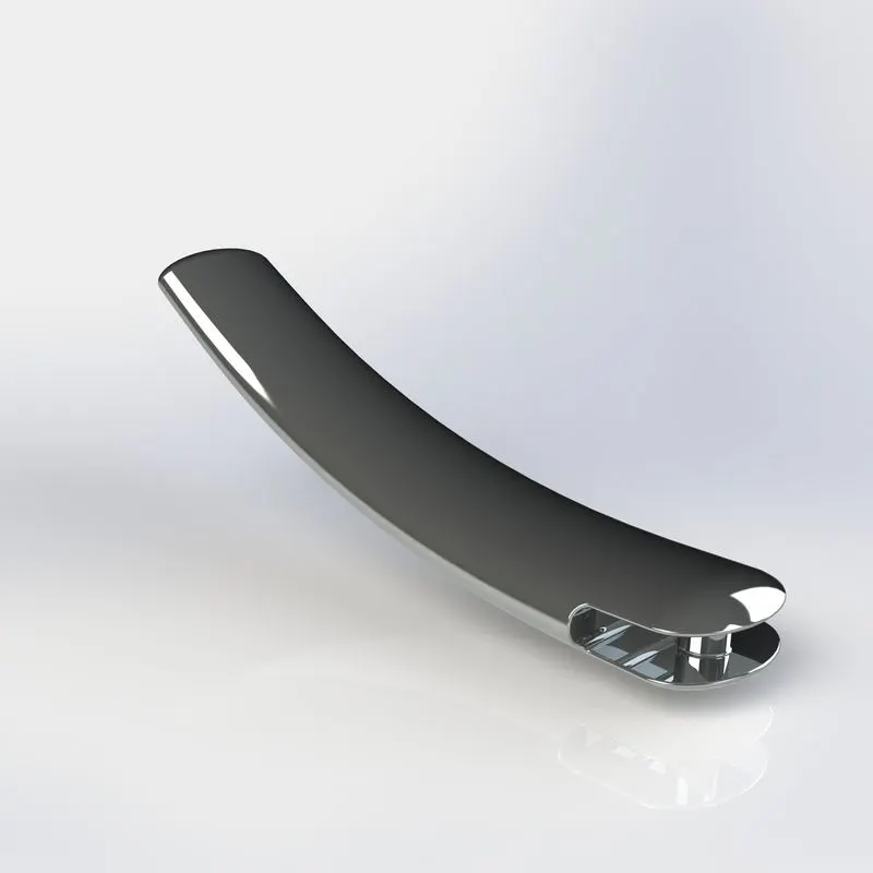
Features used to create kickstand:
- Sketch
- Loft
- Dome
- Extruded Cut
- Split
- Extruded Boss
- Filltet
3. Front Fender
In two wheelers front fender is a part mounted on the front fork just above the wheel. It is also known as a mud guard and it protects the rider as well as part of the engine and chassis from water, mud, rocks, etc while riding.
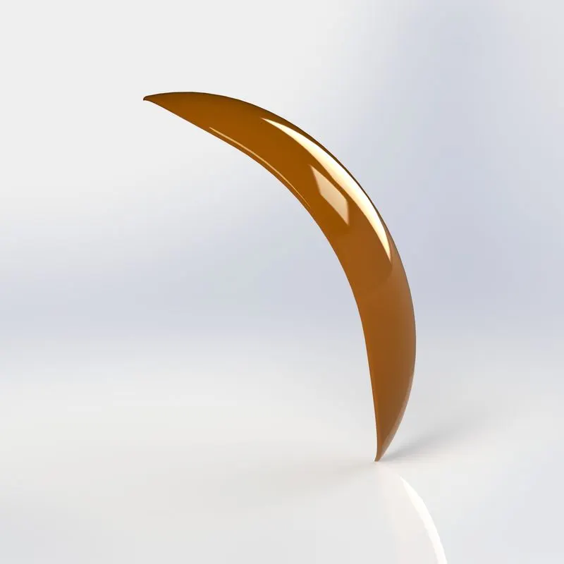
Features used to create front fender:
- Sketch
- Revolved Boss
- Split
- Fillet
4. Rear Fender
In a two wheeler this provides the same functions as a front fender. It is situated above the rear wheel and is mounted to the rear part of the chassis.
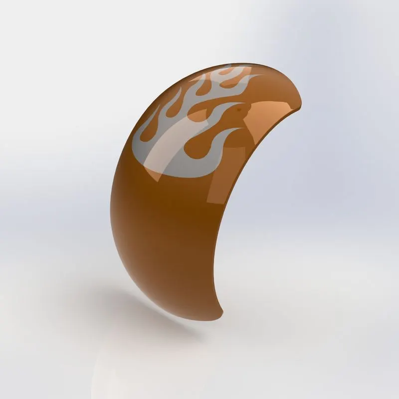
Features used to create rear fender:
- Sketch
- Revolved Boss
- Split
- Fillet
- Shell
5. Chain
Chain is part of the drivetrain. It transmits power from the gearbox to the rear wheel. It is made of a number of links linked together.
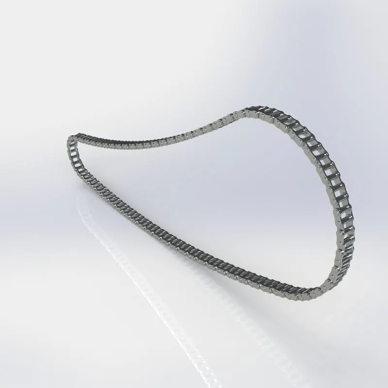
Features used to create Chain:
- Sketch
- Extruded Boss
- Fillet
- Curve driven Pattern
- Mirror
6. Oil Tank
The engine used in this chopper has a dry sump lubrication system. Hence the engine oil is stored outside the engine in this oil tank. It is hollow inside.
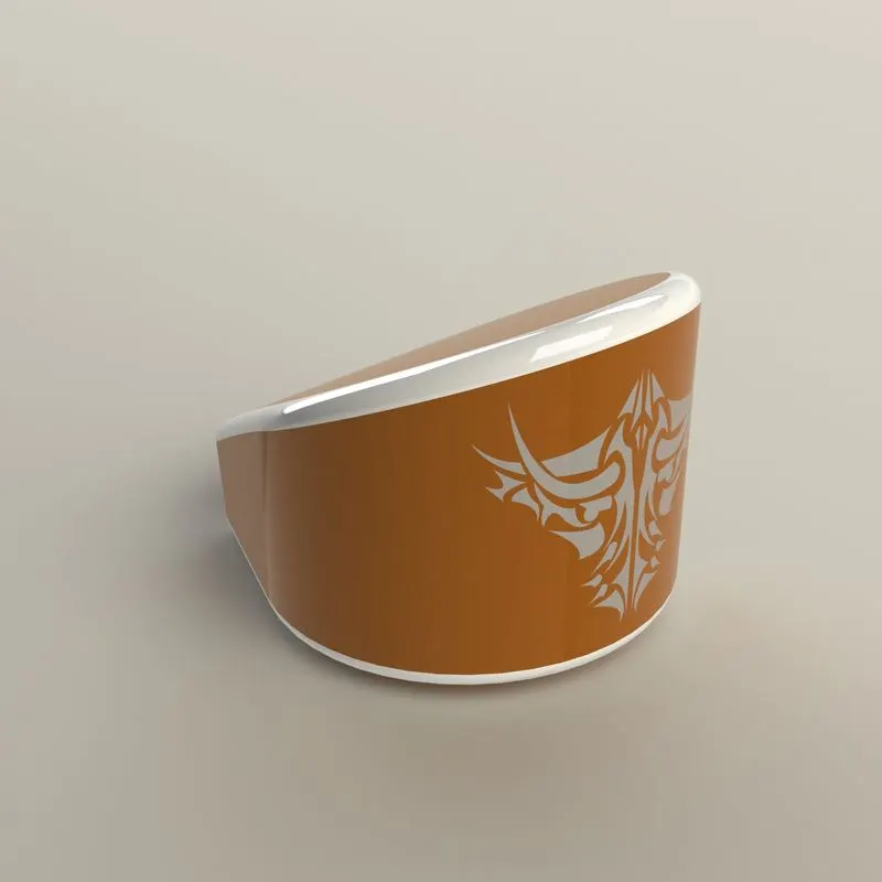
Features used to create Oil Tank:
- Sketch
- Extruded Boss
- Combine
- Fillet
- Shell
7. Pedal
Pedal is an external part that is attached to the sides of the chassis. It is used by the rider to rest his/her leg while riding.
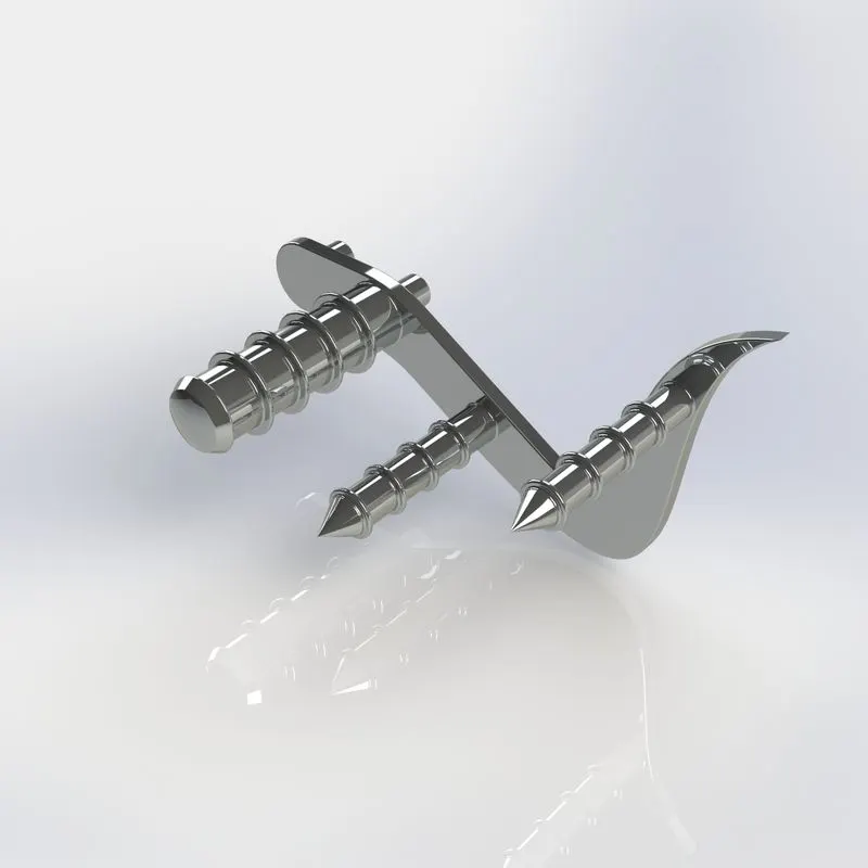
Features used to create pedal:
- Sketch
- Extruded Boss
- Fillet
- Revolved Boss
- Dome
- Chamfer
- Linear Pattern
8. Front Wheel
Front wheel is one of the important part of a vehicle that allows them to move, it consist of the rim and tyre. The tyre is made up of rubber material and provides grip with the road surface for the vehicle to move. The rim is made up of a metal alloy and it also contains the braking system made up of rotor and caliper.
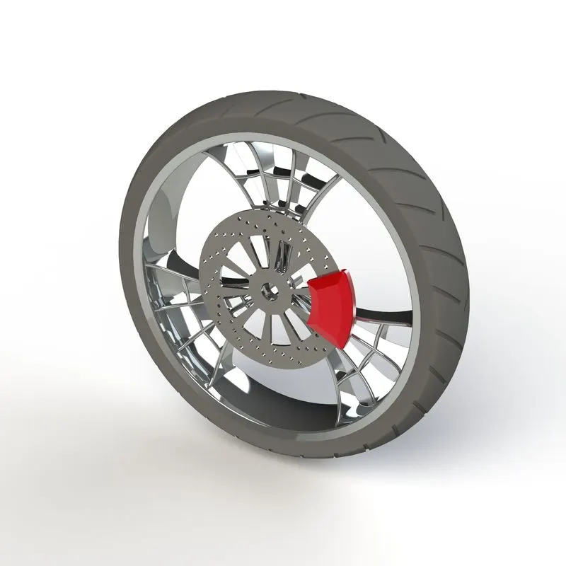
Features used to create front wheel:
- Sketch
- Revolve
- Extruded Boss
- Extruded Cut
- Revolved Cut
- Circular Pattern
- Combine
- Fillet
- Chamfer
- Revolved Boss
9. Rear Wheel
Rear wheel serves the same purpose as the front wheel, additionally it has a mount for the rear sproket for the chain drive. Power from the engine goes to the rear wheel, hence it is a lot wider than front wheel to provide more traction.
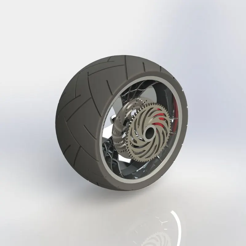
Features used to create Rear wheel:
- Sketch
- Revolved Boss
- Extruded Boss
- Extruded Cut
- Circular Pattern
- Combine
- Revolved Cut
- Fillet
- Chamfer
10. Front Fork
It also acts as the front shock absorber and it connects the front wheel to the chassis. The fork is mounted to the chassis in such a way that it is pivoted, this allows to turn the fork along with the handle enabling the vehicle to take turns. Here the headlights, handlle bar, brakes, axle is modelled into the fork.
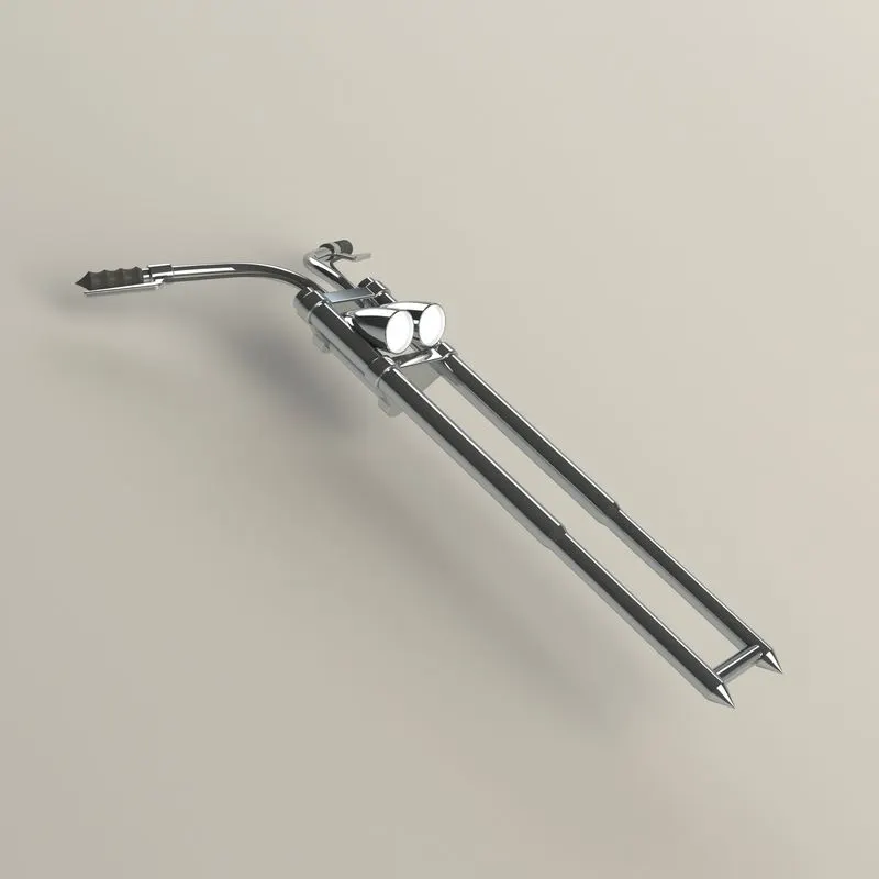
Features used to create Front Fork:
- Sketch
- Revolved Boss
- Extruded Boss
- Fillet
- Linear Pattern
- Extruded Cut
- Dome
- Revolved Cut
- Move/Copy
- Project Curve
- Swept Boss
- Mirror
- Combine
11. Chassis
The is also called as the frame. It is made up of hollow tubes, usually welded together. All the components such as the engine, pedals, gas tank, front fork, rear tyre, oil tank are mounted to the chassis.
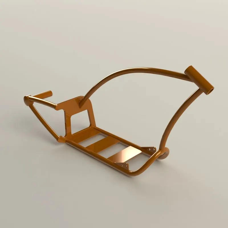
Features used to create Chassis:
- Sketch
- Project Curve
- Swept Boss
- Mirror
- Extruded Boss
- Extruded Cut
- Chamfer
- Fillet
- Dome
- Split
- Combine
- Revolved Boss
12. Engine
Engine is the powerhouse of the vehicle. It burns fuel to move the pistons which produce linear motion, the linear motion is then converted to rotational motion using the crankshaft. The output from the crankshaft drive the gearbox which finally drives the rear wheel that propels the vehicle forward.
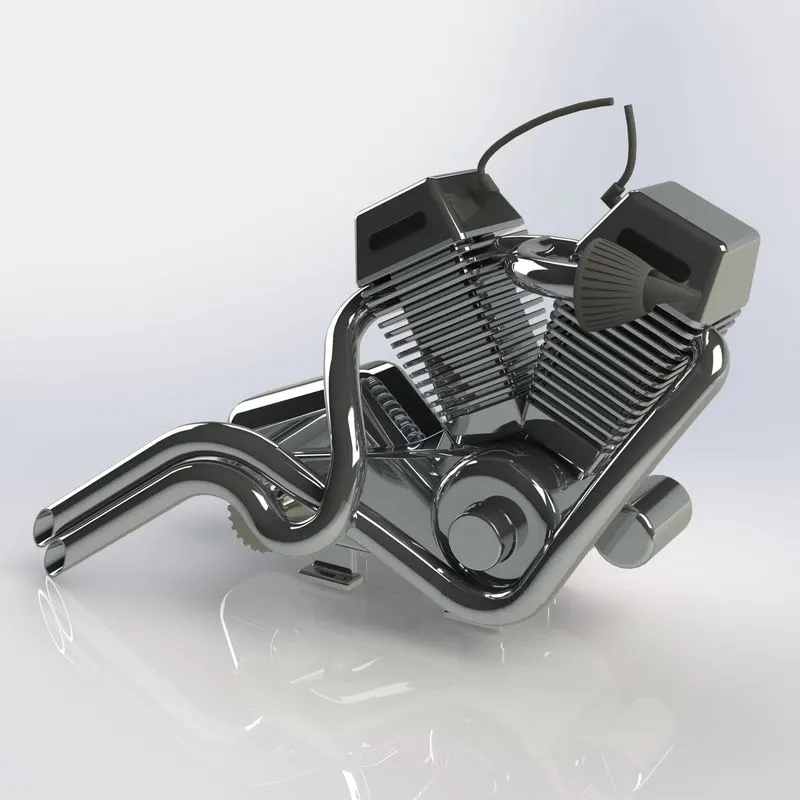
Features used to create Engine:
- Sketch
- Extruded Boss
- Fillet
- Revolved Boss
- Circular Pattern
- Dome
- Extruded Cut
- Chamfer
- Linear Pattern
- Mirror
- Split
- Swept Boss
- Project Curve
- Composite Curve
13. Gas Tank
It is also called as the fuel tank. As the name suggests, it is used to store fuel to run the engine.
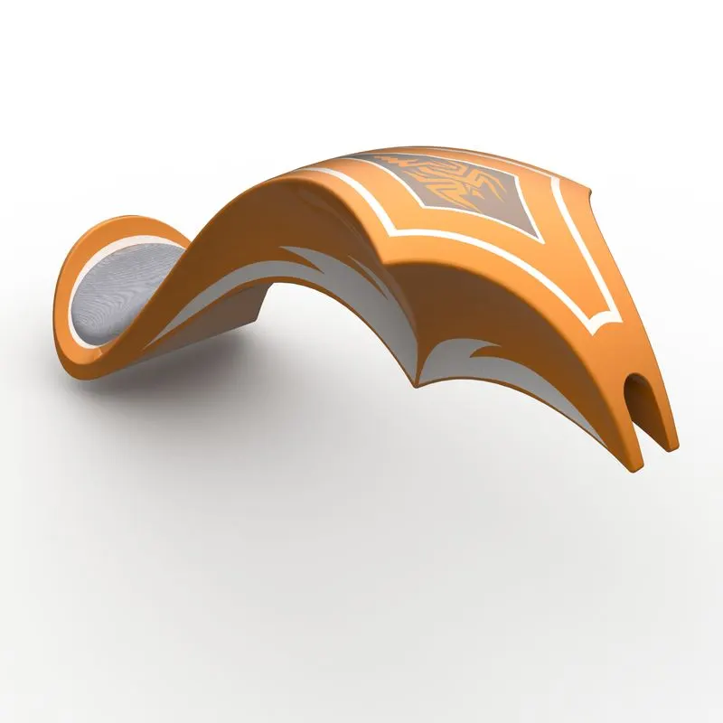
Features used to create Gas Tank:
- Sketch
- Swept Surface
- Trim Surface
- Project Curve
- Lofted Surface
- Boundary Surface
- Mirror
- Knit Surface
- Split Line
- Extruded Surface
- Fillet
- Swept Cut
- Shell
Assembly of Chopper Model
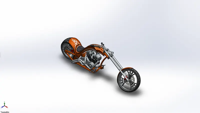
The Chassis is the first part that is imorted into the assembly environment. The rest of the parts are then constrained to the chassis. Once all the parts are fully assembled and constrained, it will look similar to the following images.
Front View of Assembly
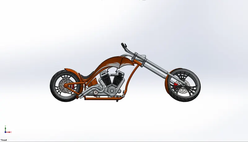
Side View of Assembly
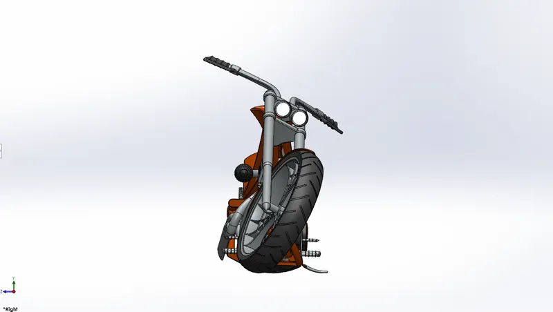
Isometric View of Assembly
Rendering of the Chopper Model
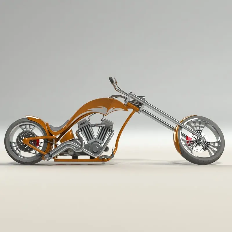
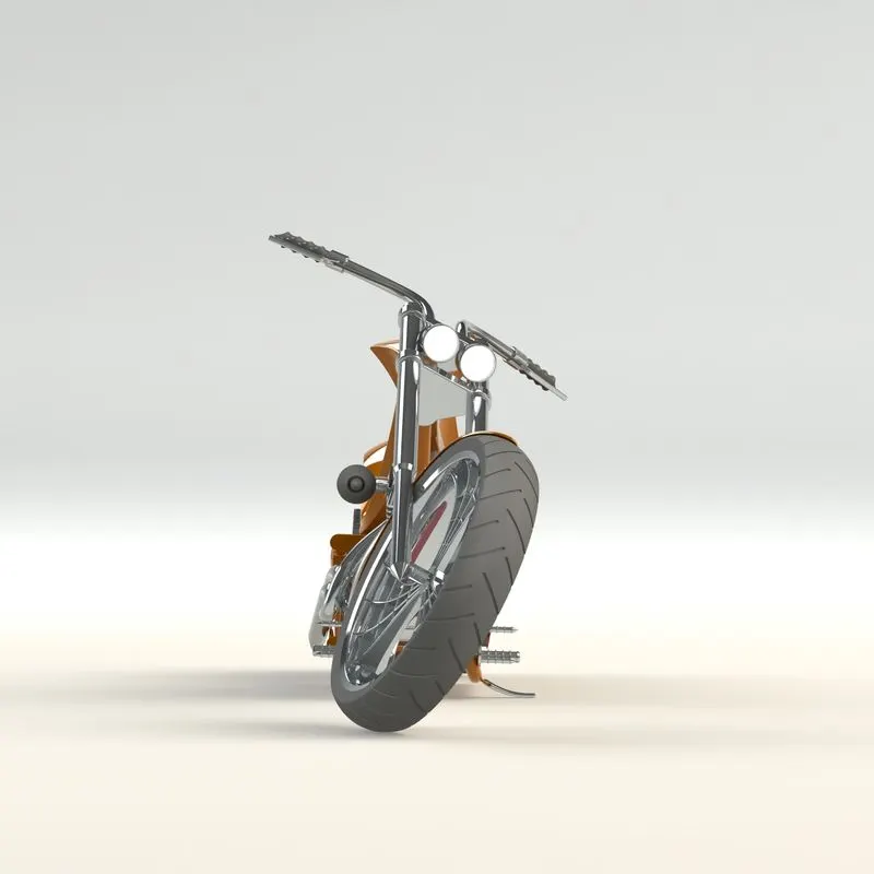
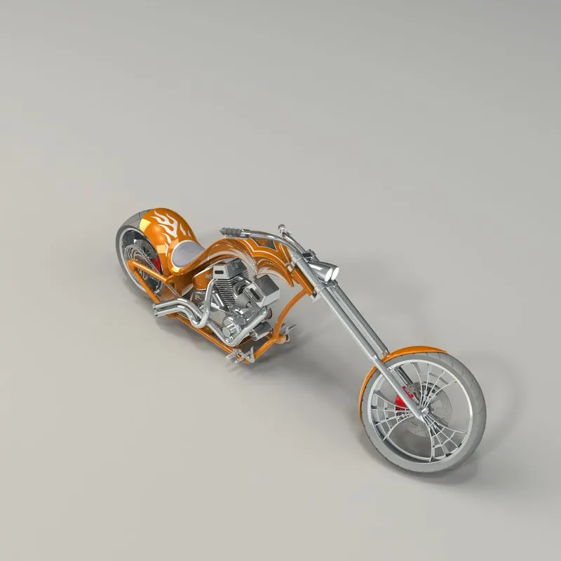
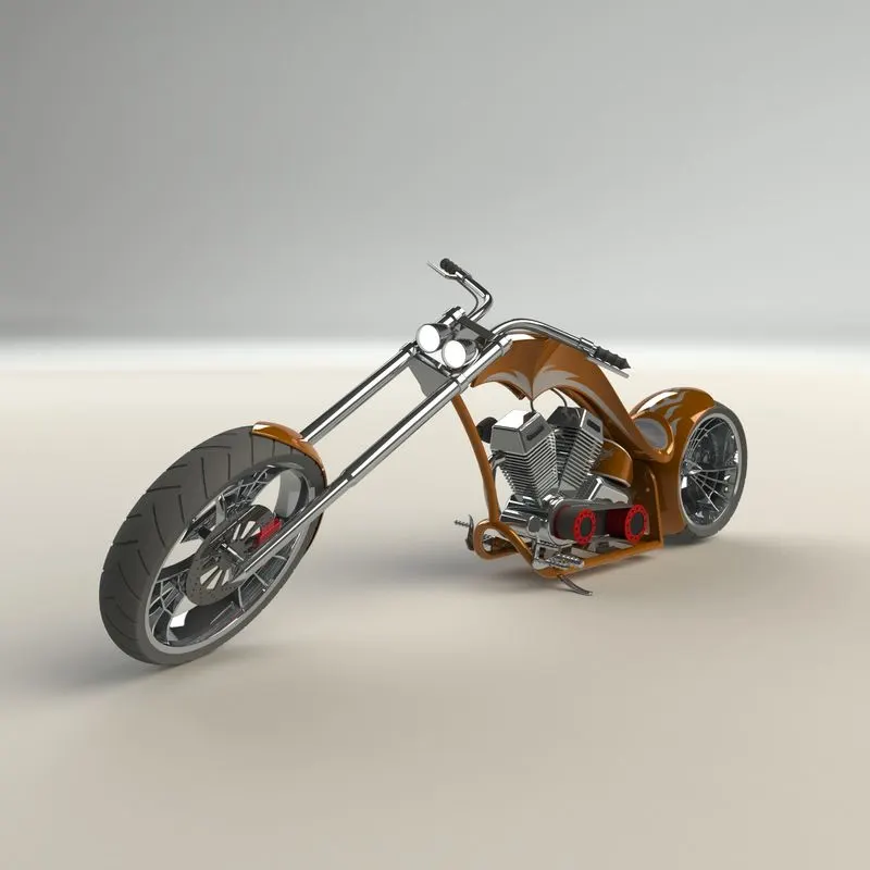
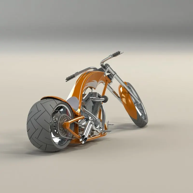
Rendering is the process of generating photorealistic images from a 2D or 3D model by means of a computer program. In rendering each and very aspects such as camera, lighting, environment, background, appearance plays a major role in the final render. The final render takes a lot of time to complete, so it is always better to use the preview window to get an idea of how the final render will look like and accordingly the various settings can then be tweaked to achieve the perfect final render.
Some of the final renders of the model are shown below,
Conclusion
- The parts are sketched and modelled in SOLIDWORKS.
- The modelled parts are assembled with full constrained mates and decals are applied to faces.
- The model was rendered using Photoview 360.