Photo Realistic Rendering
DESIGNING OF AMERICAN CHOPPER WITH PHOTO-REALISTIC RENDERING USING SOLID WORKS
OBJECTIVE:
The main objective of this project is to ideate for Design and AssembLy of an American Chopper using Solid works and photo realistic Rendering of AssembLy using photoview-360 and Solid works VisuaLize for understanding Mechanical Design process. Then Rendering is carried by adding proper decaLs, cameras, Lights and appearances.
INTRODUCTION:
In designing of any product first starts with an ideate and then convert these things into sketches by visualizing. Then these sketches are sent to designers for designing with proper dimensions by applying fundamentaLs of Engineering. These processes wiLL be carried out until the design satisfies the proper requirements of customer needs and design parameters. Then these are modeLLed using SoLid works by converting sketches into parts further these parts are joined together using Assembly for obtaining finaL product.
Solidworks is an 3D ModelLing Computer-aided design software developed by Dassault systems. It uses an principLe of 3d Parametric design and generates three kinds of interconnected fiLes: the part, the assembly, and the drawing. It heLps to perform easiLy ModeLLing by converting sketches(2D) to Parts(3D) easily using some Features. In Every part consists of sketches with appropriate dimensions using Required Geometries. Then by appLying Features which are nothing but required shapes to be formed based on sketches. ALL these parts are to be separated in a new foLder and then new assembly is seLected to insert in this environment. In AssembLy aLL these parts are assembLed together by applying mates to two different parts on basis of planes and some relations like coincident, parallel and concentric. Then separate foLder for mates is created to recognize easily reLation between two parts.
American chopper bikes are motor bicycles buiLt by Orange county choppers (0CC) for a specific corporate or celebrity customer. These bikes are motorcycLes in which the theme of the motorcycLe takes priority over everything eLse, influencing the frame dimensions, paint scheme, and overalL feeL of the motorcycle. The function of motorcycle usuaLly takes a backseat to the presentation of the theme, and these motorcycLes attract attention slowLy on the premise of the theme itself. Customer bikes are buiLt for and generalLy to the specifications of a particular customer. Although the customers typicaLLy give 0CC creative freedom to do what they will, some cLients have a specific idea in mind and expect 0CC to reproduce their mental picture Literally.
DESIGN APPROACH
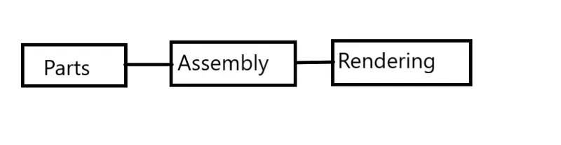
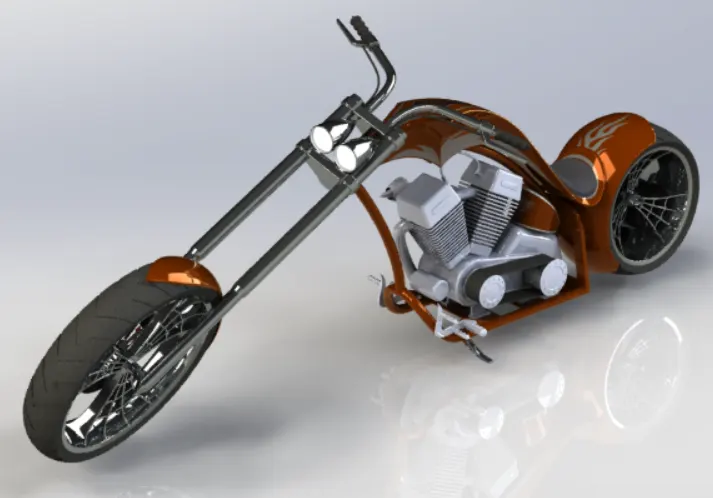
DESIGN METHODOLOGY
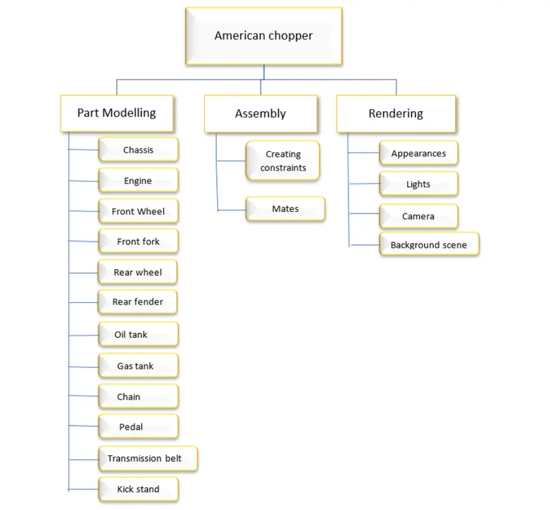
a.) Transmission Belt:
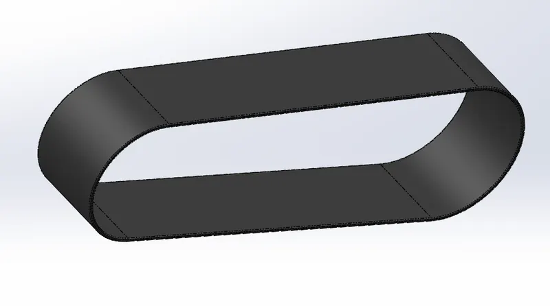
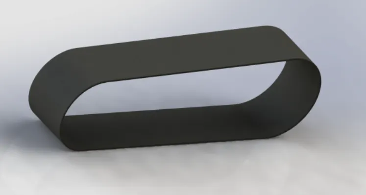
The transmission beLt is one of the mechanicaL elements to transfer the power between two or more rotating shafts.It consists of an fLexible strip with mostly made of rubber material. The one side of beLt drive is connected to the engine where as other side is connected to wheeL for transmitting power. It also modifies rotary motion in a easy way. There are nearLy five types of beLts, but it is seLected on basis of requirements Like diameter of wheel, design power, corrected power rating, pitch Length and center Distance etc. In some cases, these drives are used for change the speed, either up or down by using different sized puLLeys.
Commands used in sketch:
1. Line
2.Arc
- Smart Dimensions
- Properties
- Offset Entities
Commands used in Features:
- Plane
- Boss Extrude
- FiLLet
- Appearance
steps for Modelling Transmission belt:
- At first appropriate Plane is seLected and by using sketch feature lines, Arc are drawn by giving certain dimensions using Smart Dimensions.
- By using Properties arc and lines are arranged to be Tangent for each other on both sides. The entire sketch can be created once outside using command Offset
- The required plane is seLected and extrude the materiaL in between two sketches. The sharpness of edges are reduced using Fillet
- Appearance feature is used to specify particular material and add to the designed component.
b) Kick Stand:
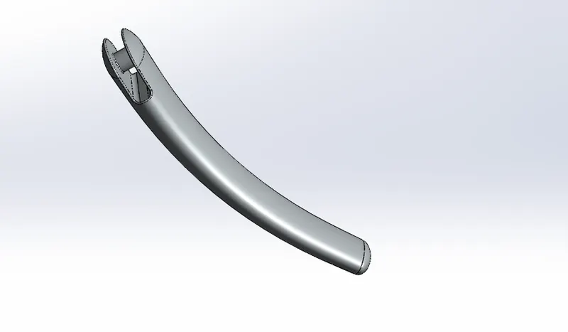
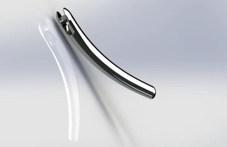
It is an one of the important component that carries whoLe body of vehicLes without faLling on ground during rest position. It is usuaLLy an piece of metal that can flips out from frame and makes contact with ground. MostLy kickstand are Located at left bottom just like as pedaLs and chain for a bicycle. The main reason is due to Location of exhaust in right side which can suffers one’s Leg during opening stand. The main reason that exhaust is Located on right because it is mount from Left. The kick stand is seLected on basis of frame and putting gears on scale to get estimate how strong.
Commands used in sketch:
- Line
- SpLines
- ELLipse
- CircLe
- Smart Dimensions
Commands used in Features:
- Creating plane
- Loft
- Dome
- Extrude cut
- SpLit
- Extrude Boss
- FiLLet
steps for Modelling Kick Stand:
- The required pLane is seLected and Ellipse is created by appropriate dimensions. By using Reference geometry other pLane is seLected and ellipse is created on this pLane. Required SpLine is seLected and joins the two eLLipses.
- The Loft feature is seLected to add materiaL between two eLLipses by adjusting guiding curves. By using Split command the unwanted materiaL is removed.
- At one edge the appropriate rectangle is drawn and by using extrude cut the materiaL is removed. The circLe is drawn and extrude is used to add material.
- By using Fillet options, the sharpness of edges is removed.
c) Front fender:
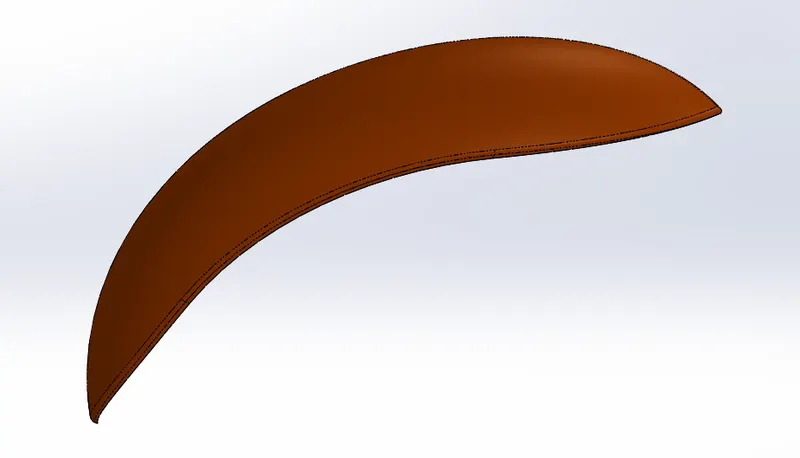
It is just like an protection Layer which Located just above the front wheeLit can protects during rain and heLp protect our Legs from spray of water during riding. The some of the important parameters for choosing front fenders is at Least 8mm wider than tire,1O-l2mm better.
Commands used in sketch:
- Lines
2.Arc
- Properties
- Smart Dimensions
- Offset Entities
- Trim
- Extend
- Splines
Commands used in Features:
- Axis
- RevoLve
- Split
- FiLLet
steps for Modelling Front Fender:
- The appropriate plane is seLected, and arc is created and both edges are made as horizontal. The appropriate dimensions are given.
- By using the Offset Entities, the whole sketch is drawn inwards. The edges are extended by using command Extend. The unwanted line is removed by using trim option.
- The reference axis created and by using Revolve option the whole sketch is revolved for some angle in both forward and reverse direction.
- The SpLines are drawn at both edges with required dimensions and unwanted material is removed by using Split
- By using Fillet option, the sharpness of edges is removed.
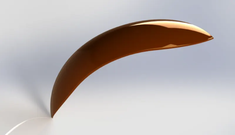
d) Rear fender:
The back fender is also same as front fender, but the width is more in back fender as the tire has more width. It stands as protection for avoiding water drops during rain or snowmelt.
Commands used in sketch:
- Lines
2.Arc
- Properties
- Smart Dimensions
- Offset Entities
- Trim
- Extend
- SpLines
Commands used in Features:
- Axis
- RevoLve
- FiLLet
- SheLL
steps for Modelling rear Fender:
- The appropriate pLane is seLected, and Arc is created, and both edges are made as horizontaL The appropriate dimensions are given.
- By using the Offset Entities, the whoLe sketch is drawn inwards of the sketch. The edges are extended by using command Extend. The unwanted Line is removed by using Trim
- The reference axis created and by using RevoLve option the whoLe sketch is revoLved for some angle in both forward and reverse direction.
- By using FiLlet option, the sharpness of the edges are removed.
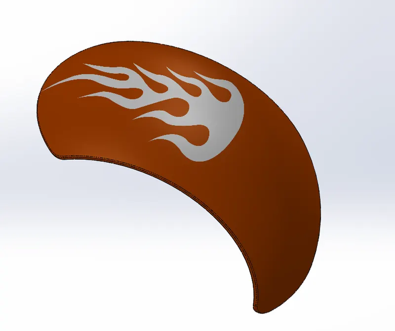
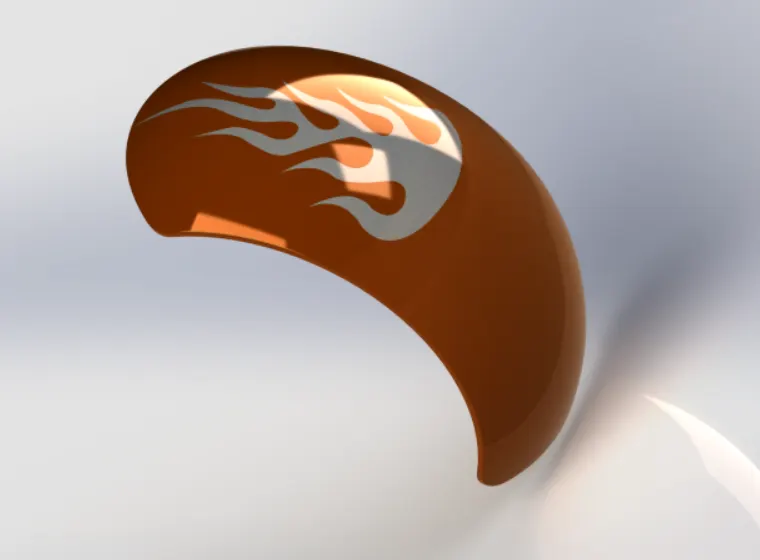
- The SheLL is used to hollow out the inside face of fender by using specified thickness.
e) Oil Tank:
It is a safe container to store fLuids such as petroL and diesel to be maintained without fLaming. It can vary in size from as LittLe as from two gallon whiLe others big as eight gaLLons. These tanks aLLow the fLuid to fLow through engine and starts ignition. These tanks are mostLy used in automobiLe appLications and aerospace industries use for storing high temperature integraL fLuids. Some fueL tanks like metal are made weLded from stamped sheets whiLe others Like pLastic fuel tanks made by using bLow moLding.
Commands used in sketch:
- Lines
- Properties
- Splines
Commands used in Features:
- Boss Extrude
- Combine
- Fillet
- SheLL
- Appearance
steps for Modelling Oil Tank:
- The required pLane is seLected to draw sketch to draw required geometry Like lines, arc with appropriate dimensions by adding properties.
- Then whoLe is extruded to add material and then sketch is drawn on body with required dimensions.
- Extrude the sketch for adding materiaL on both sides then select the Combine Feature(common)to combine two features of body.
- FilLet is added to edges of body to remove sharpness. The SheLl feature is added to body to remove inside materiaL and thickness the sides of materiaL with required dimensions.
- The required materiaL is added to both Fillet and body separateLy by using Appearance.
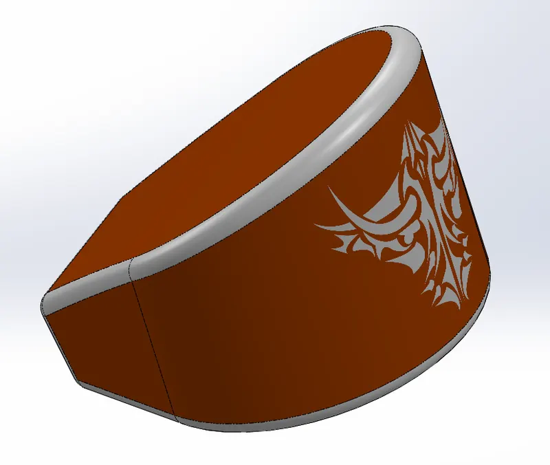
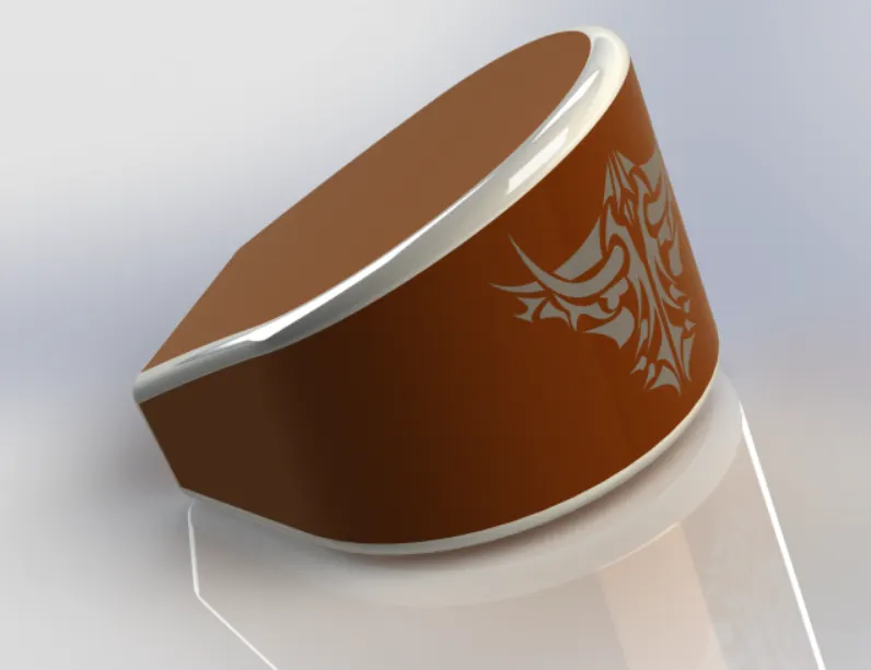
f) Pedal:
It is an one of the part of bike to start the vehicLe that pushes by rider on it. It works on rotationaL force as pushing the pedals forward then they turn the gears that are attached to chain. The best pedal with low weight provides better safety. Some of the types of pedaLs are FLat, Cage and ClipLess.
Commands used in sketch:
- Line
- CircLes
- Properties
- SpLines
- FiLLet
Commands used in Features:
- Boss Extrude
- FiLLet
- RevoLve
- Chamfer
- Linear pattern
steps for Modelling PedaL:
- The required pLane is seLected for creating sketch with required geometries such as Lines, circles and spLines. Then f iLLet is added to edges portion in sketch.
- Then Extrude the required sketch to add materiaL.
- Required pLane is seLected to draw sketch then Revolve the whoLe sketch. The Dome is seLected on one edge to make the shape of concave.
- The appropriate edges are seLected to do Fillet for removing sharp edges. Then Chamfer is seLected to convert edges into point.
- The Linear pattern is seLected to make the required bodies at certain positions with required numbers.
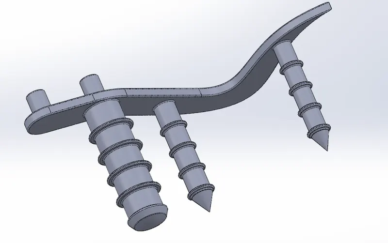
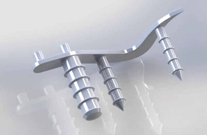
g) Chain:
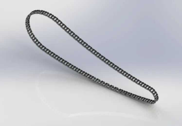
It is an roLler chain that provides transfer of power from engine to wheeLs and the power driven by roLLer chain are known as drive chain or transmission chain. It causes the gear that drives a wheel to rotate more than one revoLution. These chains are made of muLtipLe pairs of steeL both outer and inner pLates and pins are inserted between them. The roller separates each pair of inner pLates. Mostly chains are made of materials like pLain carbon or aLLoy steeL, but some are nickel pLate to prevent from rust.
Commands used in sketch:
- CircLe
- Lines
- Properties
- Arc
5.Trim
- Properties
Commands used in Features:
- Boss Extrude
- BLocks
- Linear pattern
- FiLLet
- Mirror
- Appearance
steps for Modelling Chain:
- The required pLane is seLected then sketch is drawn with appropriate geometries like Lines and Arcs with required dimensions.
- Two chain plates are drawn by using Blocks command make them as separate in new foLder. Then open the sketch and browse two pLates then place them at required positions by using properties Like Concentric and Coincident.
- Then use linear pattern seLect the pattern curve as required Line with appropriate number of chain plates. Add FiLlet to edges of pins to remove sharp edges.
- Select other geometry pattern and follow same as above steps. Then separate the Pins into one foLder and Chain pLates into other foLder for easy selection.
- Then seLect chain pLates and Mirror it towards front plane to form chain pLates at other side. By using Appearance add required material to chain.
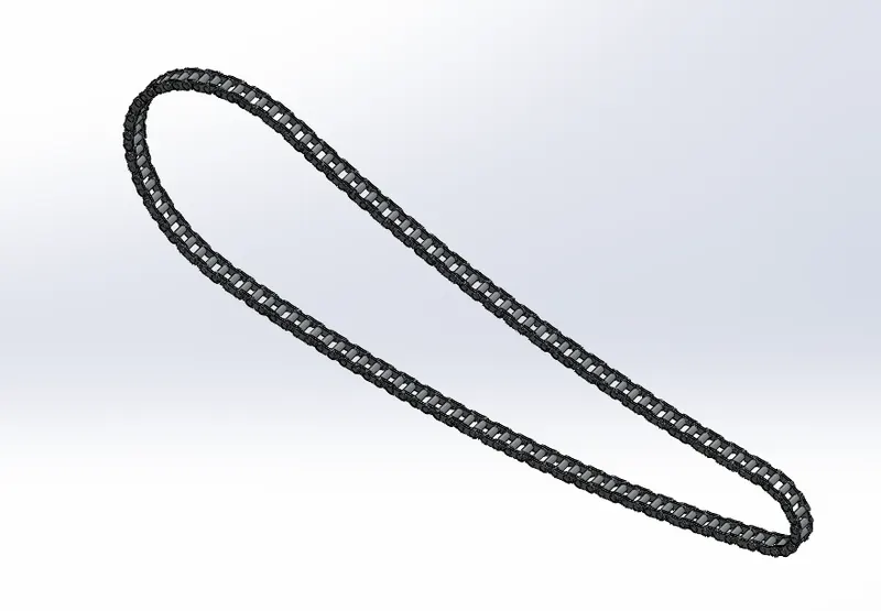
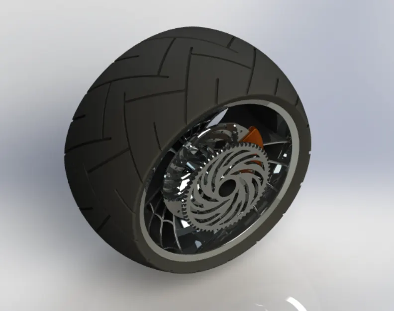
h) Front wheel:
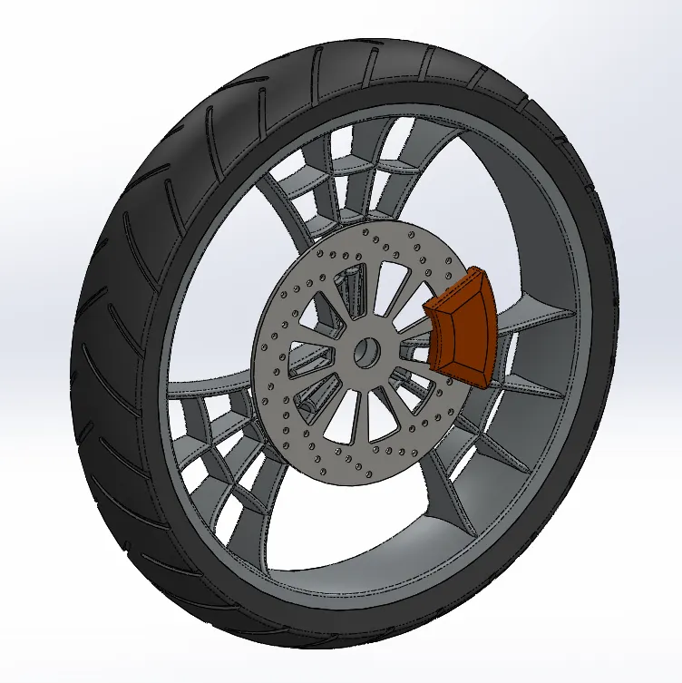
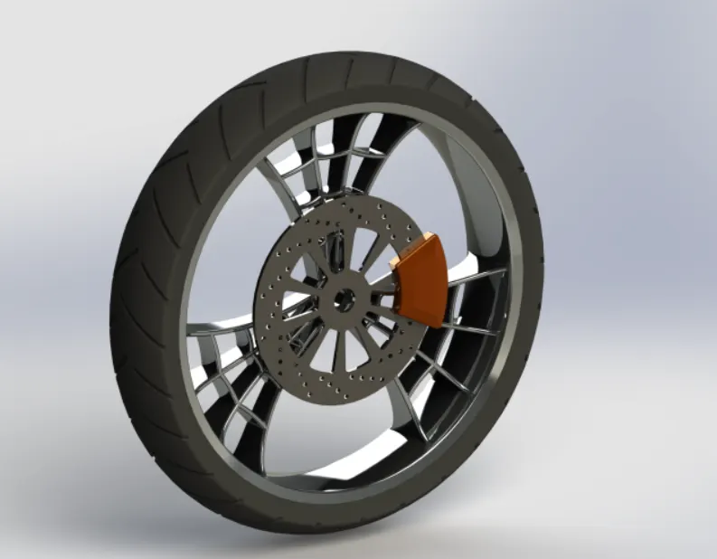
It is a wheeL designed for bike to support the front body of bike. In this spider webbed spokes are used. These spokes are connecting rods between rim and hub. The main work of spokes is to transfer the Loads between rim and hub which causes due to weight of rider. The increasing wheel size wiLL decrease the diving force from wheeLs which resuLts in decrease in acceleration of wheels.
Procedure for ModeLling Front Wheel:
Rim
It is an outer edge of a wheeL that hoLds the tire on the wheeL. The main function of rim is to support and sealing the tire to wheeL. It ensures that proper fitting between tire and rim. Rims are important parts as they rotates around rods that are caLLed axLes.
Commands used in sketch:
- Line
- Arc
- SpLines
- Properties
- FiLLet
- CircLes
- Convert Entities
- Mirror Entities
- Offset
- Trim
Commands used in Features:
- Extrude Bose
- Extrude Cut
- RevoLve
- Linear pattern
- RevoLve Cut
- Combine
- FiLLet
steps for Modelling rim:
- The required pLane is seLected and geometries Like Lines and arcs are drawn with appropriate dimensions.
- Then RevoLved Base is seLected to revoLve the whoLe geometry by selecting axis. Then pLane is seLected to draw spokes with appropriate sketch. By using Mirror required geometries are get copied.
- Then it is extruded to add materiaL. The geometry is seLected and Extrude cut to remove materiaL for spokes. By using Linear Pattern, the spokes are increased around outer circLes. Then required materiaL is added to Rim.
Rotor
It is a circuLar disc that connected to each wheeL. These are designed to turn kinetic energy into thermal energy. When the calipers squeeze the brake pads together then surface area creates friction.
Commands used in sketch:
1.CircLe
- Lines
- Properties
Commands used in Features:
- Extrude Boss
- Chamfer
- FiLLet
- Extrude cut
- Linear pattern
steps for Modelling Rotor:
- The required pLane is seLected, and circLe is drawn then Extrude it to add material. CircLe is drawn on this phase. To increase these number of circLes Linear Pattern sketch is seLected.
- Then these circLes are gets Extrude Cut. Then Linear Pattern is seLected aLong circuLar shape.
Caliper
The job of caLipers is to sLow down the bike wheeLs by creating friction with brake rotors. Inside each CaLiper there is a pair of metal pLates known as brake pads.
Commands used in sketch:
- CircLe
- Trim
- Properties
Commands used in Features:
- Extrude boss
- FilLet
- Champers
steps for Modelling caliper:
- Two circles are drawn on phase of rotor. Then required Lines are drawn to connect these circles.
- These geometries is selected to get Extrude for adding material and edges are applies Chamfer and Fillet.
Tire
Tire is an external protection of rim which touches ground. It is a strong and flexibLe rubber casing that attached to rim of a wheel. Natural rubber is an material used for manufacturing tire.
Commands used in sketch:
1.Arc
- Rectangle
- Lines
- Properties
- Fillet
Commands used in Features:
- Revolve
- Extrude Cut
- Linear pattern
- Fillet
steps for Modelling tire:
- Requires geometry is drawn and fiLLet is drawn at edges. Then the sketch is selected to Revolve.
- Some rectangLes are drawn on phase with required dimensions. Then these are applied Extrude cut. Fillet is applied to Edges.
- Then Linear Pattern selected for circular and all these rectangles are applied around the circular path.
i) Rear wheel:
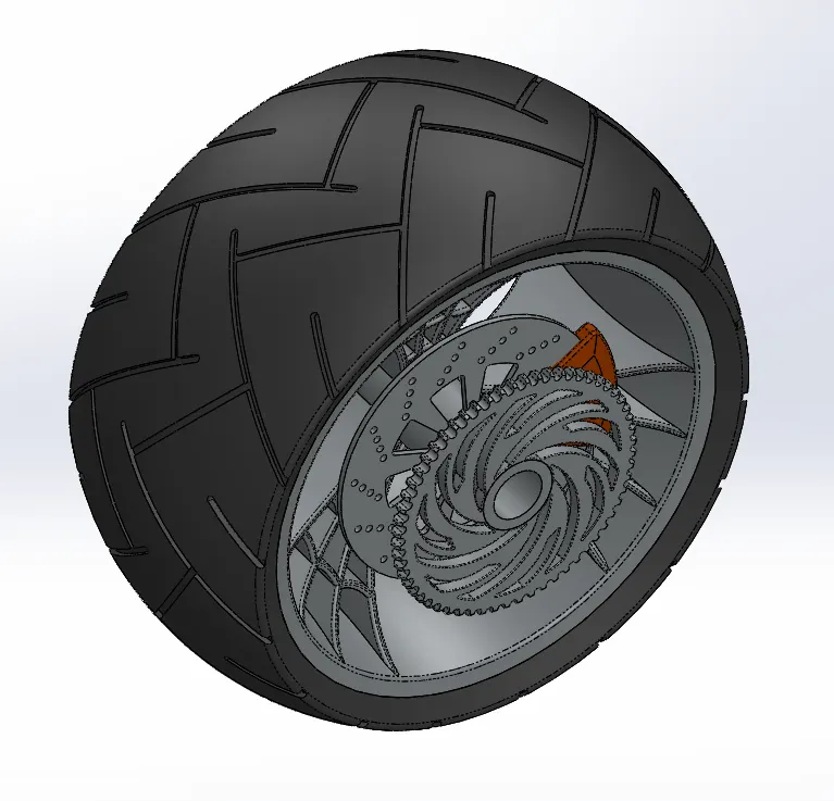
It is a wheeL designed for bike to support the Rear body of bike. In this spider webbed spokes are used. These spokes are connecting rods between rim and hub. The main work of spokes is to transfer the loads between rim and hub which causes due to weight of rider. The increasing wheeL size wiLl decrease the diving force from wheeLs which results in decrease in acceLeration of wheels.
Procedure for ModelLing Rear Wheel:
Rim
It is an outer edge of a wheeL that holds the tire on the wheeL. The main function of rim is to support and seaLing the tire to wheel. It ensures that proper fitting between tire and rim. Rims are important parts as they rotates around rods that are caLLed axLes.
Commands used in sketch:
- Line
2.Arc
- Splines
- Properties
- FiLLet
- CircLes
- Convert Entities
- Mirror Entities
- Offset
- Trim
Commands used in Features:
- Extrude Bose
- Extrude Cut
- RevoLve
- Linear pattern
- RevoLve Cut
- Combine
- FiLLet
steps for ModeLLing Rim:
- The required pLane is seLected and geometries Like lines and arcs are drawn with appropriate dimensions.
- Then Revolved Base is seLected to revoLve the whoLe geometry by seLecting axis. Then pLane is selected to draw spokes with appropriate sketch. By using Mirror required geometries are get copied.
- Then it is Extruded to add materiaL The geometry is selected and Extrude Cut to remove materiaL for spokes. By using Linear Pattern, the spokes are increased around outer circles. Then required material is added to Rim.
Rotor
It is a circuLar disc that connected to each wheeL These are designed to turn kinetic energy into thermaL energy. When the caLipers squeeze the brake pads together then surface area creates friction.
Commands used in sketch:
- CircLe
- Lines
- Properties
Commands used in Features:
- Extrude Boss
- Chamfer
- FiLLet
- Extrude cut
- Linear pattern
steps for Modelling Rotor:
- The required pLane is seLected, and circLe is drawn then Extrude it to add materiaL. Circle is drawn on this phase. To increase these number of circLes Linear Pattern sketch is seLected.
- Then these circles are gets Extrude cut. Then Linear Pattern is seLected aLong circular shape.
CaLiper
The job of caLipers is to sLow down the bike wheels by creating friction with brake rotors. Inside each CaLiper there is a pair of metaL plates known as brake pads.
Commands used in sketch:
- CircLe
- Trim
- Properties
Commands used in Features:
- Extrude boss
- FiLLet
- Champers
steps for Modelling caliper:
- Two circLes are drawn on phase of rotor. Then required Lines are drawn to connect these circLes.
- These geometries are seLected to get Extrude for adding materiaL and edges are appLies Chamfer and Fillet.
Sprocket
It is a chainwheeL which is profiLed wheeL with teeth’s around its circuLar pattern. The chain is attached to this wheeL which for easy transmission of power to Rear wheeL.
Commands used in sketch:
- Line
- CircLe .
- SpLines
- Properties
- Trim
Commands used in Features:
- Extrude boss
- Linear pattern
- Extrude Cut
- FiLLet
steps for Modelling sprocket:
- The required profiLe is selected to sketch the geometry with appropriate dimensions. The circLes are Extruded for adding material.
- The spLines are drawn for required profile then unwanted geometry is removed by using trim. The profiLe is seLected for Extrude cut to remove materiaL.
- Then Linear Pattern is seLected to get a greater number of profiLes. The FiLLet is applied at edges to remove sharpness.
Tire
Tire is an externaL protection of rim which touches ground. It is a strong and flexibLe rubber casing that attached to rim of a wheeL. Natural rubber is an materiaL used for manufacturing tire.
Commands used in sketch:
- Arc
- RectangLe
- Lines
- Properties
- FiLLet
Commands used in Features:
- RevoLve
- Extrude Cut
- Linear pattern
- FiLLet
steps for Modelling tire:
- Requires geometry is drawn and fillet is drawn at edges. Then the sketch is seLected to Revolve.
- Some rectangLes are drawn on phase with required dimensions. Then these are applied Extrude cut. FiLLet is appLied to Edges.
- Then Linear Pattern selected for circuLar and aLL these rectangles are applied around the circuLar path.
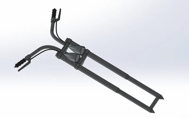
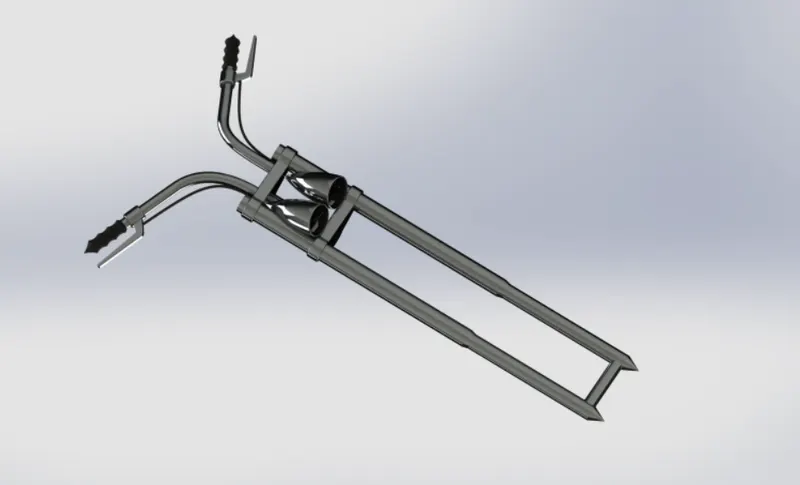
j) Front Fork:
It is a part of bike that hoLds the front wheel. It consists of two blades which are joined together at top by fork crown. It works Like the front suspension on motorcycle. It absorbs shocks which has springs on it due to this can feeL comfortabLe during traveLLing on uneven roads. It has good benefits during riding on speed breakers, so it is better to have front fork.
Commands used in sketch:
- Lines
- Sptine
- CircLe
- Properties
- Convert Entities
- Trim
Commands used in Features:
- Revolve Boss
- Extrude Boss
- FiLlet
- Revolve
- Linear Pattern
- Extrude Cut
- Dome
- Revolve Cut
- Sweep
- Mirror
- Combine
- Planes
- Appearance
steps for Modelling Front Fork:
- The required plane is selected for drawing the sketch with appropriate dimensions. Then by using Revolve command select the required sketch to revolve and add material along its axis.
- Then at one edge required sketch is drawn and it is extruded to add material The sharped edges are removed by using fillet option. By using Linear Pattern the required part is selected at required position to form it again.
- At the one edge circle is drawn and Extrude it to add materiaL To create head lights the required geometry is drawn on selected plane and Revolve it around the axis.
- By using Swept Boss, the required path and circle is selected to follow circLe along the path for required handle to be drawn. To form gripper at edge of handle the geometry with circles is drawn and revoLve it along its base.
- To draw brakes required geometry with linear are drawn with appropriate dimensions then it is extruded to add material Two circles are drawn at two different planes and by using spline thy are connected. The sweep is selected to follow circle aLong spline to form wire shape.
- By using Mirror, the whole body is selected and formed again along its side. The required Appearances are added for different parts.
k) Chassis:
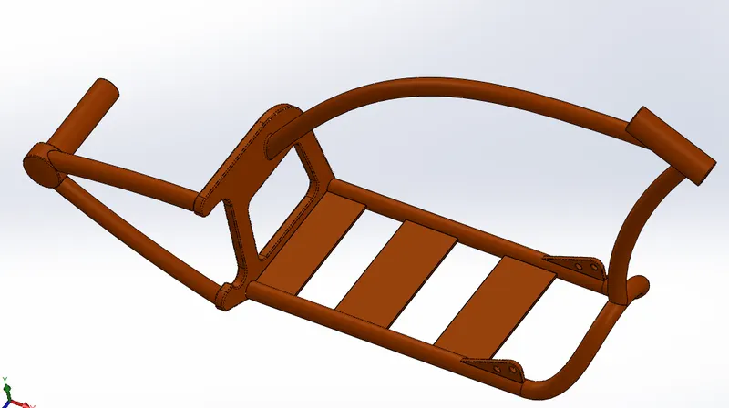
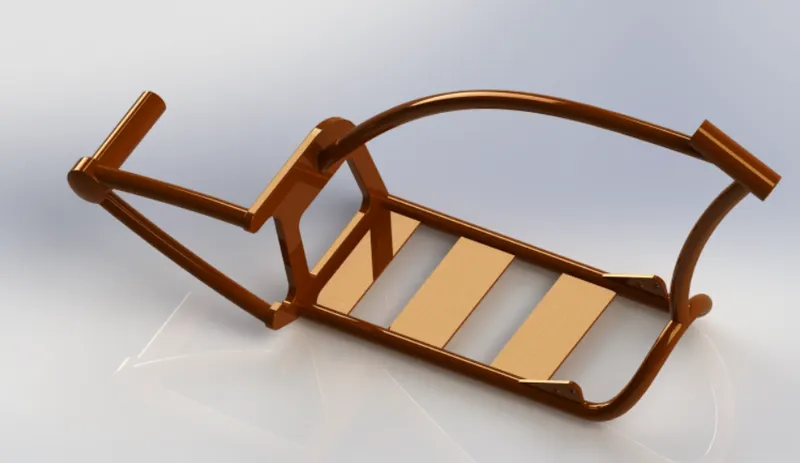
It is a Like metaL frame which forms as a skeleton for mounting components on it. ALL components Like Engine, suspension, fuel tanks and seats etc. are attached to this base. On basis of different bikes usage of materiaLs also can change. Some of the materiaLs Like steel, titanium and magnesium with requirements Like cost, stiffness and speed are used.
Commands used in sketch:
- Splines
- Circles
- Lines
- Sketch picture
5.Arc
Commands used in features:
- Sweep
- Mirror
- Boss Extrude
- Extrude cut
- Chamfer
- FilLet
- Plane
- Dome
- Split
- Combine
- RevoLve
- Curves
- Appearance
steps for Modelling Chassis:
- The required p[ane is selected then by using sketch picture command required for inserting picture in solidworks environment for sketching. Then required positions and dimensions for picture are set by double clicking on photo.
- Then from Lower edge of chassis sketching is started by creating some circLes. Then Lines are drawn along the chassis that connects concentric circles. These Lines are projected by using Project curves Some geometries are drawn on top plane by using Splines with appropnate dimensions and it is projected.
- By using Swept Boss these profiLes are selected to follow path certain path and add material along the selected path. Then mirror option is selected to get the same part on other side by choosing front pLane as reference.
- The above drawn two profiLes are joined back with a pLate which is creating as foLLows. The above profiLe ends at right plane which is good reference for starting our new sketch. Then required geometry is drawn on this plane by using some Lines and CircLes with adding appropriate properties and extrude it to add materials. The geometry is drawn on this pLate and selected Extrude Cut to remove materiaL.
- Required chamfers and fillets are added to these pLates. Plane is created to draw a profiLe that connected rear wheeL which is known as Axle. The inside of this axLe circLe is drawn and extrude it that insert into wheeL. Then dome is seLected to outside edge of axLe to create good profile.
- Splines are drawn on front pLane with a good profiLe along the chassis in picture. Then concentric CircLes are drawn by using swept boss materiaL is added aLong this path Like structure to form for chassis. By using split tool some of the portions that enters into plates are removed by using profiLe of plate and cut profiLe of tubes from axLe.
- In a same way aLL required structures are drawn by using circLe profiLes and spLines that connect with this circle. Then swept boss is selected to foLLow profiLe on path.
- At above the below chassis part some profiles are drawn, and these are extruded to form as a basis for mounting Engine on it. In same way some required profiLes are drawn and extruded on basis of sketch in picture. FilLets are added at required positions to reduce sharpness. Appearance is seLected and required materiaL is added to chassis.
l) Engine:
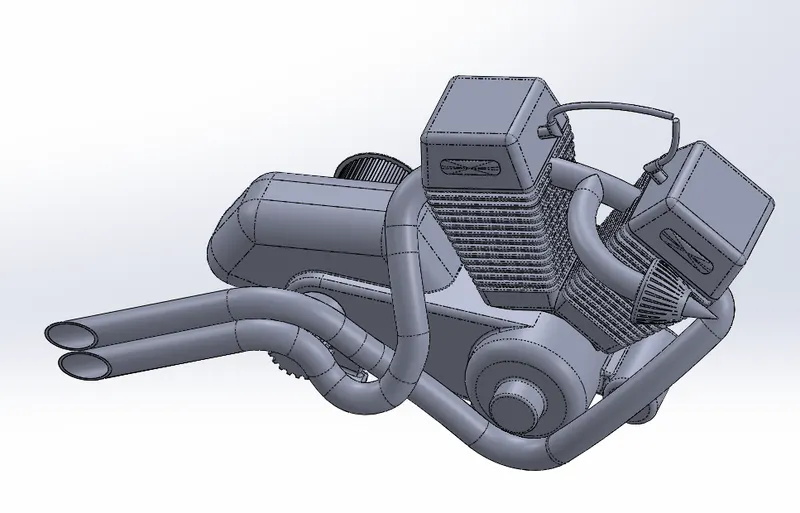
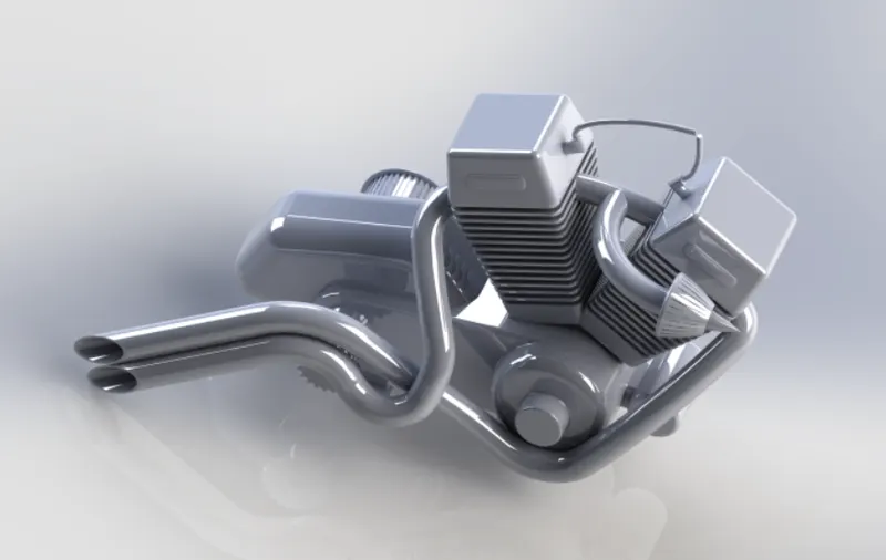
It is a machine used to change one form of energy into mechanicaL energy. It is a complex machine which is buiLt to convert heat from burning gas into force for turning wheeLs. These energies can be in a form of petroL or dieseL where a chemicaLs are used to produce energy. The chain of reactions which achieve the objectives is set in motion by spark, which ignites a mixture of petroL vapor and compressed air inside a cyLinder and causes it to burn rapidLy. It contains a cyLinder head contains vaLve-controLLed passage through which air and fueL mixture enters the cylinder. So due to this the engine must be a robust structure. The overaLL efficiency is around 35 percent. Some of the main parts included in Engine are piston, Camshaft, fLywheeL, crank shaft and connecting rods. Different Engines are In-Line Engine, V-8 Engine and HorizontaLLy opposed Engine.
Commands used in sketch:
- Sketch picture
- Circtes
- Splines
- Lines
- Properties
- Arc
Commands used in Features:
- Boss Extrude
- FiLLet
- RevoLve
- PLane
- CircuLar pattern
- Dome
- Extrude Cut
- Chamfer
- FiLLet
- Sweep
- Mirror
- Combine
- Curves
- Split
steps for Modeling engine:
- The suitable pLane is seLected, and picture is inserted by using sketch picture CircLes are drawn at require positions based on picture and both joined by using lines. Then whoLe thing is extruded to add material. Required profile is drawn besides this and extruded it with required dimensions.
- Some geometry is drawn and revoLve it to get required feature as reference to picture. On this profile some CircLes are drawn and seLected circuLar pattern to increase the number of Circles and extrude cut it to remove materiaL.
- In same way other required profites are drawn and appLied required features. The CyLinder profile is started by drawing rectangLe on top plane and seLected to Extrude it by giving some draft angLe. Some f ilLets are added to get required profiLe.
- To get another CyLinder the earLier cyLinder is seLected, and it is Mirrored aLong front pLane. Some rectangles are drawn on above cyLinder and extruded it by Appling fillet at corners and select dome to this profiLe. To draw spark, pLug geometry is drawn aLong profiLe and extrude it.
- To modeL Exhaust required profile with splines and arcs are drawn at required pLanes and these are projected by using curves. Then concentric CircLes are drawn, and these curves are intersecting with pierce
- Then by using Swept Boss the profiLe is created by foLLowing required path. In same way other Exhaust tube from another cyLinder is also modeLLed. The edge of Exhaust is cut by using some Lines to get good profile.
m) Gas Tank:
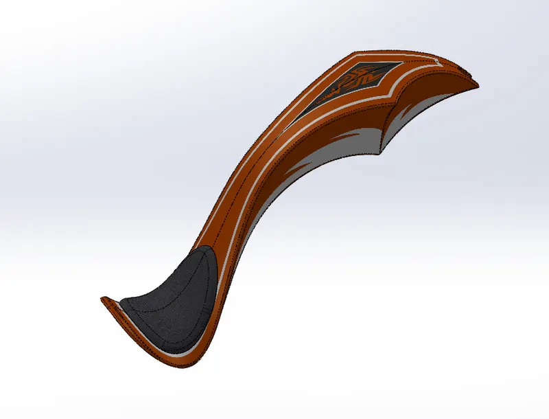
It is a safe container for storing flammabLe fLuids. It is usuaLLy placed above the engine and in direct to sunLight, so they are susceptible to fueL expanding with heat which pushes more fuel.
Commands used In sketch:
- lines
- Splines
- Sketch picture
- Convert Entities
- Offset
6.Arc
- Trim
Commands used In Features:
- Planes
- Mirror
- Sweep Cut
- Shelt
Commands used In Surfaces:
1 Sweep surface
2-Trim Surface
3 Surface Loft
- Prqected Curve
- Boundary surface
- Knit
- Split Une
- Extrude Surface
- Fitlet
Steps for ModellIng Gas Tank:
- The required plane is selected for inserting image then sketch is created on plane by using required geometry. Splines are selected and adjusted for required design by giving dimensions to create Gas Tank.
- By using Reference Geometry some plane is created at some distance from one end of sketch. Then splines are created on this plane and some other geometry for reference. Swept surface is selected for creating surface along the required path.
- The unwanted surfaces are tried by using trim surface command. By using surface Loft required portion is added for creating surface. By using the plane which is created required sketch is drawn by applying proper dimensions.
- Above sketch is selected and project it by using projected Curve. Then end points are joined using lines by applying pierce By using boundary surface required space is selected to create surface over it.
- Then mirror is selected along midplane to form same part on other side of Gas Tank Knit is selected to combine all the surfaces together.
- The seat is designed by selecting outer edges then offset is selected to form the same geometry. The arc is drawn by connecting both sides of geometry to form required shape. The above geometry is selected, and split line applied to form on surf act Then Extrude surface is selected to add materiaL Fillet is applied to reduce sharp edges. The bottom portion of tank is added surface by using Boundary Surface.
- Some geometry is drawn on required plane then Cul sweep is used to remove material. Then shell is applied to remove inside portion and make as thin material just like hollow part with required dimension.
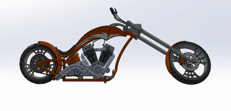
AssembLy of Designed Components:
Steps to FoLlow - AssembLy of Chopper:
- Step - 1: All the Parts/Components which are designed in Part fiLe are to be inserted in AssembLy fiLe one by one as per requirement.
- Step - 2 : AppLy Mates to each and every individuaL Part with other parts for proper ALignment.
- Step - 3: AppLy Mates Conditions to WheeLs and Kick Stand with Top PLane to Snap it fLoor.
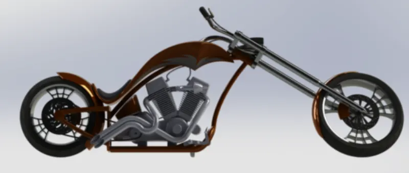
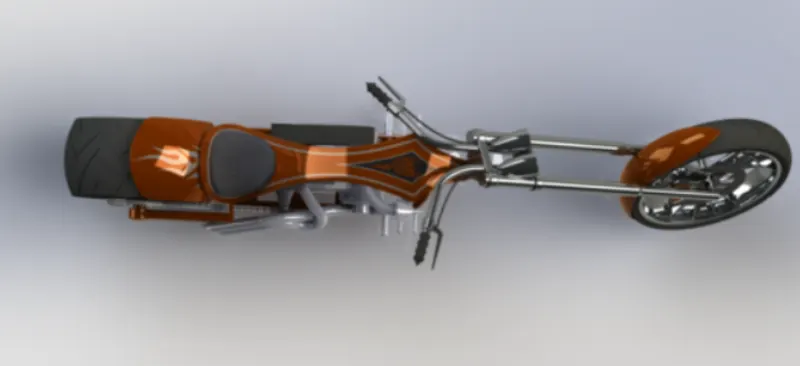
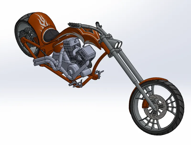
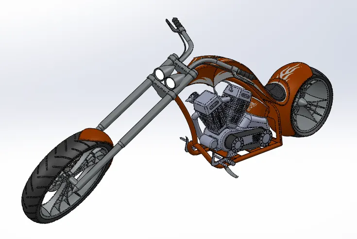
Render Image: Photoview 360
Side view
Back view
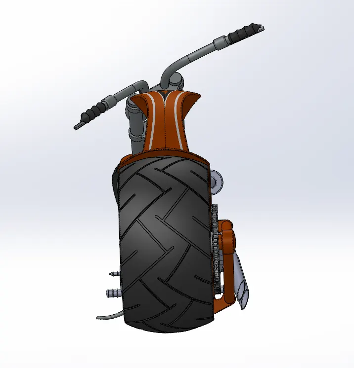
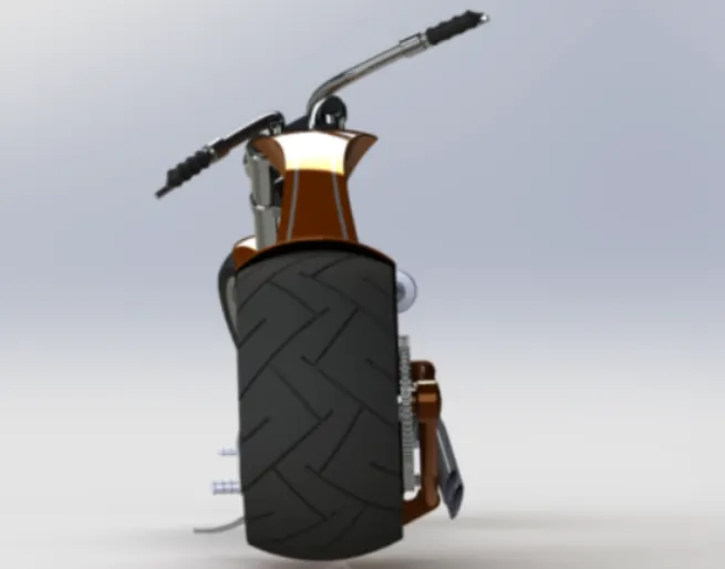
Front view
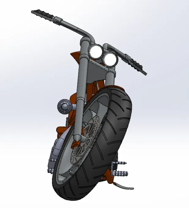
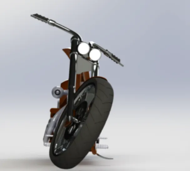
Top view
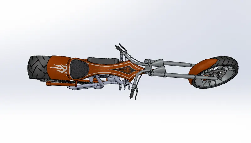
Isometric view
Camera view
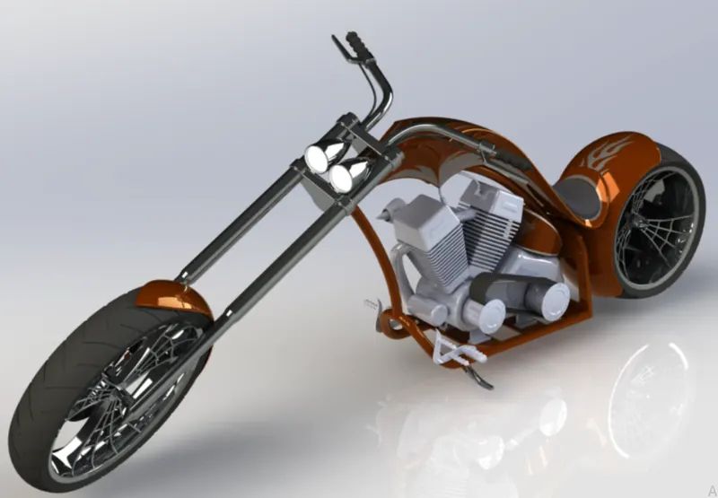
Applying Decals, Camera Set-up & Scences:
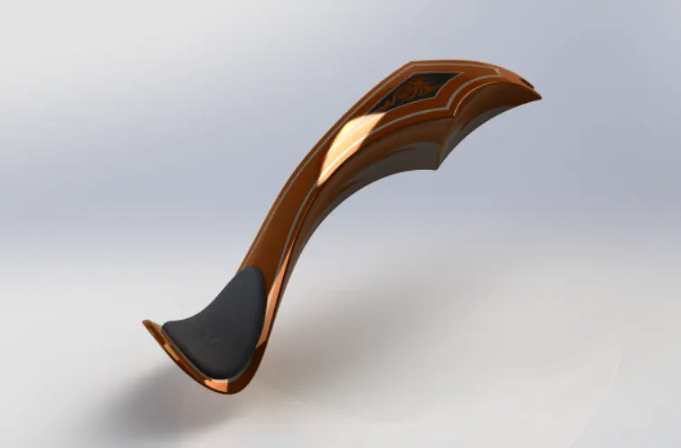
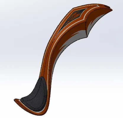
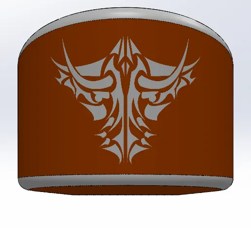
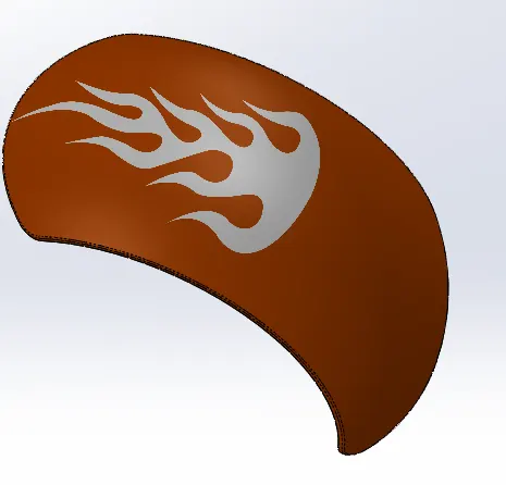
Applying Decals: In this section Decats (a design prepared on SpeciaL Paper) are appLied to Gas Tank, OiL Tank & Rear Fender.
Render Image: Photo View 360
Camera Set-up:
Camera Set-up is essentia[ for the final rendering of Chopper which heLps in showcasing the reaListic image.
Scenes & Lights:
Check for Appropriate scenes & proper Light set-up to make our Chopper realistic in finaL rendering.
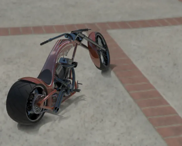
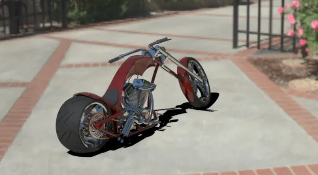
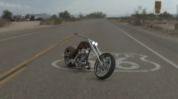
Final Rendering:
In this we are going to render our Chopper to make it ReaListic.
Software used: So[idworks Photo visuaLize.
Steps to Follow:
. Import - Import the Assembly file into the SoLidworks Photo VisuaLize.
. Appearance - Give/Change Appearance to Parts to make it more reaListic.
. Scenes - Add scenes (Environment -3D! Plate - 2D) as a background & choose proper location.
. Output - Make a fast render & check the output. Ones satisfied with everything go for FinaL quality rendering.
CONCLUSION:
At the end of Project, each and every component designed individuaL[y in part file and assembLed them to complete Chopper Design. AdditionaL Appearances/setup like Deca[s, Scenes, Camera, Lights, etc.. given to make it more realistic & FinaLLy Rendered after placing designed Chopper in decent background Scenes.