Advanced Sheet Metal Design Using NX Cad Challenge_6_Bracket
Advanced Sheet Metal Design Using NXCAD (Challenge 6 Bracket)
Objective:
The objective of this challenge is to create a “Bracket” using different types of tool/features.
What is NX CAD?
NX CAD is an advanced high-end CAD/CAM/CAE software used for designing models etc. It was formerly known as unigraphics owned by Siemens PLM Software.
What is Sheet Metal ?
Sheet metal is a thin and flat piece of metal formed by rolling or hammering, sheets are available in many different metals, namely aluminium, copper, brass, steel, gold, sliver, etc.
Tools used to create the Bracket:
- Sketch
- Contour Flange
- Normal Cutout
- Break Corner
- Unbend
- Rebend
- Simple Hole
- Flat Pattern
Here,
- Sketch: This command is used to draw sketch of the required shape design.
- Normal Cutout: This command is used to create a cutout by projecting a sketch upon the model and then cutting perpendicular to its face by the projection.
- Unbend: This command is used to unbend the whole model into a flattened sheet.
- Rebend: This command is used to rebend all the joints as previously state to make the sheet metal model finally complete.
- Break Corners: This command is used to create fillet/ rounding at the edges using proper dimensions.
- Flat Pattern: This command is used to flat the model or sheet metal design into flattened shape to be used in drafting.
- Simple Hole: This command is used to create a hole on one or more solid bodies in a part or assembly with various options of which one being “Simple Hole” this comes under the category of Holes.
- Contour Flange: This command is used to create a base feature by extruding a sketch along the vector.
Design Methodology
- Sketch the required shape
- Add Contour Flange
- Add another required Sketch
- Insert Normal Cutout
- Apply Break Corner
- Unbend
- Draw the Required Sketch
- Add Bead
- Rebend the Sheet Metal
- Draw the required Sketch for the last time
- Add the Simple Holes Command
- Lastly, create a Flat Pattern of it
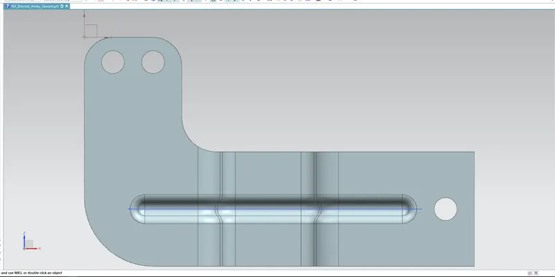
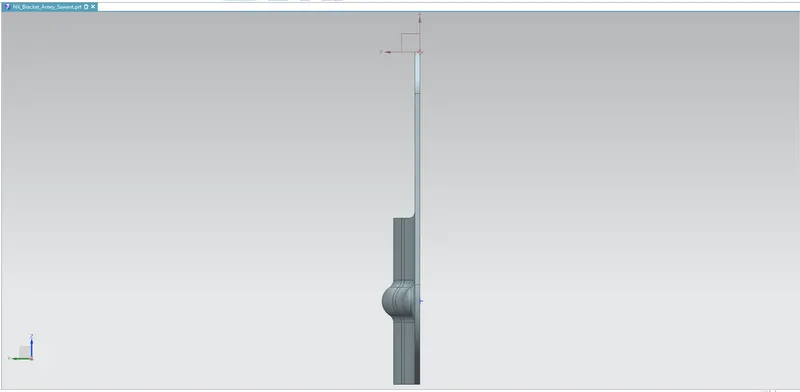
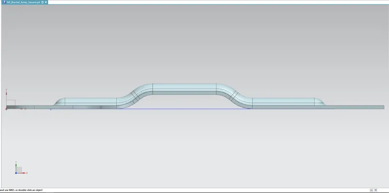
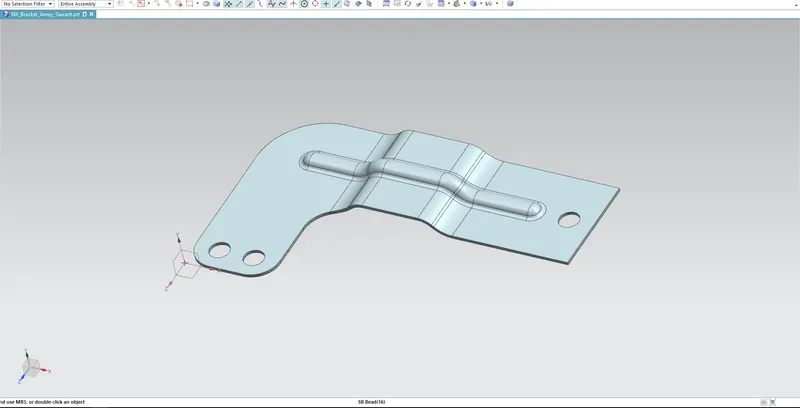
Below are the images of Odd Shaped Enclosure
FRONT VIEW
SIDE VIEW
TOP VIEW
ISOMETRIC VIEW
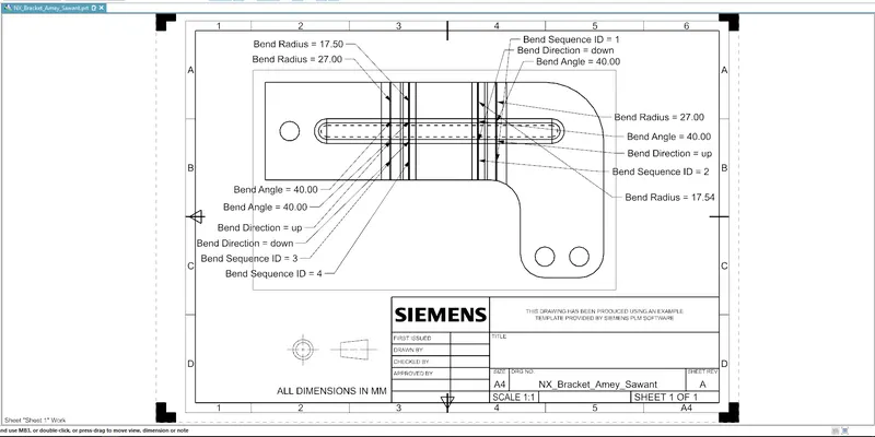
Detailed Drawing Sheet
Conclusion:
- This report conclude that the “Bracket” is created by using various tools/features mentioned above by using the NX CAD software.
- And a detailed drawing sheet has been attached in the report as well.