Photo Realistic Rendering
3D MODELING AND RENDERING OF AMERICAN CHOPPER(MOTORCYCLE) USING SOLIDWORKS
OBJECTIVE: -
The main objectives of this projects are
- To create various essential parts of an American chopper with the help of Solidworks.
- To assemble created parts in assembly workbench in Solidworks.
- Creating 3d rendered images of assembly of the chopper with the help of Photo View 360 and Solidworks visualize.
INTRODUCTION: -
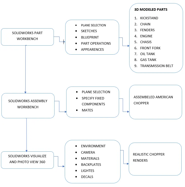
Solidworks is a computer-aided design and computer-aided engineering software developed by Dassault Systems.it is mainly used for solid modeling of products and components and it is widely using CAD software across the world. The software contains various add-ins feature for various purposes for instance photo view 360, CircuitWorks, Solidworks simulation, Solidworks Motion, etc. In this particular project, we will be using Solidworks Part Workbench, assembly Workbench, Photoview 360, and Solidworks Visualize. The Solidworks part workbench is used for creating different components individually of chopper while assembly Workbench is used for assembling those parts to form the chopper, on the other hand, Photoview 360 and Solidworks Visualize are used for setting up the realistic environment, lights, shadows, giving appropriate appearances to parts and creating 3d rendered images.
DESIGN METHODOLOGY/FLOW CHART: -
DESCRIPTION (TOOLS AND FEATURES): -
1.KICKSTAND: - It is a component used to lay down the chopper on a very slight angle and is also known as a side stand.
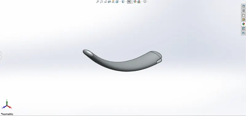
FEATURE AND TOOLS USED IN KICKSTAND:-
- Sketches
- loft
- Dome
- Cut extrude
- split
- boss extrude
- fillets
1.Sketch: - Sketch is a 2-dimensional entity that describes the shape of an object when we see it from the right angle. Line, circle, arc, spline, etc. are the constituent of a sketch.
2.loft:- loft is a feature used to create the shape of the kickstand with the help of three independent sketches. among the three sketches, two sketches define the cross-section of the kickstand while the third sketch gives curvature to the kickstand.
3.Dome:- dome feature gives a half-sphere/elliptical shape to a planer or a nonplanar surface.
4.Cut extrude:- this feature is used to remove material from 3d cad model. it is also based on a sketch profile which we want to remove from our model and it is opposite from extruding boss feature where we add material based on our sketched profiles.
5.split:- split tool is used to convert a 3d model into two halves based on the profile we selected we can either keep split entity or simply remove them by consuming the cut bodies option.
6.boss extrude:-this tool is used to create the desired shape based on our sketched profiles this tool provides various options to create the parametric design of our model.
7.Fillets:-this feature is used to create rounded corners in our cad models we can select an edge or two faces to create the fillet.it also makes our model look more realistic and provides a better perspective.
2.TRANSMISSION BELT:- Transmission belt is used to transfer the engine power to the gearbox.
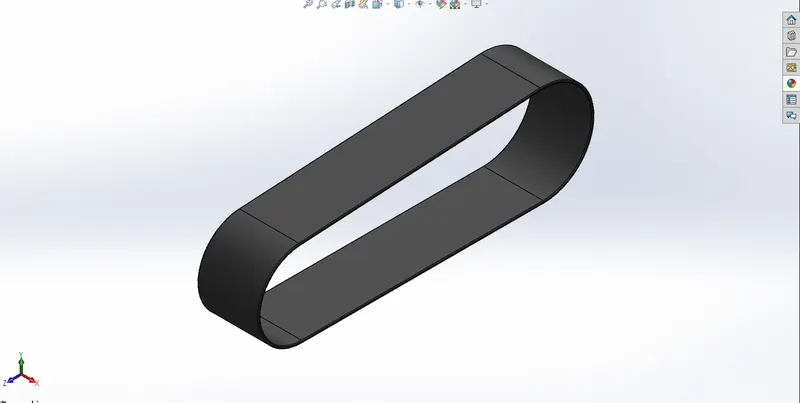
Features and tools used to create transmission belt:-
- sketch
- offset sketch entities
- boss extrude
Offset sketch entities:- this feature is used to create an existing sketch or its entity to a distance both inward and outward.
3.FRONT FENDER:- front fender is a component used to protect both rider and chopper from dust and mud.
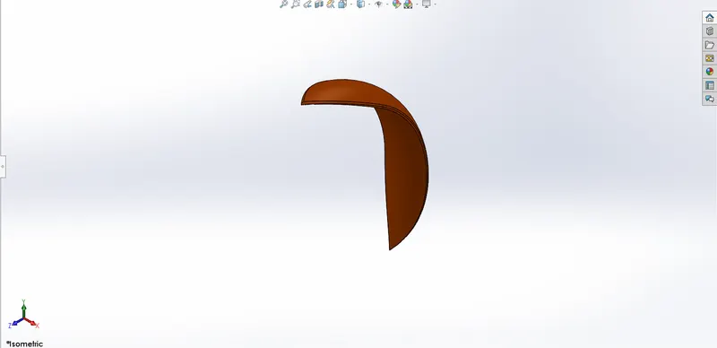
Feature and tools used to create front fender:-
- Sketch
- axis
- revolve
- split
- fillets
Axis:- we can create an axis based on our plane selection.
Revolve:- this feature enables us to create objects just by their cross-section and an axis about which our profile revolves. we can give the desired angle to create an object.
4.REAR FENDER:-rear fender gives a shield against dirt, mud, and soil particles to chopper and rider.
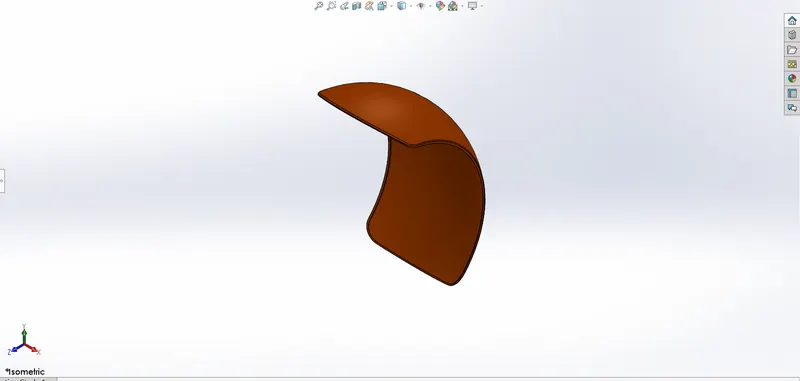
Feature and tools used to create rear fender:-
- Sketch
- axis
- revolve
- split
- fillets
5.chain:-chain is a part of the transmission system of our chopper and it is used to transmit engine power to the wheel from the gearbox and it is consists of the inner link and outer link.
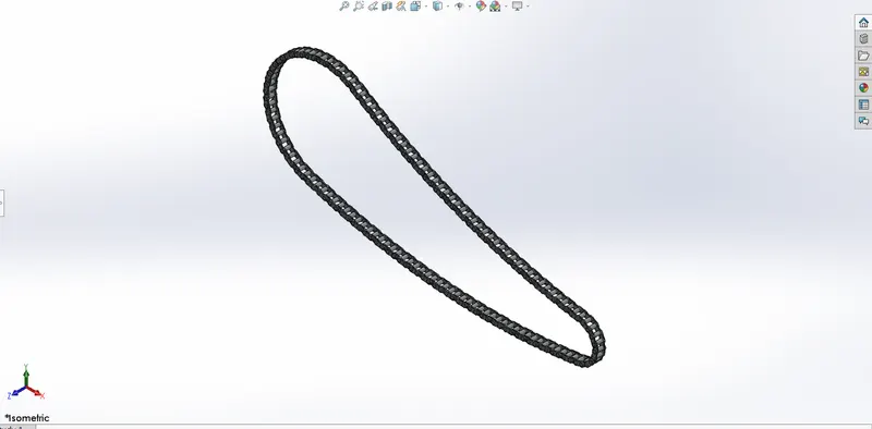
Feature and tools used to create chain:-
- sketch
- trim entities
- blocks
- fillets
- curve driven pattern
- boss extrude
- mirror
Trim entities:- this tool is used under the sketch workbench where we can get rid of unnecessary sketch entities by some of the trim options for instance power trim, corner, etc.
Blocks:-this Solidworks feature is very useful when it comes to using a particular entity frequently this feature allows us to save a particular set of the item as a block and when we need them into our sketch we can simply insert them by insert block option.
Curve-driven pattern:- this Solidworks feature is very handy when we want to arrange our cad models or blocks to a defined path.
Mirror:- the mirror feature comes into action when we want to create a copy version or symmetric version of our model we can create the same by defining a mirror plane or line.
6.Oil tank:-it is a closed enclosure of metal surrounding, which is used to store fuel required for the engine to operate.it has a thickness of less than 4mm.
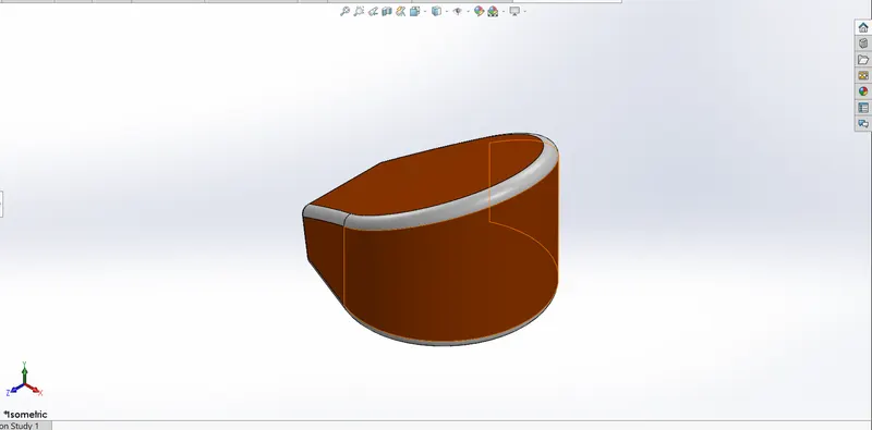
Feature and tools used to create chain:-
- sketch
- boss extrude
- combine
- fillets
- shell
Combine:- combine feature is used to make one single body with the help of 2 or more bodies combine feature gives us various options to obtain the desired shape of the body for instances common, subtract and add.
Shell:- shell feature is used to giving thickness to our 3d cad model for example we have given 3mm thickness to the fuel tank with the help of the shell feature.
7.Pedal:- pedal is attached to the chassis and its function is to give space to the rider for a footrest.
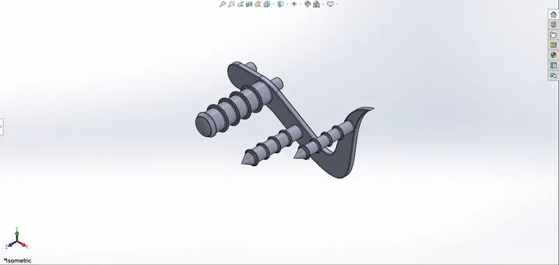
Feature and tools used to create Pedal:-
- sketch
- boss extrude
- fillets
- revolve
- dome
- chamfer
- linear pattern
Chamfer:- chamfer feature gives us a slope to an edge or corner to give a soft curve rather than a sharp edge. chamfer feature gives us options that help us to create the desired shape of edge or corner for instance distance-distance, angle-distance, etc.
Linear pattern:-linear pattern is used to create several existing sketched entities or parts toward the specified direction.
8.FRONT WHEEL:- generally a chopper wheel is made up of a rotor, tire, rim, and caliper.
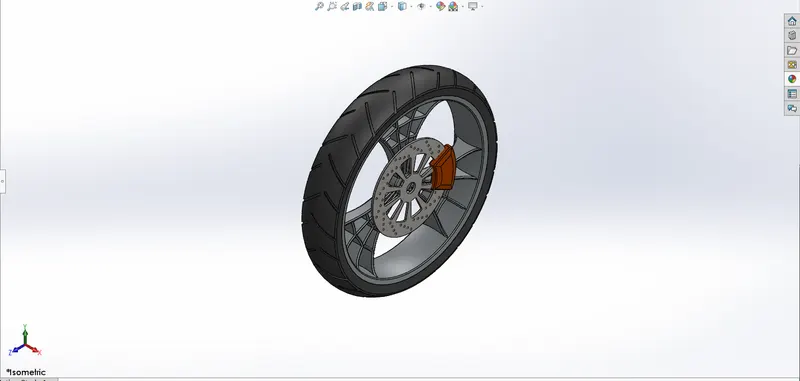
Feature and tools used to create Front wheel:-
- Revolve
- boss extrude
- cut revolve
- cut revolve
- circular pattern
- combine
- fillet
- chamfer
Cut Revolve:-this feature removes material from a cad model based on sketched profile.
Circular pattern:- this feature used to create identical objects on the prescribed degree of rotation
9.REAR WHEEL:-generally, a chopper wheel is made up of a rotor, tire, rim, and caliper.
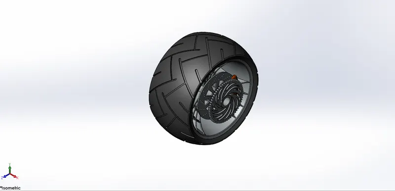
Feature and tools used to create Rear wheel:-
- Revolve
- boss extrude
- cut revolve
- cut revolve
- circular pattern
- combine
- fillet
- chamfer
10.FRONT FORK:-front fork of the chopper is made up of a shock absorber, axle, headlamp and gives direction to the chopper.
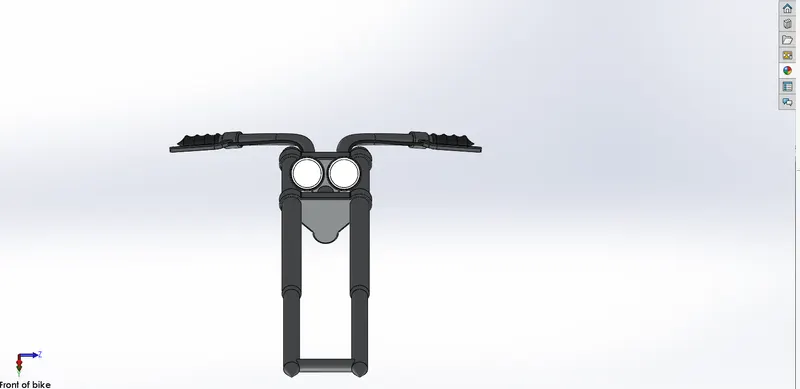
Feature and tools used to create Rear wheel:-
- Sketch
- Revolve
- Boss extrude
- Fillet
- Linear pattern
- Cut extrude
- Cut Revolve
- Body move copy
- Sweep
- Combine
- Mirror
- projected curve
Body move copy:-This feature is used to interpolate a body along the 3-dimensional axis.
Sweep:-sweep feature is used to make complex geometry with the help of a pierce relationship between profile and guide curve.
projected curve:- project curve is a 3d curve that is created by two different 2-dimensional sketches.
11.CHASSIS:-Chassis is the skeleton of a chopper with all major parts attached to it.
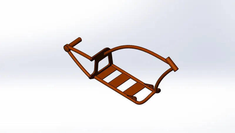
Feature and tools used to create Chassis:-
- sketch picture
- sketch
- projected curve
- sweep
- mirror
- boss extrude
- cut extrude
- chamfer
- fillet
- plane
- split
- combine
- dome
Sketch picture:- sketch picture works as a reference to create 3d model. we can attach the reference picture to our model and resize it according to our desired dimension.
Plane:-we can create a plane in our cad model to create 3d entities on any angle and direction.
12.ENGINE:-Engine is the source of energy that is necessary to propel the chopper. an engine converts the chemical energy of fuel into heat energy which is then converted into mechanical energy.
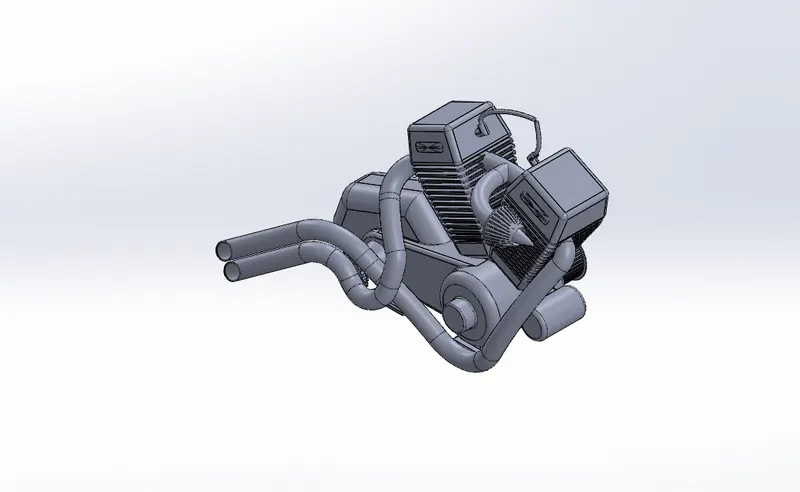
Feature and tools used to create Chassis:-
- Sketch
- Boss extrude
- fillet
- revolve
- plane
- circular pattern
- Dome
- cut extrude
- chamfer
- Linear pattern
- Mirror
- Sweep
- Combine
- Projected curve
- Composite curve
- split
Composite curve:-composite curve feature allows us to add two individual curves into one single curve.
13.GAS TANK:- gas tank provides a facility to store gas and give aesthetics to the chopper.
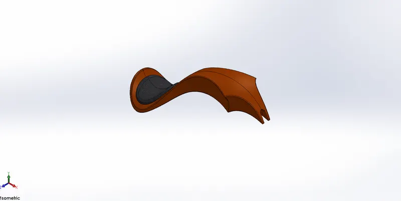
Feature and tools used to create Gas tank:-
- Sketch
- plane
- Surface-sweep
- Surface-trim
- projected curve
- Surface-loft
- Boundary
- mirror
- Surface knit
- Surface Extrude
- Fillets
- Cut sweep
- Shell
Surface Seep:-this feature allows us to create a surface through the profile and a guide curve.
Surface trim:-this feature allows us to remove the surface with the help of a projected sketch profile.
Surface loft:-this feature creates a surface with the help of surface edge or profiles and guide curves.
Boundary:-boundary feature allows us to create a surface with the help of 2 different direction-based sketched profiles and curves.
Surface knit:-this surface-based feature allows the creation of one single surface by joining two or more surfaces.
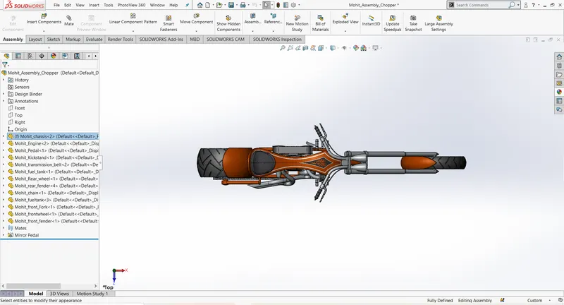
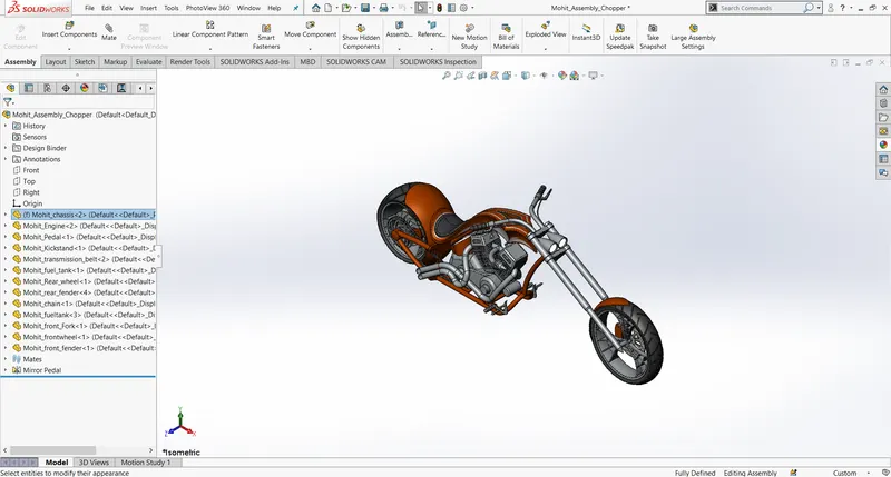
ASSEMBLY OF THE CHOPPER:- This assembly workbench allows us to assemble all parts of the chopper utilizing mates. our first step is to fix the chassis to the main coordinate system of the assembly workbench this allows us to a reference to attach other parts of the chopper.
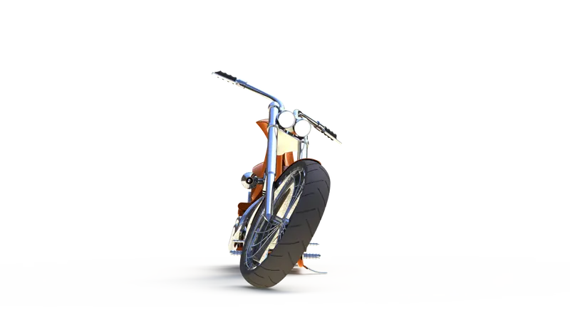
FRONT VIEW OF ASSEMBLED CHOPPER:-
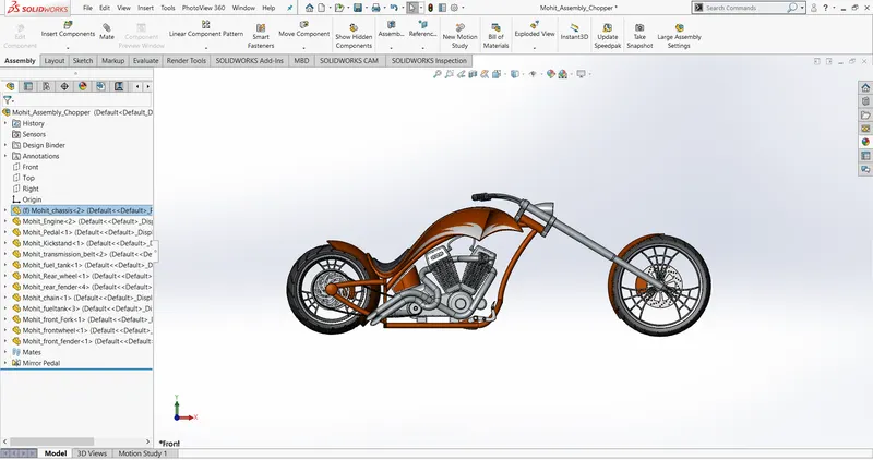
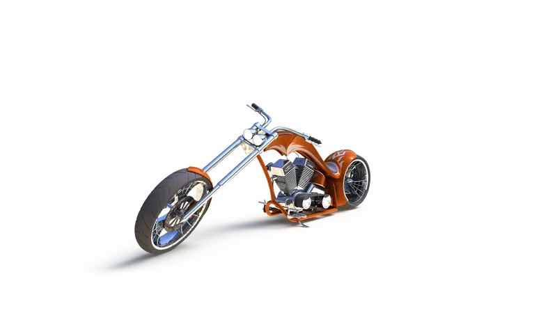
SIDE VIEW OF ASSEMBLED CHOPPER
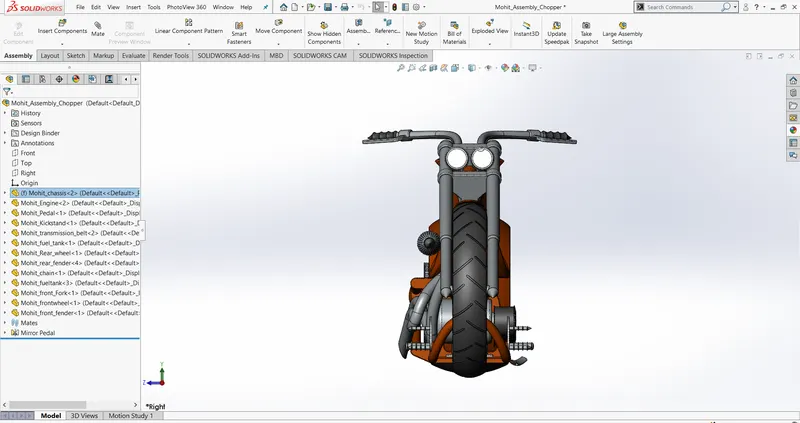
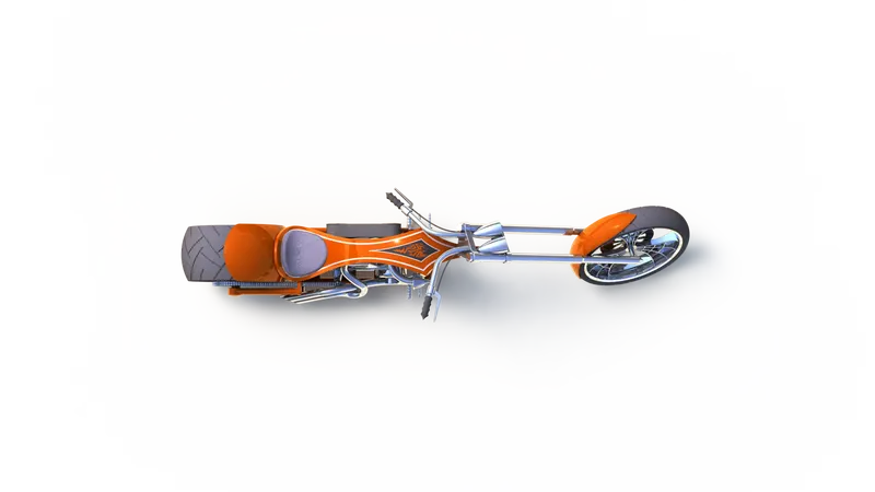
TOP VIEW OF ASSEMBLED CHOPPER:-
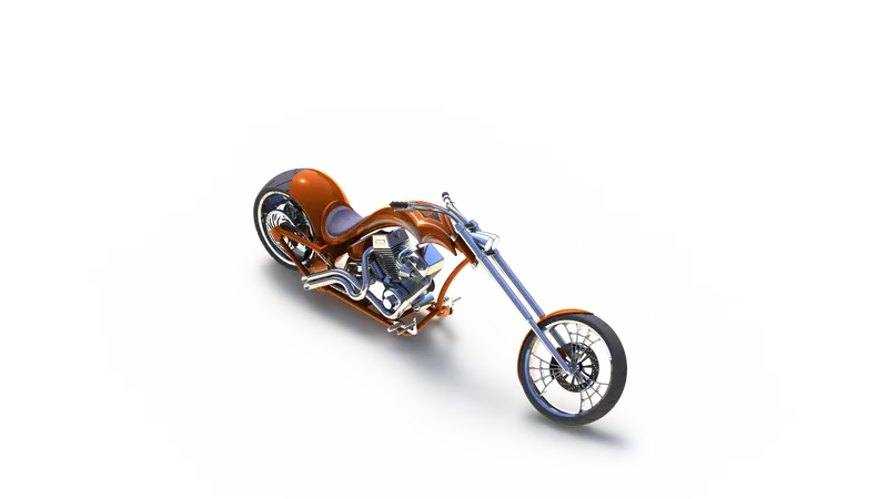
ISOMETRIC VIEW OF ASSEMBLED CHOPPER:-
Features to create an assembly of the chopper:-
- Mates
- inserting the parts
Inserting the parts:-This is our first step inside the assembly workbench we can browse entire created parts and bring them into our assembly.
Mates:-mates defines the relationship between two or parts that are connected. in chopper assembly, we have used various kinds of mates for instance Coincident, parallel, perpendicular, tangent, concentric, limit angle, and some advanced mates such as width mate.
RENDERING OF CHOPPER:-
Firstly, we have adjusted the position of the chopper in the assembly workbench it has allowed us to have a realistic look at the chopper. We have used two different methods for rendering the chopper first is via PHOTO VIEW 360 and the other is SOLIDWORKS VISUALIZE.
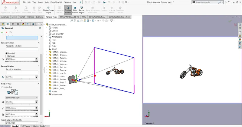
PHOTO VIEW 360:-It is an add-ins feature of Solidworks for rendering, setting up the environment, camera, lights, and decals. We can give different appearances to our parts with a variety of choices.
firstly we have set up the Scene by choosing the appropriate environment and background then we created a camera and set its setting according to our preferences then we have applied decals to the gas tank, rear fender, and fuel tank.
with the help of the options tool in photo view 360, we can adjust the output image size, formate, render quality, and other caustic settings.
Camera setup view:-
Frontview render:-
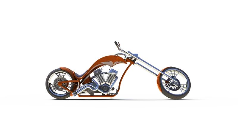
Sideview render:-
Cameraview render:-
topview view render:-
Isometric view render:-
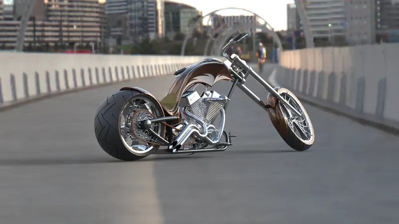
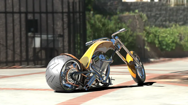
SOLIDWORKS VISUALIZE:-Solidwork visualize is an additional tool to render our model it gives all facilities the same as photo view 360.
CONCLUSION:-In this project we have learned the following :
- 3d modeling of chopper parts with the help of Solidwork part workbench.
- assembling of parts through the Assembly workbench.
- rendering of the chopper and setting up lights, environment, decals, appearances, and camera.