Modelling of the American chopper
Modelling of the American chopper in Solid-works
Introduction:
Solid-works is an engineer software used to create real models of mechanical part and from these models the technical drawings that will be used to manufactory the parts modelled.
It can also be used to apply appearances, materials and perform analyses such as FEA and CFD.
In this curse model will be learning how to create each component of an American chopper and also how to assembly it.
Design methodology/approach:
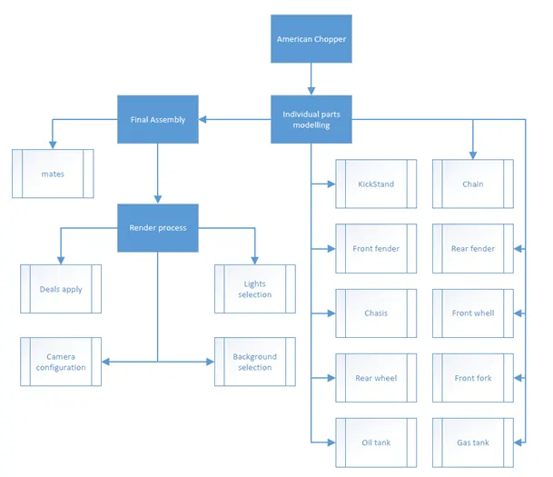
Objectives:
The objective of this model is to learn all the features necessary to create each of the component of an American chopper and also how to assembly it. Will be also learning how to use the photo view 360 and visualize to render the final assembled model.
Description of each component modelled.
Chain: It is the transition element of the chopper which bring movement to the rear wheel
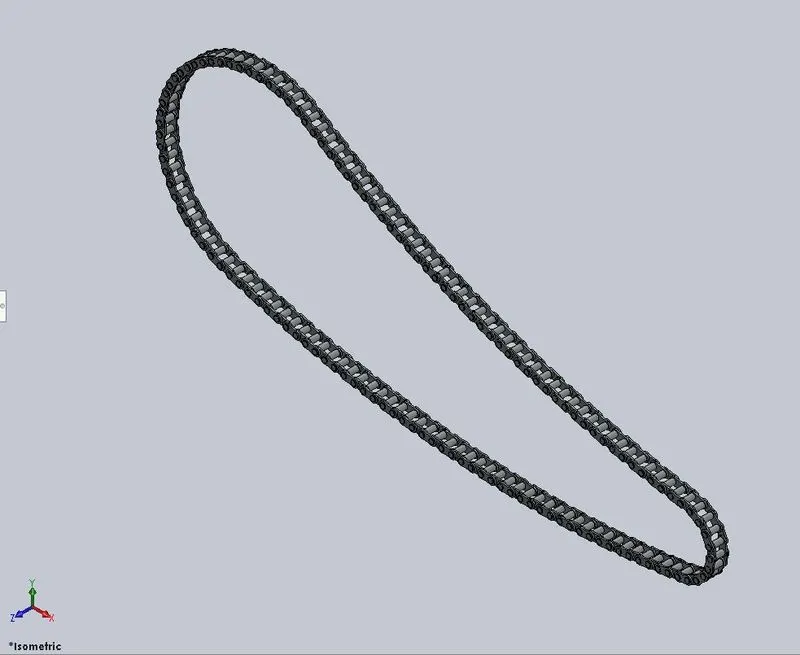
Features used to model the part & description:
Sketch: Is a 2D drawing representation that can used to create the 3D solid model and/or modify an existing 3d solid model. Inside the sketch you can use different tools to create it and they are known as sketch entities.
Appearances: Is where you can apply materials, colours, textures and appearances to your 3D model.
Boss Extrude: Is uses to create a solid 3D model from a sketch.
Fillet: Is used to create internal/external rounded edges.
Circular pattern: Is used to create multiple copies of an existing body following a circular pattern.
Mirror: Is used to create a mirrored body of an existing one.
Blocks: Is used to save a sketch that may need to be used multiple times on the model. In this way you bring this sketch to the project whenever is needed and ensure that all of them will be always the same
Chassis: It is the structure of the chopper where all the other parts will be mounted on.
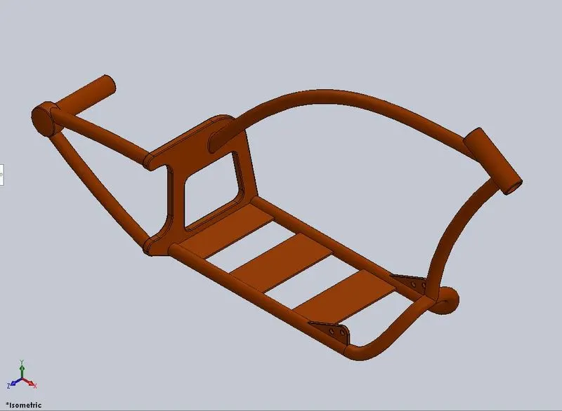
Features used to model the part & description:
Sketch: Is a 2D drawing representation that can used to create the 3D solid model and/or modify an existing 3d solid model. Inside the sketch you can use different tools to create it and they are known as sketch entities.
Appearances: Is where you can apply materials, colours, textures and appearances to your 3D model.
Sketch Picture: Is used to bring into solid works an external image that can be used as reference to create sketches.
Projected Curve: Is a 3D curve that is generated by the junction of 2 or more 2D curves.
Sweep: Is used to generate a solid body by sweeping a 2D sketch (profile) along a another sketch (path)
Mirror: Is used to create a mirrored body of an existing one.
Boss Extrude: Is uses to create a solid 3D model from a sketch.
Cut Extrude: Is used to cut an existing 3D solid model from a sketch.
Chamfer: Is used to brake/cut edges.
Fillet: Is used to create internal/external rounded edges.
Reference Plane: Is used to create alternative planes that are need to generate sketches and geometry.
Dome: Is used to create domes on flat surfaces.
Split Tool: Is used to project an entity sketch to a solid model and slip it. You are also be able to define with of the split bodies will remain.
Combine: Is used to combine 2 or more solid bodies in only one.
Revolve: Is used to generate a solid 3D model by revolving a sketch (profile) along another sketch (path)
Engine: It is source of power of chopper from where the energy to move the rear wheel will be generated.
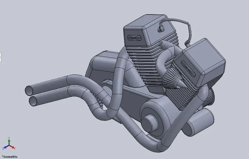
Features used to model the part & description:
Sketch: Is a 2D drawing representation that can used to create the 3D solid model and/or modify an existing 3d solid model. Inside the sketch you can use different tools to create it and they are known as sketch entities.
Appearances: Is where you can apply materials, colours, textures and appearances to your 3D model.
Sketch Picture: Is used to bring into solid works an external image that can be used as reference to create sketches.
Boss Extrude: Is uses to create a solid 3D model from a sketch.
Fillet: Is used to create internal/external rounded edges.
Revolve: Is used to generate a solid 3D model by revolving a sketch (profile) along another sketch (path)
Reference Plane: Is used to create alternative planes that are need to generate sketches and geometry.
Circular Pattern: Is used to create multiple copies of an existing body following a circular pattern.
Linear Patter: Is used to create multiple copies of an existing body following a linear pattern
Dome: Is used to create domes on flat surfaces.
Cut Extrude: Is used to cut an existing 3D solid model from a sketch.
Chamfer: Is used to brake/cut edges.
Mirror: Is used to create a mirrored body of an existing one.
Split Tool: Is used to project an entity sketch to a solid model and slip it. You are also be able to define with of the split bodies will remain.
Sweep: Is used to generate a solid body by sweeping a 2D sketch (profile) along a another sketch (path)
Projected Curve: Is a 3D curve that is generated by the junction of 2 or more 2D curves.
Composite Curve: Is used to joint 2 individual curves.
Front Fender: Is the part that will cover the front wheel
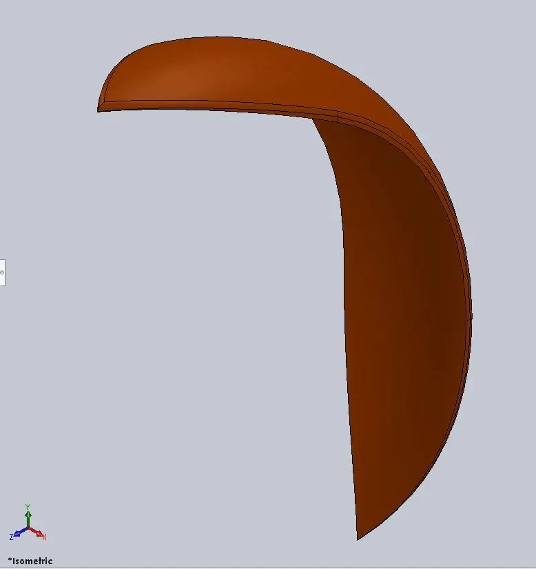
Features used to model the part & description:
Sketch: Is a 2D drawing representation that can used to create the 3D solid model and/or modify an existing 3d solid model. Inside the sketch you can use different tools to create it and they are known as sketch entities
Appearances: Is where you can apply materials, colours, textures and appearances to your 3D model
Revolve: Is used to generate a solid 3D model by revolving a sketch (profile) along another sketch (path)
Split Tool: Is used to project an entity sketch to a solid model and slip it. You are also be able to define with of the split bodies will remain.
Fillet: Is used to create internal/external rounded edges.
Rear Fender: Is the part that will cover the rear wheel
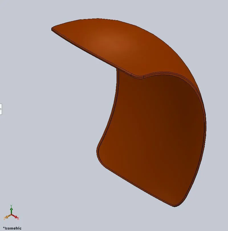
Features used to model the part & description:
Sketch: Is a 2D drawing representation that can used to create the 3D solid model and/or modify an existing 3d solid model. Inside the sketch you can use different tools to create it and they are known as sketch entities.
Appearances: Is where you can apply materials, colours, textures and appearances to your 3D model.
Revolve: Is used to generate a solid 3D model by revolving a sketch (profile) along another sketch (path)
Split Tool: Is used to project an entity sketch to a solid model and slip it. You are also be able to define with of the split bodies will remain.
Fillet: Is used to create internal/external rounded edges.
Shell: Is used to create a shell internally to a solid body or to a surface. You can also define how thick it will be.
Front Fork: Is the part where we will have the steering wheel and also the front wheel along with the lights
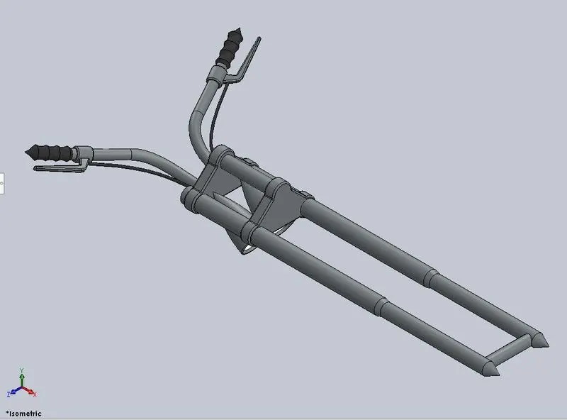
Features used to model the part & description:
Sketch: Is a 2D drawing representation that can used to create the 3D solid model and/or modify an existing 3d solid model. Inside the sketch you can use different tools to create it and they are known as sketch entities.
Appearances: Is where you can apply materials, colours, textures and appearances to your 3D model.
Revolve: Is used to generate a solid 3D model by revolving a sketch (profile) along another sketch (path)
Boss Extrude: Is uses to create a solid 3D model from a sketch.
Fillet: Is used to create internal/external rounded edges.
Linear Pattern: Is used to create multiple copies of an existing body following a linear pattern
Cut Extrude: Is used to cut an existing 3D solid model from a sketch.
Dome: Is used to create domes on flat surfaces.
Cut Revolve: Is used to cut an existing solid body with a sketch following a circular path.
Body-Move/Copy: Is used to copy or move an existing body from one place to other.
Projected Curve: Is a 3D curve that is generated by the junction of 2 or more 2D curves.
Sweep: Is used to generate a solid body by sweeping a 2D sketch (profile) along a another sketch (path)
Reference Plane: Is used to create alternative planes that are need to generate sketches and geometry.
Mirror: Is used to create a mirrored body of an existing one.
Combine: Is used to combine 2 or more solid bodies in only one.
Front Wheel:
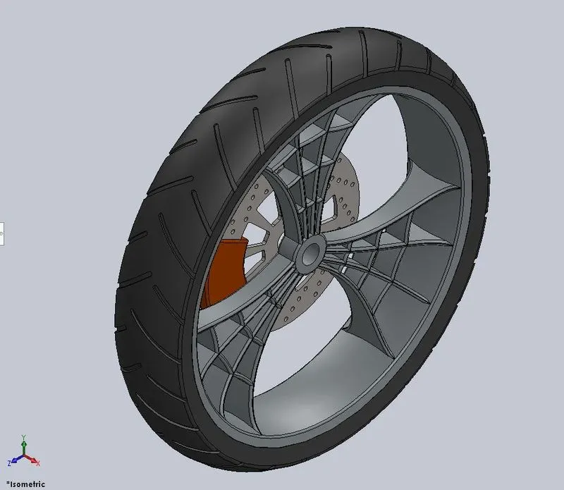
Features used to model the part & description:
Sketch: Is a 2D drawing representation that can used to create the 3D solid model and/or modify an existing 3d solid model. Inside the sketch you can use different tools to create it and they are known as sketch entities.
Appearances: Is where you can apply materials, colours, textures and appearances to your 3D model.
Revolve: Is used to generate a solid 3D model by revolving a sketch (profile) along another sketch (path)
Boss Extrude: Is uses to create a solid 3D model from a sketch.
Cut Extrude: Is used to cut an existing 3D solid model from a sketch.
Cut Revolve: Is used to cut an existing solid body with a sketch following a circular path.
Circular Pattern: Is used to create multiple copies of an existing body following a circular pattern.
Combine: Is used to combine 2 or more solid bodies in only one.
Fillet: Is used to create internal/external rounded edges.
Chamfer: Is used to brake/cut edges.
Rear Wheel:
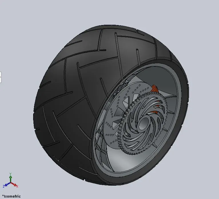
Features used to model the part & description:
Sketch: Is a 2D drawing representation that can used to create the 3D solid model and/or modify an existing 3d solid model. Inside the sketch you can use different tools to create it and they are known as sketch entities.
Appearances: Is where you can apply materials, colours, textures and appearances to your 3D model.
Revolve: Is used to generate a solid 3D model by revolving a sketch (profile) along another sketch (path)
Boss Extrude: Is uses to create a solid 3D model from a sketch.
Cut Extrude: Is used to cut an existing 3D solid model from a sketch.
Circular Pattern: Is used to create multiple copies of an existing body following a circular pattern.
Combine: Is used to combine 2 or more solid bodies in only one.
Cut Revolve: Is used to cut an existing solid body with a sketch following a circular path.
Fillet: Is used to create internal/external rounded edges.
Chamfer: Is used to brake/cut edges.
Gas tank: Is where the gas will be storage on the chopper.
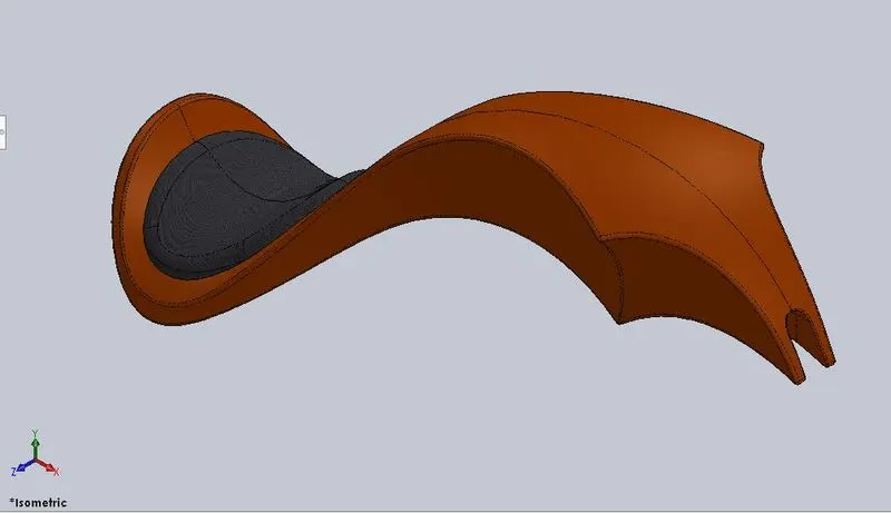
Features used to model the part & description:
Sketch: Is a 2D drawing representation that can used to create the 3D solid model and/or modify an existing 3d solid model. Inside the sketch you can use different tools to create it and they are known as sketch entities.
Appearances: Is where you can apply materials, colours, textures and appearances to your 3D model.
Reference Plane: Is used to create alternative planes that are need to generate sketches and geometry.
Surface Sweep: is used to generate a surface from a curve projected along a path.
Surface Trim: Is used to cut material from an existing surface.
Projected Curve: Is a 3D curve that is generated by the junction of 2 or more 2D curves.
Surface Loft: Is used to create surfaces from multiple 3D curves.
Boundary Surface: Is used to create surfaces between profiles.
Mirror: Is used to create a mirrored body of an existing one.
Surface Knit: Is used to knit two edges of a surface together.
Split: Is used to project an entity sketch to a solid model and slip it. You are also be able to define with of the split bodies will remain
Surface Extrude: Is used to extrude a sketch and create a surface from it.
Fillet: Is used to create internal/external rounded edges.
Cut Sweep: Is used to cut an existing solid model by sweeping a sketch (profile) along another sketch (path)
Shell: Is used to create a shell internally to a solid body or to a surface. You can also define how thick it will be.
Kick Stand: Is used to support the chopper stand while parked.
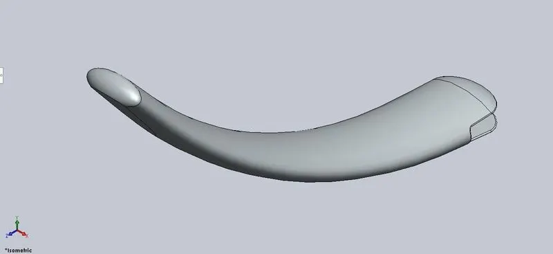
Features used to model the part & description:
Sketch: Is a 2D drawing representation that can used to create the 3D solid model and/or modify an existing 3d solid model. Inside the sketch you can use different tools to create it and they are known as sketch entities.
Appearances: Is where you can apply materials, colours, textures and appearances to your 3D model.
Reference Plane: Is used to create alternative planes that are need to generate sketches and geometry.
Loft: Is used to create a solid model by joining two sketches trough a path.
Dome: Is used to create domes on flat surfaces.
Cut Extrude: Is used to cut an existing 3D solid model from a sketch.
Split Tool: Is used to project an entity sketch to a solid model and slip it. You are also be able to define with of the split bodies will remain.
Boss Extrude: Is uses to create a solid 3D model from a sketch.
Oil Tank: Is where eth oil for the engine will be storage.
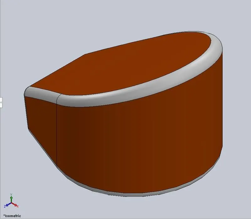
Features used to model the part & description:
Sketch: Is a 2D drawing representation that can used to create the 3D solid model and/or modify an existing 3d solid model. Inside the sketch you can use different tools to create it and they are known as sketch entities.
Appearances: Is where you can apply materials, colours, textures and appearances to your 3D model.
Boss Extrude: Is uses to create a solid 3D model from a sketch.
Combine: Is used to combine 2 or more solid bodies in only one.
Fillet: Is used to create internal/external rounded edges.
Shell: Is used to create a shell internally to a solid body or to a surface. You can also define how thick it will be.
Pedal: Is where you can control the cloth of the chopper and also the rear brakes.
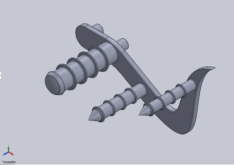
Features used to model the part & description:
Sketch: Is a 2D drawing representation that can used to create the 3D solid model and/or modify an existing 3d solid model. Inside the sketch you can use different tools to create it and they are known as sketch entities.
Appearances: Is where you can apply materials, colours, textures and appearances to your 3D model.
Boss Extrude: Is uses to create a solid 3D model from a sketch.
Fillet: Is used to create internal/external rounded edges.
Revolve: Is used to generate a solid 3D model by revolving a sketch (profile) along another sketch (path)
Dome: Is used to create domes on flat surfaces.
Chamfer: Is used to brake/cut edges.
Linear Pattern: Is used to create multiple copies of an existing body following a linear pattern
Transmission Belt: This element is responsible to transmit the power from the motor to the gearbox where the selected velocity will be transmitted to the rear wheel
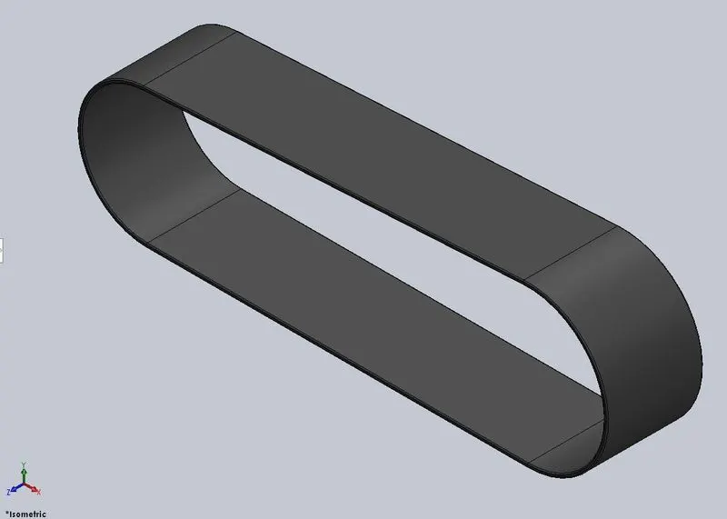
Features used to model the part & description:
Sketch: Is a 2D drawing representation that can used to create the 3D solid model and/or modify an existing 3d solid model. Inside the sketch you can use different tools to create it and they are known as sketch entities.
Appearances: Is where you can apply materials, colours, textures and appearances to your 3D model.
Boss Extrude: Is uses to create a solid 3D model from a sketch.
Fillet: Is used to create internal/external rounded edges.
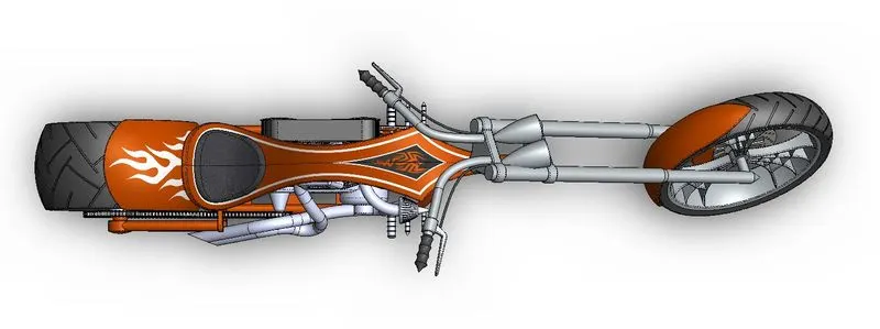
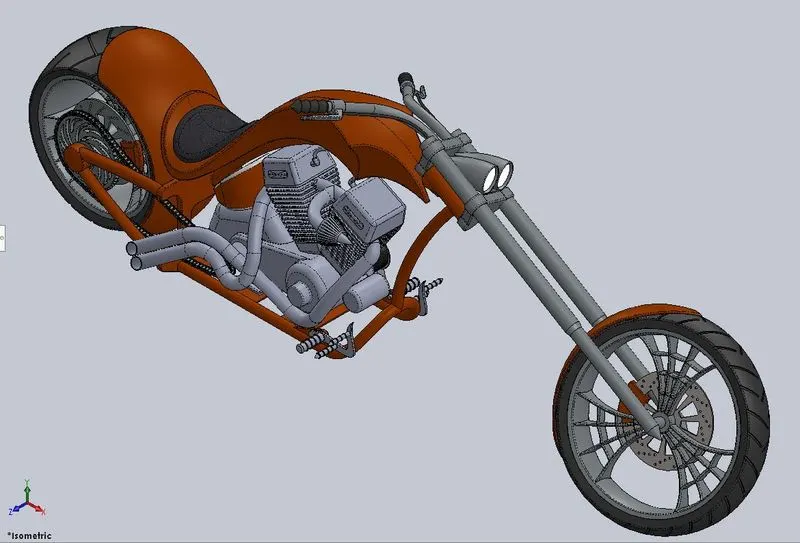
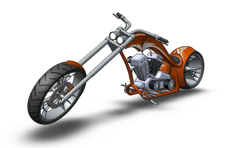
Chopper Assembly:
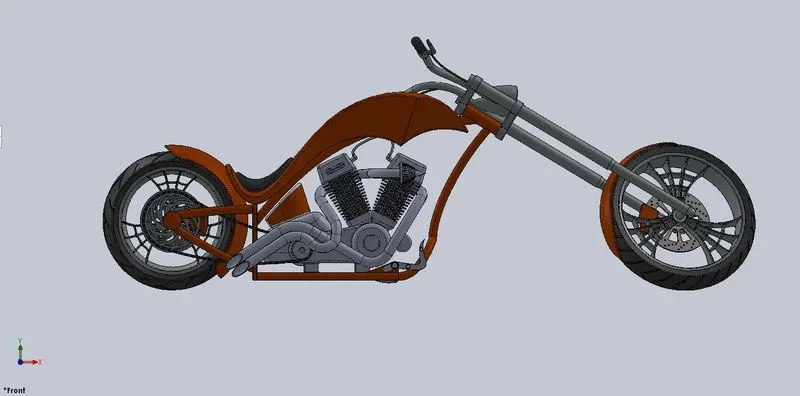
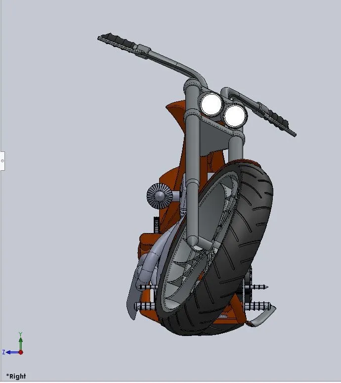
Features used to model the part & description:
Mates: Are used to define geometric relationships between the parts of the assembly.
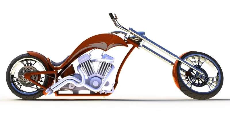
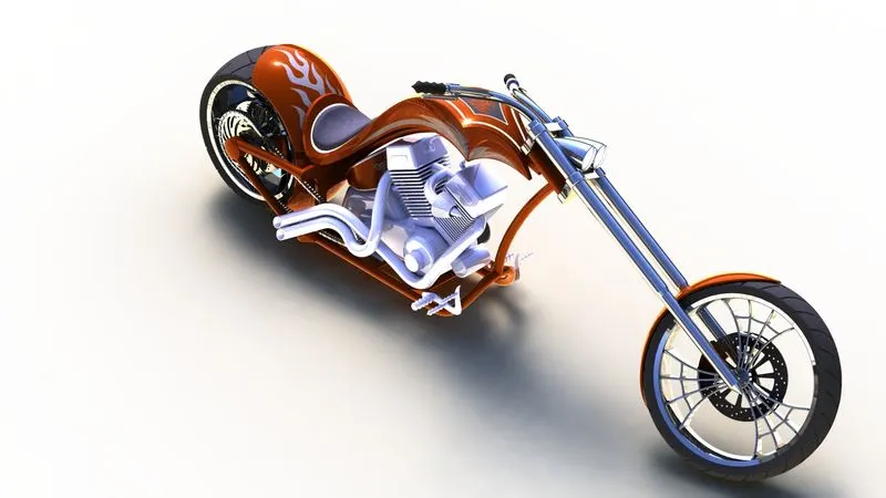
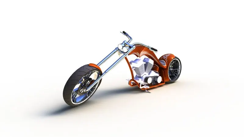
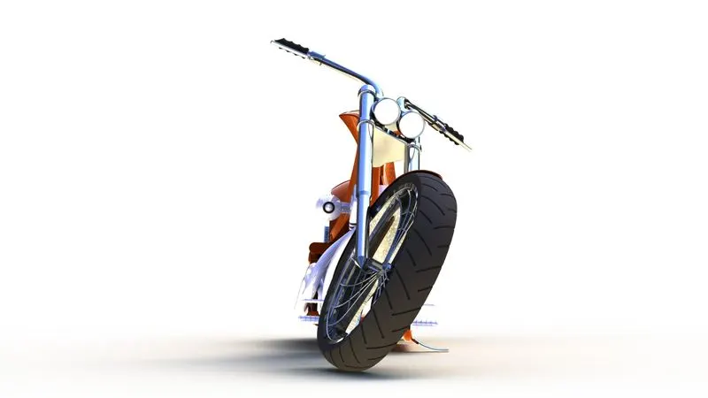
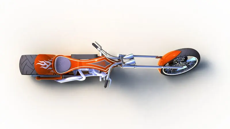
Rendering: It is the process of creating a real image of the model created by applying material, appearances, cameras, light and backgrounds.
Conclusion:
All parts of the American shopper are modelled as per the instruction along with the final assembled model.
The final model is rendered showing a very real image of how this chopper should look on a real scenario.