Advanced Sheet Metal Design Using NX Cad Challenge_6_Bracket
Modelling of the bracket in NX Simmens
Introduction:
Simmens NX is an engineer software used to create real models of mechanical part and from these models the technical drawings that will be used to manufactory the parts modelled.
Design methodology
Objectives:
The objective of this this module is to learn all the features necessary to create a bracket.
Description of the modelling process.
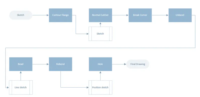
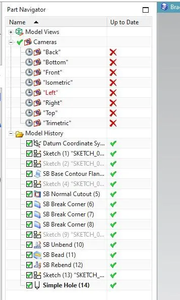
Sketch: Is used to draw any kid of shape in a 2D space that will be used to generate a solid model.
Unbend: Is used to unbend the existing sheet metal so you can apply extra features to it looking at the part on the pre-ending stage.
Simple screw hole: Is used to add holes to the existing sheet metal.
Bead: In the same why of the dimple this feature will lift or lower the material from a sketch simulating a stamp tool.
Re-bend: Is used to re-bend the metal sheet to it final stage which was predefined before we start adding the details such as dimples and beads.
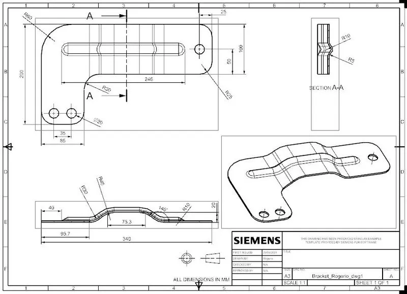
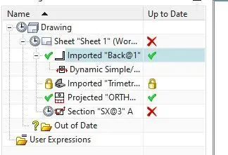
Drawing/Drafting: Is used to create a drawing of the part modelled where you can define one or more views to be added.
Contour Flange: Is Used to create a sheet metal already with a flange from a 2D sketch.
Breack corners: Is used to eliminate sharp edges on the existing part, it can be either chamfers or fillets.
Normal cut-out: Is used to create a cut-out on the solid model. This feature needs also a sketch that will drive the shape of the cut-out.
Conclusion:
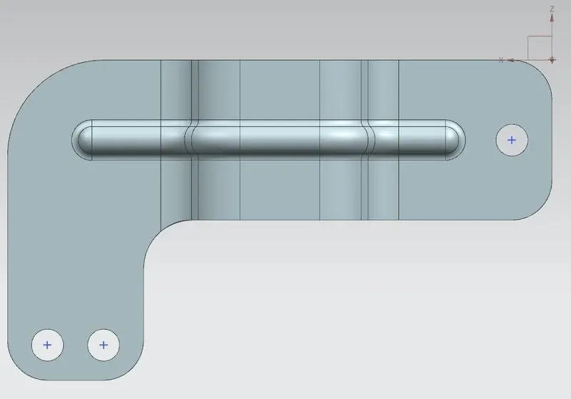
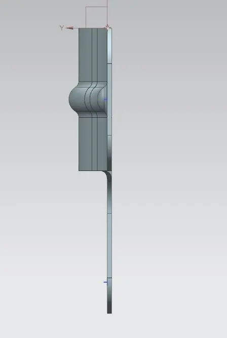
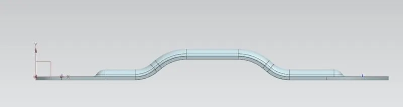
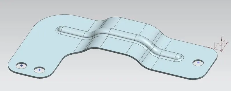
The final bracket sheet metal along with the detailed final drawing were completed using the above features.