American Chopper assembly and rendering using Solidworks
Aim:
- To model all the parts of American Chopper using Solidworks.
- To assemble all the parts of American Chopper.
- To create a photo-realistic view of American Chopper using Solidworks PhotoView360 and Solidworks Visualise.
Theory:
Features used to model the parts:
- Sketch entities: The tools which are used to draw a model in 2D are known as Sketch entities. Line, arc,
spline, rectangle, circle, ellipse, slot etc., are known as sketch entities. These are profiles for models. These are drawn on a plane/view. - Sketch tools: These are used to edit the profiles sketch entities are per requirements. Trim entities, Extend entities, linear patterns, circular patterns, offset entities, move entities etc., are known as Sketch tools.
- Extrude Boss/Base: The profile sketch forcing out to form a 3d model known as Extrude. This can be solid or with a certain thickness. The profile is forced only perpendicular to the plane.
- Swept Boss/Base: The sketch is passed through the curve to form a 3D model in a certain path.
- Revolve Boss/Base: The profile sketch is converted into the model by rotating in certain degrees w.r.t mentioned axis.
- Loft Boss/Base: Multiple profiles are used to create certain 3D shapes where multiple profiles are available at different planes.
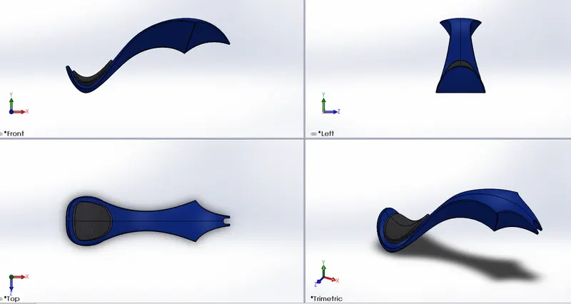
- Extrude Cut: The profile is used to cut the modelled material perpendicular to the plane.
- Swept cut: The profile removes the material of a given curve.
- Revolve cut: The profile removes the material to certain degrees.
- Loft cut: The profile removes the material at multiple profiles.
- Fillet: The edges are turned round surfaces by giving radius values.
- Chamfer: The edges of a model are turned into small flat surfaces.
- Linear pattern: The single feature is copied multiple times in a linear direction.
- Circular pattern: The single feature is copied multiple times in a circular direction.
- Dome: The face is selected to form a circular dome or elliptical dome by giving a certain radius.
- Split: After creating the profile, the model is divided.
- Combine: This feature is used to combine different parts into a single body.
- Dynamic mirror: The sketch is automatically mirrored by selecting this option.
- Shell: The solid body is converted into a shell with a certain thickness. Faces can also be selected in this option.
- Appearances: The model appearance should be given with different materialistic appearances or colours. These can be painted, metal, rubber, etc.
- Surface modelling: The above features are also available on surfaces where the profile converted into a thin sheet.
- Surface trim: The unwanted surface is removed by this feature.
- Extend Surface: The surface is extended wherever required.
- Surface knit: Due to the thin sheet metal of the model formed by surface features, gaps are formed in between intersections. To fill these gaps, the surface knit option is used.
Parts modelled in American Chopper:
- Transmission belt
- Kickstand
- Front fender
- Rear fender
- Chain
- Oil tank
- Pedal
- Front-wheel
- Rear-wheel
- Front fork
- Chassis
- Engine
- Gas tank
Flow chart representing American Chopper:

Individual parts modelling:
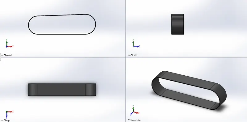
1. Transmission belt: This is used for transmission power. It is a flexible material linked between two shafts.
Features used:
- Boss extrude
- Fillet
Views of transmission belt:
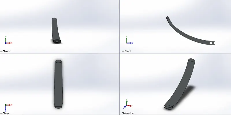
2. Kickstand: It is a piece of metal used to aid the vehicle instead of falling on the ground.
Features used:
- Loft
- Dome
- Cut extrude
- Split
- Boss extrude
- Fillet
Views of kickstand:
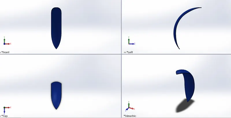
3. Front fender: It is a frame that prevents the tire from mud, sand particles, liquids etc.
Features used:
- Revolve boss/base
- Split
- Fillet
Views of front fender:
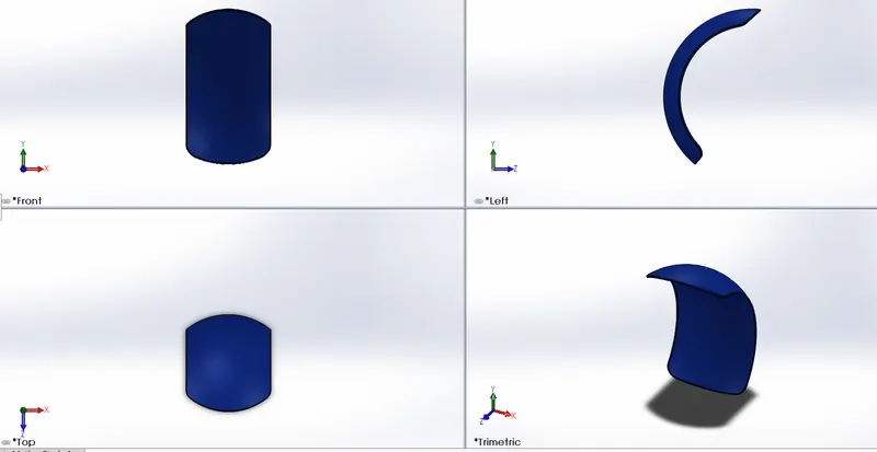
4. Rear fender: It is a frame that prevents the tire from mud, sand particles, liquids etc.
Features used:
- Revolve Boss/Base
- Split
- Fillet
- Shell
Views of rear fender:
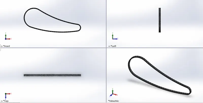
5. Chain: It is formed by connecting links. It is used to transmit power from the engine to the wheel.
Features used:
- Extrude Boss/Base
- Fillet
- Projected Curves
- Curve pattern
- Mirror
Views of Chain:
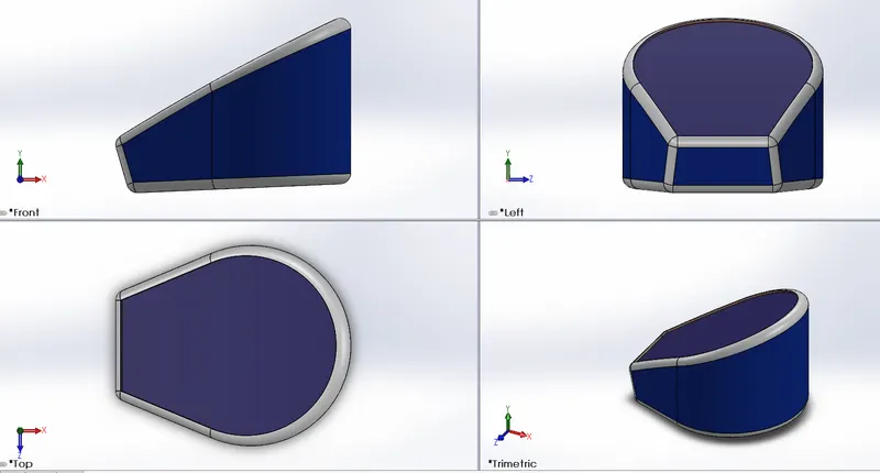
6. Oil tank: It is used to store the oil which is used to lubricate the engine parts for smooth performance.
Features used:
- Extrude Boss/Base
- Fillet
- Shell
- Combine
All views of oil tank:
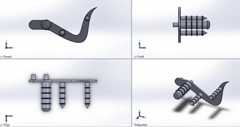
7. Pedal: It is a metal piece used for resting feet and also for shifting gears and applying brakes.
Features used:
- Extrude Boss/Base
- Fillet
- Revolve Boss/Base
- Dome
- Chamfer
- Linear pattern
All views of Pedal:
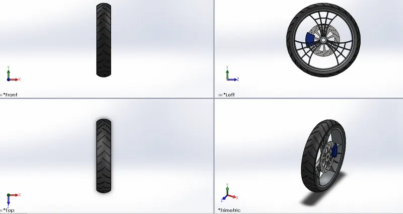
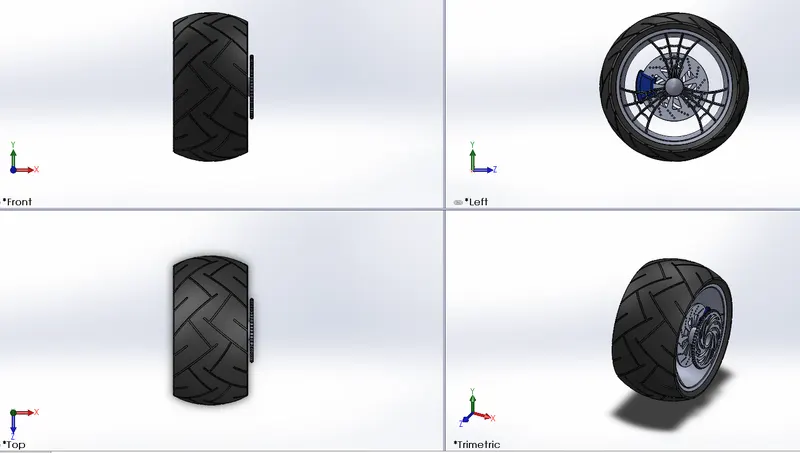
8. Front wheel: It is aiding the vehicle and driven wheel to move forward. The wheel contains the rim, tire, disc and calliper.
Features used:
- Extrude Boss/Base
- Cut extrude
- Revolve cut
- Circular pattern
- Combine
- Fillet
- Chamfer
All views of the Front wheel:
9. Rear wheel: It is a driven wheel from the source of the engine. The wheel contains the rim, tire, disc, sprocket and calliper.
Features used:
- Extrude Boss/Base
- Cut extrude
- Revolve cut
- Circular pattern
- Combine
- Fillet
- Chamfer
All views of rear wheel:
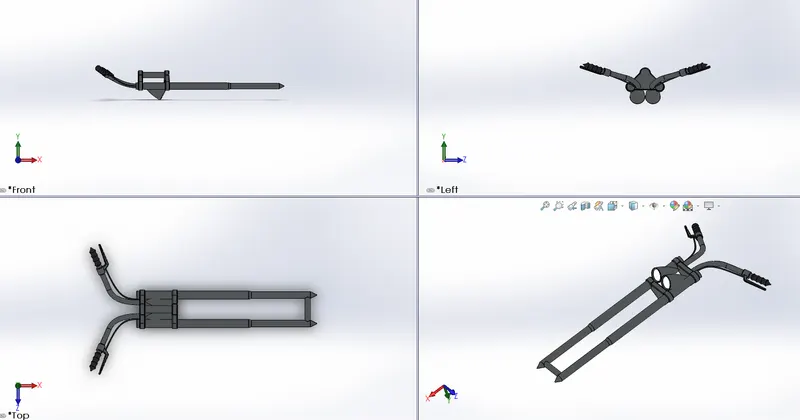
10. Front fork: It is mixed with various shapes. Cylindrical pipes for suspensions, and handle for holding the vehicle and some applications to run the vehicle. It is used to hold and steer the vehicle.
Features used:
- Extrude Boss/Base
- Revolve Boss/Base
- Fillet
- Extrude cut
- Dome
- Revolve cut
- Swept Boss/base
- Project curve
- Mirror
- Combine
All views of front fork:
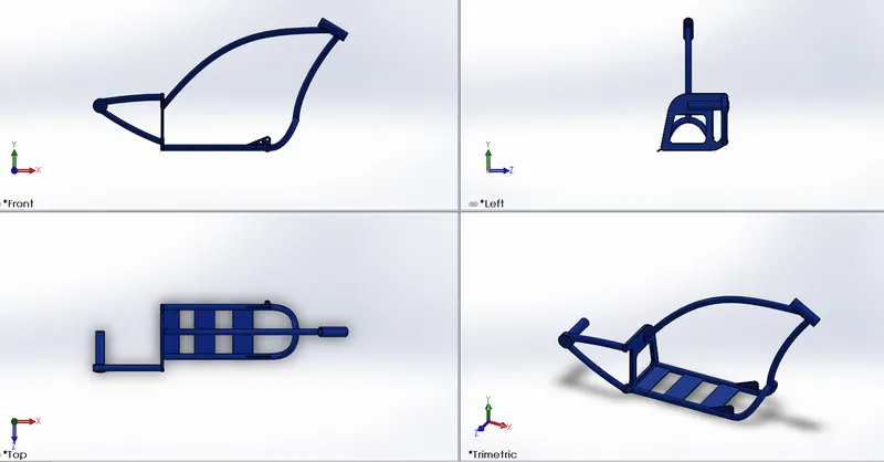
11. Chassis: It a frame designed to hold and protect the vehicle and person and all parts of it.
Features used:
- Swept Boss/Base
- Project curve
- Mirror
- Extrude Boss/Base
- Fillet
- Extrude cut
- Dome
- Combine
- Chamfer
- Split
- Revolve Boss/Base
All views of chassis:
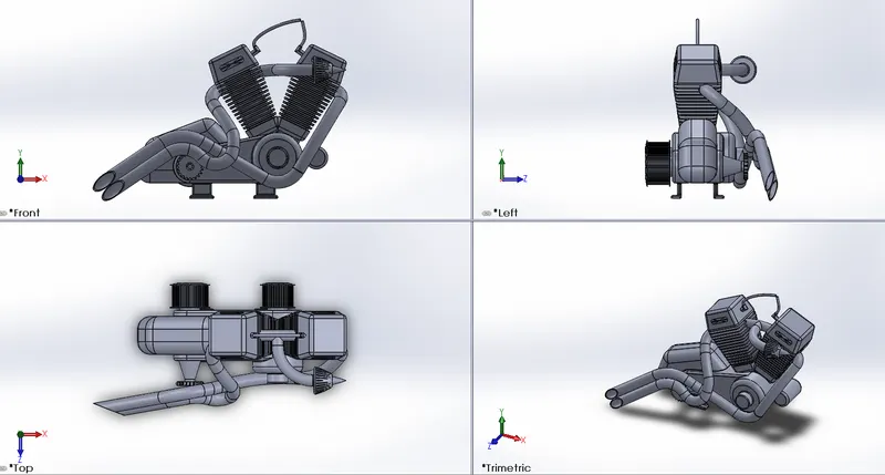
12. Engine: It is the source of power transmission to various parts. In this model, it consists of fins, valves, gearbox, electric motor, sprocket, exhaust pipes, pulleys and air filters.
Features used:
- Swept Boss/Base
- Project curve
- Mirror
- Extrude Boss/Base
- Fillet
- Extrude cut
- Dome
- Combine
- Chamfer
- Split
- Revolve Boss/Base
- Linear pattern
- Circular pattern
- Composite curve
All views of engine:
13. Gas tank: It is a storage container for fuels. The fuel stored is sent into the engine for power. Fuels exhaust inside the engine to give power after rotations in components.
Features used:
- Surface loft
- Surface knit
- Project curve
- Fillet
- Swept surface
- Split
- Mirror
- Swept cut
- Plane
All views of gas tank:
Assembly of an American Chopper:
Mating relations:
- Concentric: Same profiles of two different models are joined together using this relation.
- Coincident: Face or edges where two of them are joined together using this relation.
- Width: When one model is distant from one another, this relation is used.
- Parallel: It is used to place in parallel relation between any two faces or edges etc.
- Limit angles: Used to rotate the components at certain angles.
Steps followed for assembly:
- Insert all components
- Drag chassis
- Drag other components one by one.
- Apply mating relations with chassis or wherever required.
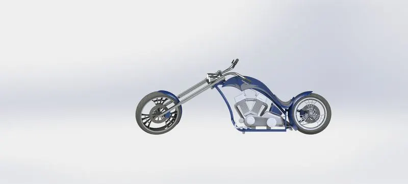
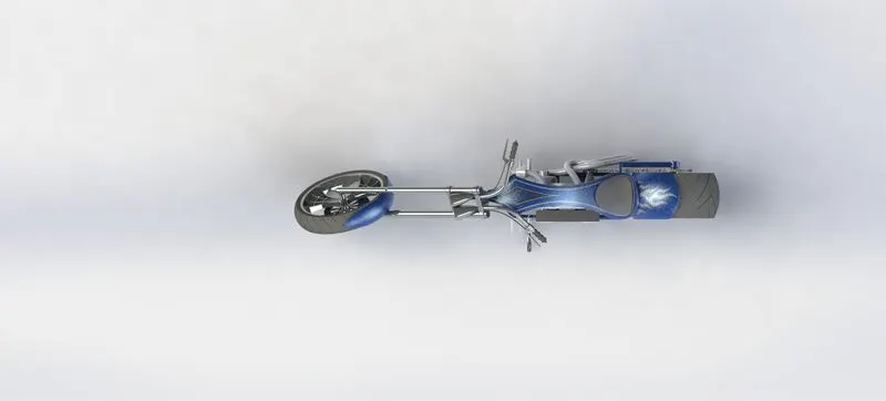
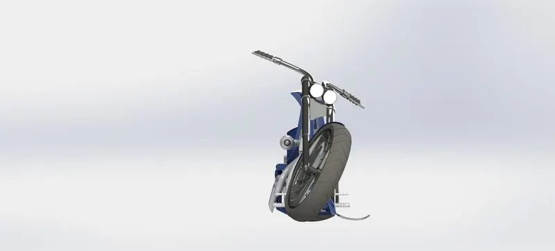
Assembled views of American Chopper:
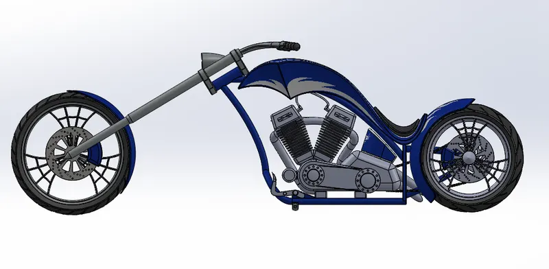
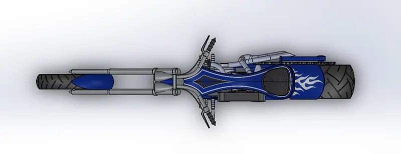
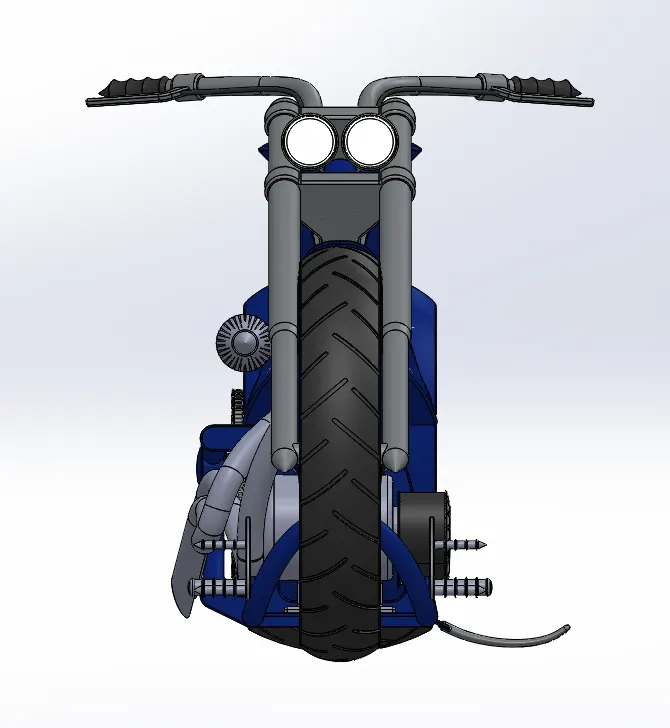
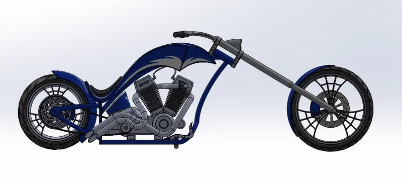
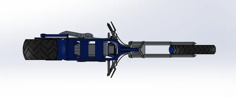
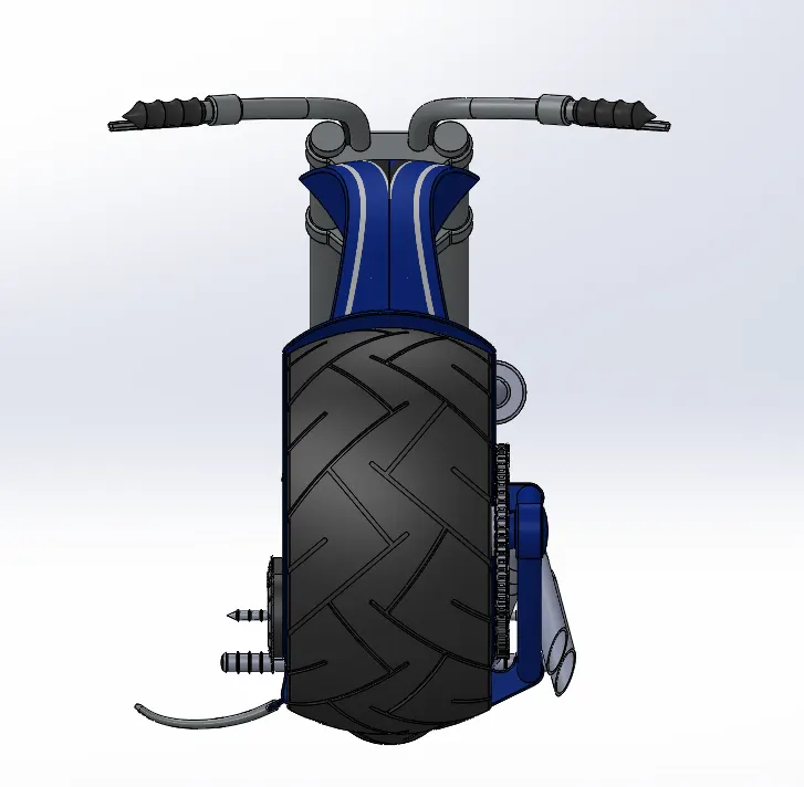
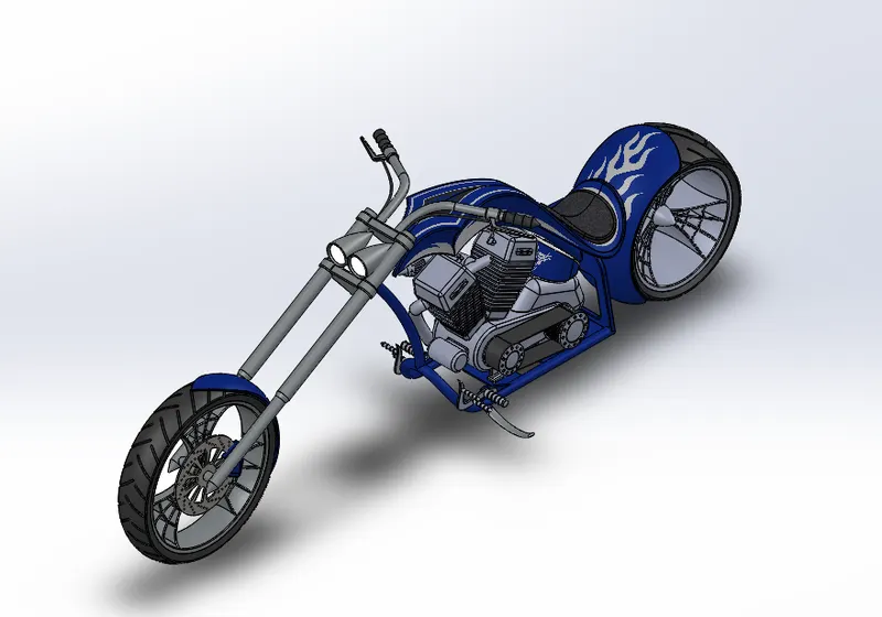
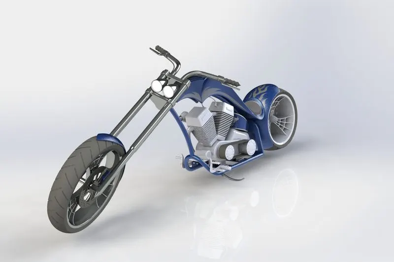
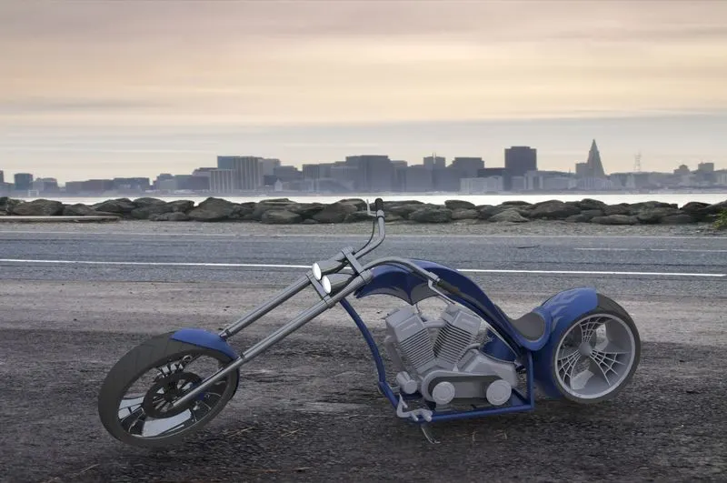
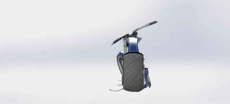
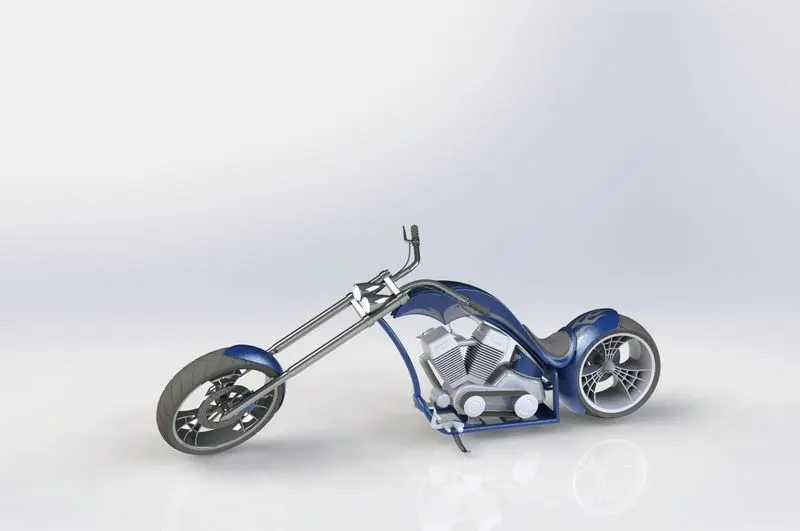
Rendering: This is a process where the CAD model is represented in a realistic view. This can be done by Solidworks PhotoView360 and Solidworks Visualise.
The realistic view is obtained from applying materialistic views to all components in the assembled model and adding camera views and perspective views to the model. Adding some background images to the model gives a more realistic model. Apply some decals to the models for a more realistic appearance.
These are done by adjusting the model like brightness, size, reflection etc., with the respective methods and rendering is done to obtain the image.
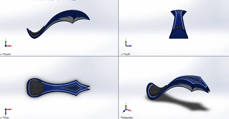
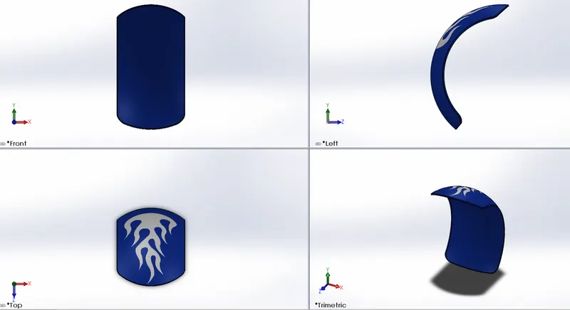
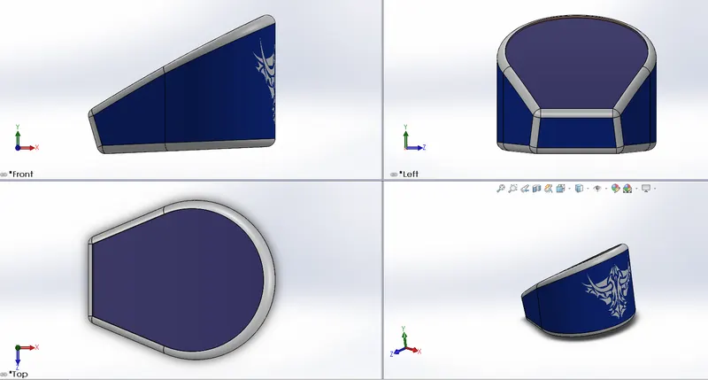
Decal adding to individual models:
1. Gas tank decal:
2. Decal on rear fender:
3. Decal on oil tank:
Rendering:
Some rendered images of American Chopper: The images are rendered by keeping lights, cameras and ambience. Different kinds of scenes are available in Solidworks.
Points to remember:
- Always the sketch should be fully defined.
- The sizes of individual models should be checked for avoiding differences in assembly.
- The mating relations should be given correctly in assembly.
- The appearances in realistic view should be more efficient than the model designed.
- Camera, size and lightning adjustments need to be done carefully while rendering.
- Plane and view notations of individual components should match with assembly.
CAD models: All parts and assembly of American Chopper
Conclusion: American chopper individual parts modelled and assembled using Solidworks. Rendering is done using Solidworks PhotoView360 and Solidworks Visualise.