Multi-cell Battery Pack
Q) How does the weakest cell limit the usable capacity of the entire battery pack? What is the solution?
The 'weakest cell' is defined as the cell which limits the entire operation of the battery pack. It is the decider of how much the battery pack can be charged or discharged, and whether or not its maximum potential can be utilized.
Individual cells in a battery pack may have different capacities, hence resulting in different SOCs. This could be due to reasons such as varying internal resistance of cells, manufacturing variances, assembly variances, and more. Over a period of time, factors such as differences in cell temperature (due to some cells receiving more natural convective cooling for instance) also add on, which creates an imbalance in the entire pack. These are the reasons as to why cell imbalancing happens.
Theoretically, all cells should be charged together at the same rate and to their voltage limits (which are supposedly identical). Likewise, they should all discharge at the same rate, and hence all of their SOCs should be the same at all periods. However, in reality, this isn't the case because of unintentional differences in the cell's internal reactions, and factors mentioned previously. The solution is cell balancing.
WHAT IS CELL BALANCING?
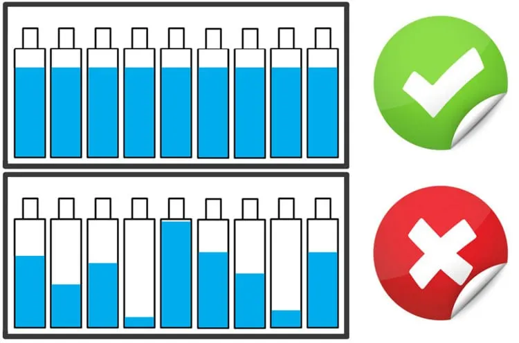
Cell balancing is a technique in which voltage levels of every individual cell connected in series to form a battery pack are maintained to be equal to achieve the maximum efficiency of the battery pack. When different cells are combined together to form a battery pack it is always made sure that they are of the same chemistry and voltage value. However, once the pack is installed and subjected to charging and discharging, the voltage values of the individual cells tends to vary. This variation in voltage levels causes cell unbalancing which will lead to problems such as:
-
Thermal Runaway: Lithium cells are very sensitive to overcharging and over-discharging. In a pack of four series-connected cells, if the voltage limit is 3.5V and one cell has already reached 3.5V while the others are at 3.2V, continuing to charge the 3.5V cell (since the other cells still require charging) to even 3.55V could cause the battery to explode or catch fire. Although these days BMS controls disconnect the charger/load before overcharging/over-discharging, operating outside the cell's safety limits can have serious effects on the pack
- Cell degradation: a slight increase in charging voltage from 3.5V to 3.55V will degrade the battery faster by 30%, reducing efficiency and cycle life significantly
-
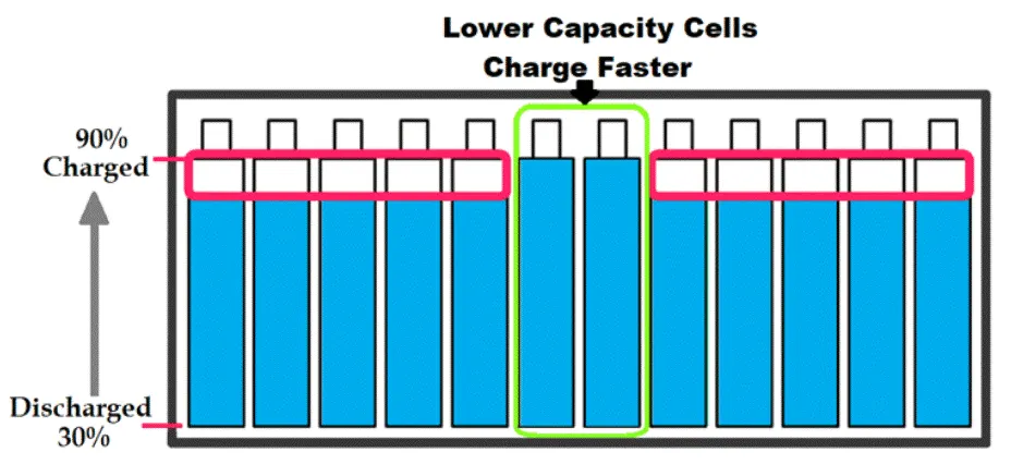
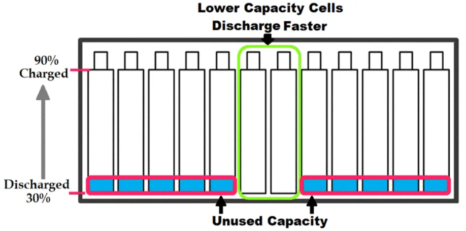
Incomplete use of pack energy: As the batteries in a pack get older, few cells might be weaker than its neighboring cells. These weak cells will be a problem since they will charge and discharge faster than a normal healthy cell. While charging a battery pack with series cells the charging process should be stopped even if one cell reaches the maximum voltage. This way the if two cells in a battery pack get weak they will charger faster and thus the remaining cells will not be charged to its maximum as shown below. Similarly, when the battery pack is being discharged, the weaker cells will discharge faster than the healthy cell and they will reach the minimum voltage faster than other cells, disconnecting the pack from the load even if one cell reaches the minimum voltage. This leads to the unused capacity of the pack energy as shown below.
METHODS OF CELL BALANCING:
- Passive cell balancing: simplest method of all - it can be used in places where cost and size are major constraints.
- Charge shunting: in this method a dummy load like a resistor is used to discharge the excess voltage and equalize it with other cells. These resistors are called as bypass resistors or bleeding resistors. Each cell connected in series in a pack will have its own bypass resistor connected through a switch as shown below.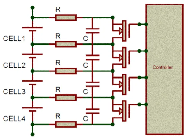
As is evident, each of the four cells above are connected to two resistors each, which are then connected to capacitors, MOSFET, and controller. The controller measures the voltage of all cells, determines which cell needs to dissipate voltage and accordingly turns on the MOSFET of that cell. The cell then begins to discharge through the resistors.
This method is not very efficient because electrical energy is dissipated as heat in the resistors and the circuit also accounts of switching losses. Another drawback is that the entire discharge current flows through the mosfet which is mostly built into the controller, and hence the discharge current has to be limited to low values which increases the discharging time. This can be fixed but that is beyond the scope of this report.
- Active cell balancing: much more efficient method, as the extra voltage energy isn't wasted as heat and is instead used to equalize another cell that's low on charge. This is achieved by utilizing charge storing elements like capacitors and inductors.
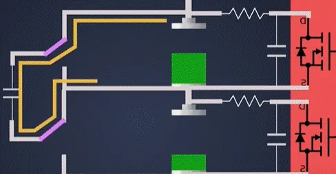
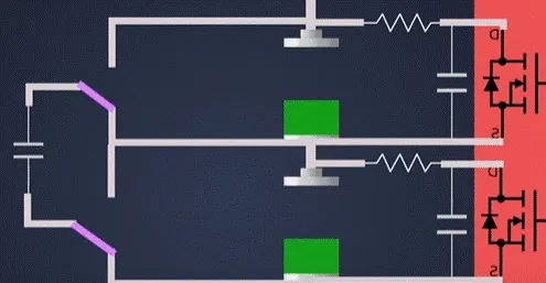
- Charge Shuttles (Flying Capacitors): A capacitor is switched sequentially by first being connected to the cell with higher voltage, storing the extra voltage from the cell, then connecting itself to the cell with lower voltage and equalizing it. Due to the capacitor having to charge and then discharge, this can be a time consuming procedure. Another disadvantage of this method is that the extra charge can only be transferred across adjacent cells.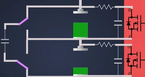
- Inductive converter (Buck-Boost method): Let's say cell 1 has the higher voltage. SW1 is turned on, causing voltage from Cell 1 to flow to the inductor L, which stores the energy. Once L is fully charged, SW1 is turned off and SW2 is turned on. With nothing to hold the inductor's magnetic field energy, it starts to discharge itself into Cell 2 until L is fully discharged. Then SW2 is turned off, SW1 is turned on and the process repeats.
The disadvantage of this method is that, voltage can only be transferred from the higher cell to the lower one.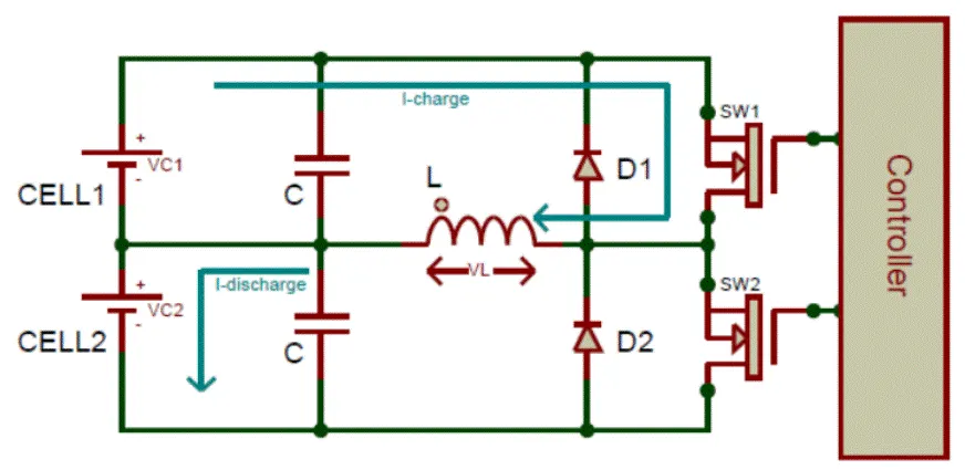
- Inductive converter (Fly back based): the problem of voltage only being able to be transferred from the higher to lower cell can be avoided with this method. In a flyback type converter, the primary side of the winding is connected to the battery pack and the secondary side is connected to each individual cell of the battery pack as shown below.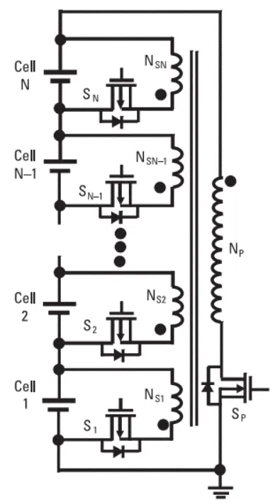
The primary transformer, Np, will take pulses of energy from all the cells instead of from the cell(s) that have higher than average voltage. Once this is done, the MOSFET of those lower voltage cells are opened and the stored charge in the primary winding can be transferred to the secondary winding(s). This allows the overall battery pack to discharge into the weaker cell(s).
The biggest advantage of this method is that charge does not need to be transferred from a single higher voltage cell, and any weak cell can attain charge from the entire pack. However, because this is a transformer setup, the complexity and space requirement is high.