Air Standard Otto Cycle: Piston Kinematics using MATLAB
Aim:
- To construct and analyze an Otto Cycle
Objectives:
- Plot a Pressure-Volume graph
- Calculate the thermal efficiency of the cycle
Introduction:
An Otto Cycle is a thermodynamic cycle that represents the functioning of Spark Ignition (SI) internal combustion engines.
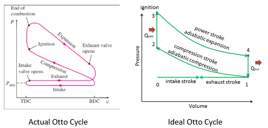
The ideal cycle approximates the processes of SI engines as is evident from the P-V diagram of an actual cycle. The ideal cycle has sharp corners because the shift from one process to the next is considered instantaneous, whereas in actuality it all happens at a finite rate.
The processes are as follows:
- 0 – 1: air and fuel are drawn into the chamber at constant pressure as the intake valve opens. This pushes the piston from top dead centre (TDC) to bottom dead center (BDC).
- 1 – 2: The piston moves from BDC to TDC to compress the air/fuel (A/F) mixture. This increases the pressure inside the chamber. Since no heat is added or expelled, this is considered a reversible adiabatic compression (isentropic) procedure.
- 2 – 3: At reaching point 2, the A/F mixture meets the spark plug, which instantly ignites this mixture and results in combustion. This drastically increases the pressure inside the chamber. This process happens quickly enough that the change in the position of the piston can be considered negligible, hence a constant volume heat addition procedure.
- 3 – 4: The pressure and energy created by the combustion pushes the piston from TDC to BDC, increasing the volume of the chamber. This is known as the power stroke of the cycle, as this is where the generated thermal energy is converted into kinetic energy of the moving piston, which finally results in the rotational and/or translational movement of the machine. Since no heat is added or expelled, this is considered a reversible adiabatic expansion (isentropic) procedure.
- 4 – 1: The heat from the remaining gas leaves, which results in the lowering of the kinetic energy of the molecules, and hence the decrease in pressure. This happens while the piston is at BDC.
- 1 – 0: The exhaust produced in the chamber due to the combustion is expelled out as the exhaust valve opens. The piston comes back to TDC.
Formulas:
- Swept Volume: volume swept by the piston during its motion
`V_s = pi/4 * d_b^2*l_s` [where `d_b` is the diameter of the bore and `l_s` is length of stroke]
- Clearance Volume: difference between the position of the piston and the TDC
`V_c = V_s / (C_r - 1)` [where `C_r` is compression ratio`]
- Total Volume:
`V_t = V_s + V_c`
- Reversible Adiabatic Process (Isentropic):
`P_aV_a^(gamma) = P_bV_b^(gamma) -> PV^(gamma)` = Constant [where `gamma` = ratio of specific heats of fluids]
- Combined Gas Law:
`(P_aV_a)/(T_a) = (P_bV_b)/(T_b) -> (PV)/T =`Constant
- Change of volume inside the combustion chamber:
`V/V_c = 1 + 1/2(C_r -1 )[R+1 - costheta - sqrt(R^2-sin^2theta)]` [where `theta` is the corresponding angle of the crankshaft depending on the position of the piston, and R is the ratio of the length of the connecting rod to the crankpin radius (`l_s/2`)
- Thermal efficiency of Otto Cycle: the ratio of useful work done to amount of energy input
`eta = 1-(1/(C_r^(gamma-1)))`
Code for Main Program:
%plotting otto cycle

%Inputs
gamma = 1.4;
p0 = 101325;

%State 1 variables
p1=101325; %in Pascals
t1=550; %in Kelvin


%Engine parameters (in meters)
bore=0.5;
stroke=0.1;
connecting_rod=0.15;
c_r=3;

%Calculating swept and clearance volume
v_swept = (pi/4)*bore^2*stroke;
v_clearance = v_swept/(c_r - 1);
v1 = v_swept + v_clearance;
v2 = v_clearance;

%State 2 variables
p2 = p1*(c_r^(gamma));
t2 = p2*v2*t1/(p1*v1);

constant_compression = p1*v1^(gamma);
V_compression = engine_kinematics(bore, stroke, connecting_rod, c_r, 0, 180);
P_compression = constant_compression./V_compression.^gamma;

%State 3 variables
v3 = v2;
t3 = 2300;
p3 = p2*t3/t2;

constant_expansion = p3*v3^(gamma);
V_expansion = engine_kinematics(bore, stroke, connecting_rod, c_r, 180, 0);
P_expansion = constant_expansion./V_expansion.^gamma;

%State 4 variables
v4 = v1;
p4 = p3*(v3/v4)^(gamma);

thermal_efficiency = 1 - (1/(c_r - 1)^(gamma - 1));


%if marking with "*" were needed:
%plot(v2,p0,'*','color','k')
%plot(v1,p1,'*','color','k')
%plot(v2,p2,'*','color','k')
%plot(v3,p3,'*','color','k')
%plot(v4,p4,'*','color','k')

hold on

line([v2 v1],[p0 p1],'linewidth',1,'color','[0.5 0 0]')
plot(V_compression, P_compression,'linewidth',1,'color','b')
line([v2 v3], [p2 p3],'linewidth',1,'color','r')
plot(V_expansion, P_expansion,'linewidth',1,'color','g')
line([v4 v1], [p4 p1],'linewidth',1,'color','m')

grid on
xlabel('Volume','fontsize',10)
ylabel('Pressure','fontsize',10)
axis([0 0.04 0 1.4*10^6])
title('Otto cycle - PV graph','fontsize',12)
legend('intake/exhaust','compression','combustion','expansion','heat rejection')

text(v2,p0,'0')
text(v1,p1,'1')
text(v2,p2,'2')
text(v3,p3,'3')
text(v4,p4,'4')
text(0.0225,7*10^5,['Thermal efficiency = ' num2str(thermal_efficiency)],'fontsize',10)
Code for Function:
function [V_compression] = engine_kinematics(bore, stroke, connecting_rod, c_r, start_crank, end_crank)

%inputs
crankpin_radius = stroke/2;
R = connecting_rod/crankpin_radius;

v_swept = (pi/4)*bore^2*stroke;
v_clearance = v_swept/(c_r - 1);

theta = linspace(start_crank,end_crank,180);

term1 = 0.5*(c_r - 1);
term2 = R + 1 - cosd(theta);
term3 = (R^2 - sind(theta).^2).^(0.5);

%how the volume inside the combustion chamber changes
V_compression = (1+term1*(term2-term3))*v_clearance;

end
Final output:
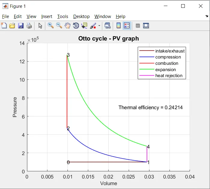
Conclusion:
The thermal efficiency of an Otto Cycle depends on the compression ratio of the engine and the ratio of specific heats of fluids. In this experiment, I have selected a relatively smaller compression ratio of 3, while the average, for a four-stroke cycle SI engine, lies between 4 and 8. The diameter of my bore is also five times as much as my stroke length, as can be referred to in the code, as my goal was to have an engine that could generate more power. The combination of a smaller compression ratio and a larger bore relative to the stroke length will directly lead to an engine with higher RPM and greater power generation at the expense of thermal efficiency, as is evident from the computed efficiency in the graph above. In contrast, if higher thermal efficiency was demanded, a longer stroke relative to the bore diameter and a higher compression ratio would be the inputs.