Modelling of 25 storey building with the specified properties using ETABS
Aim- to model a 25 storey building in etabs and analyse it.
Procedure-
- Open etabs 2019.
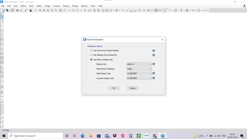
- Select new model and set the model initialization> use built in setting. Specify the model as Indian code.
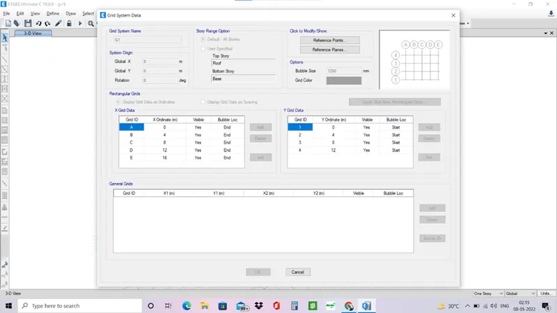
- Set the grid system for the model.
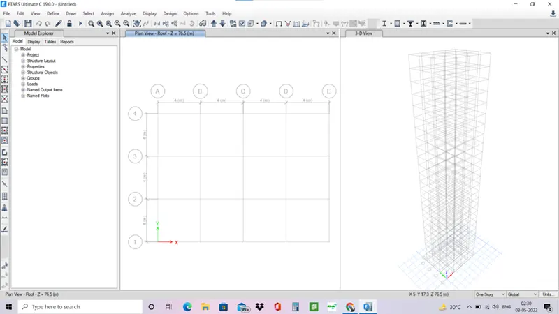
- Set the storey system for 25 floor in the system with height 3m between floors and plinth level of 1.5m.
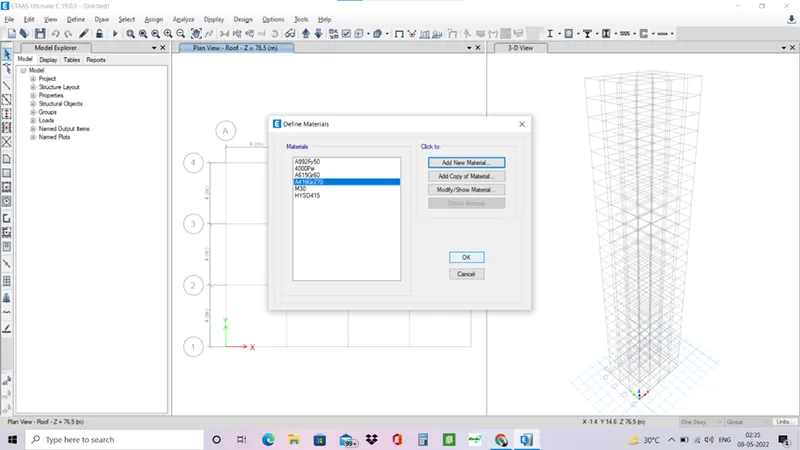
- Now add the material property in the model.
- Define>material properties>add new material>m30 and Hysd415.
- Similarly define the frame sections for beam and columns.
- Define>section properties>frame sections>add new property>select rectangular section.
- Write B 300x400 and modify the the frame section data. Set the depth and width and reinforcemnet data. Similarly do it for column and slab.
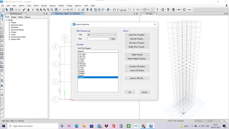
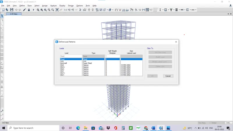
- Now add load patterns in the model.
- Define>load patterns>add new load.
- Dead is already defined rest of the loads are to be added.
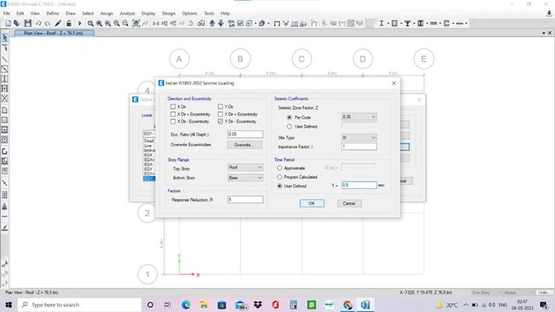
- Modify the seismic loads for eccentricity and directions.
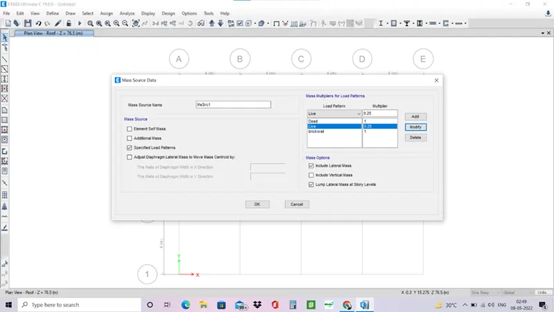
- Add mass source, define>mass source>modify mass source.
- Add the load patterns in the mass source. Dead load, wall load and live load.
- Also add the load combinations for the model.
- Define>load combinations>add default load combinations.
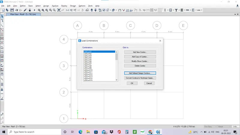
- Now add the columns, beams, and slab in the model.
- Go to 1st floor which is master storey select all stories.
- Select quick draw columns and select C 800x800 from properties.
- Carefully place the columns on the grids intersection.
- Select quick draw beams and select B 300x400 from from property and place the beam between the columns.
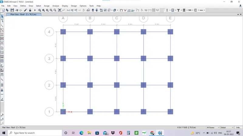
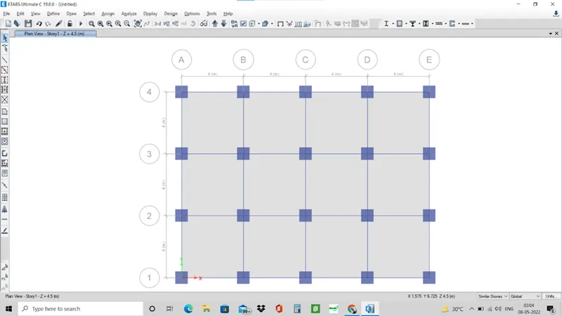
- Now add the slabs in the model.
- Select the similar stories option to avoid placing the slabs on the plinth level.
- Select quick draw floor and select slab 150 and place it carefully.
- Go to base floor add restraint of pin foundation to the model.
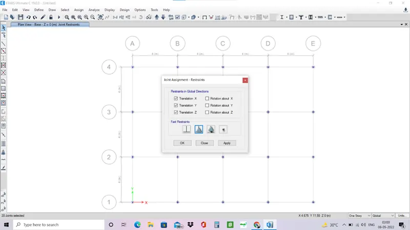
- Now add loads on the building.
- Select>object type>beams.
- Assign>frame loads> loads assignment.
- Select brick wall and make it 10 kn/m2 as specified.
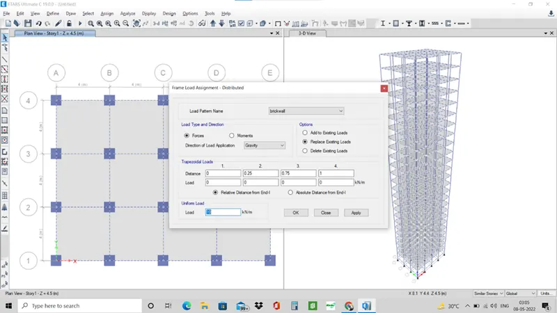
- Similarly, select> object type> floors.
- Assign> shell loads> uniform> shell load assignment.
- Select live load and set it at 3kn/m2.
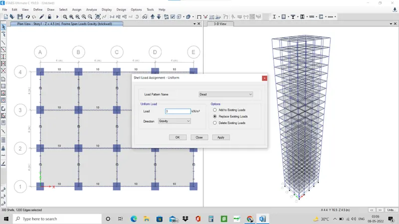
- Add the diaphgram to the model for centre of mass.
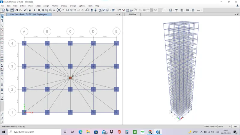
- Now check the model for any errors.
- Run analysis on the model.
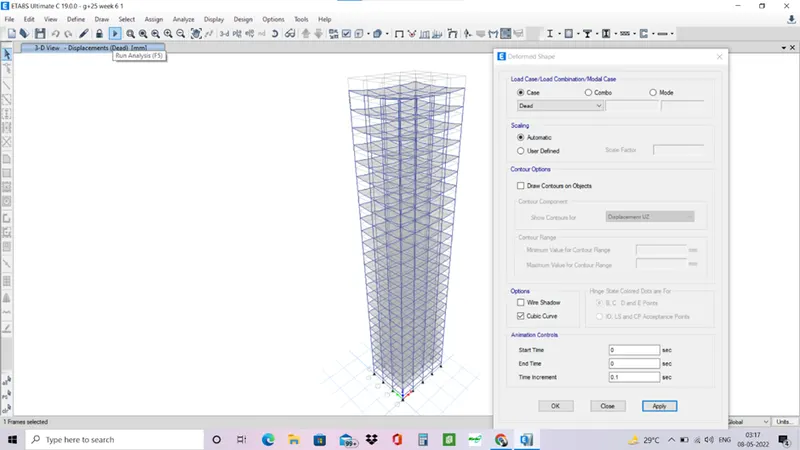
- Go to display> show tables.
- Select analysis report> structure output> modal information.
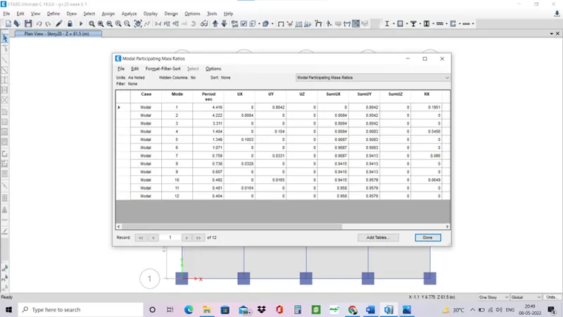
- Select the modal participating mass ratio.
Result-
- the translational fundamental natural period in both x and y directions is respectively 4.416s and 4.222s.
- mode 3 is 3.311 which is lesser than mode 1 and mode 2 therefore the torsional irregularity is satisfied.
- The first mode itself is having 80% of the mass participation factor therefore no need to add next two mode for x and y directions.
- But the 10% difference between 1st mode and 2nd mode is not satisfied.