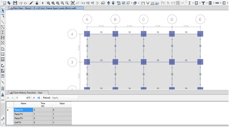
Modelling of 25 storey building with the specified properties using ETABS
Question :
Model a 25 storey building on ETABS with structural properties as specified below. Ground floor or plinth floor level can be taken at a height of 1.5 metres from the base. Each of the successive 25 storeys has a storey height of 3 metres.
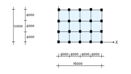
Structural Element Sizes
- Beams : 300 × 400 mm
- Columns : 800 × 800 mm
- Slab : 150 mm thick
Material Properties
- Grade of Concrete : M30
- Grade of Steel Reinforcement Bars : Fe 415
ANS
Aim : Model a 25 storey building on ETABS with structural properties as specified below. Ground floor or plinth floor level can be taken at a height of 1.5 metres from the base.
Each of the successive 25 storeys has a storey height of 3 metres.
Apparatus : Etabs installed software , model Initilazation , Grid system , Draw tool bar, Select , Asign , define , View , edit.
Procedure :
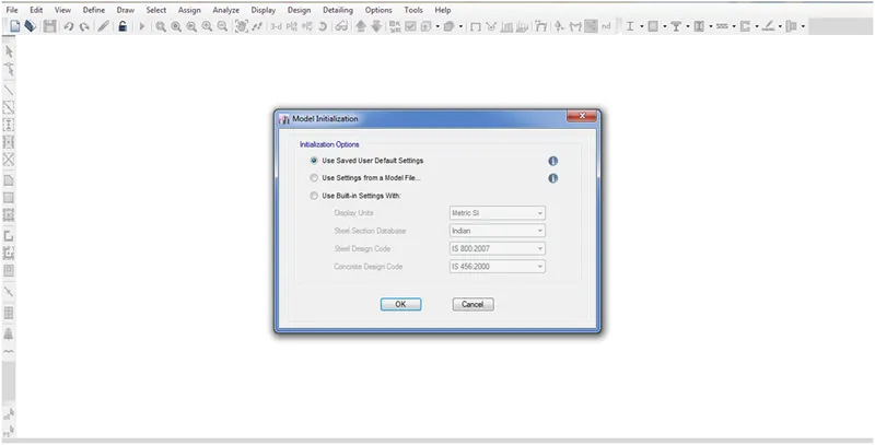
- Start etabs software in model Initialization use built in system setting Display units as metric , steel section Database indian , steel Design code as IS 800 : 2007 and concerte design code is IS 456:2000
- Click OK to display the grid settings
Fig 1
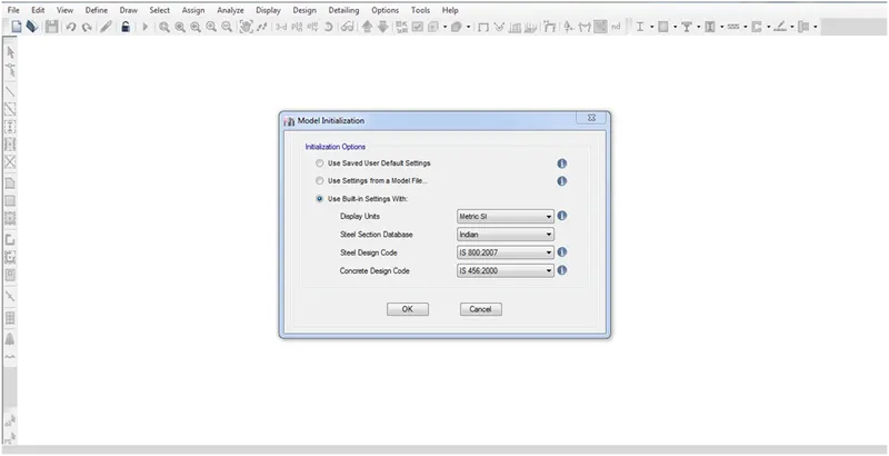
Fig 2
- In Grid settings set grid in X direction as 4 meter in each spacing and y direction as 4 meter as shown in below picture
Fig 3
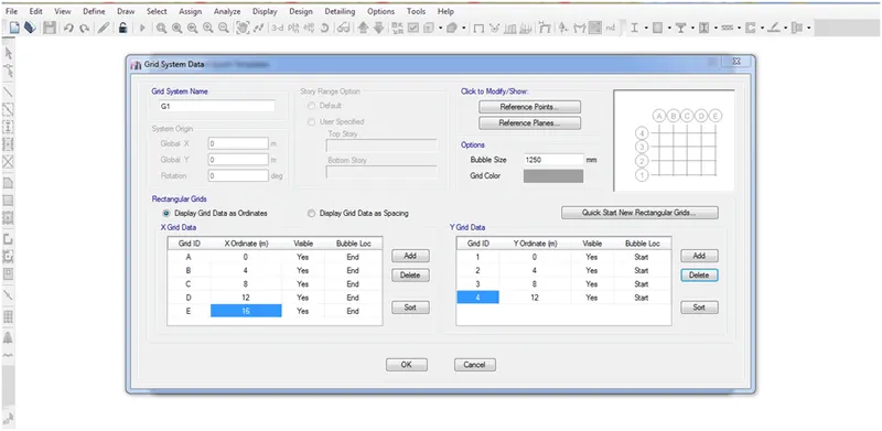
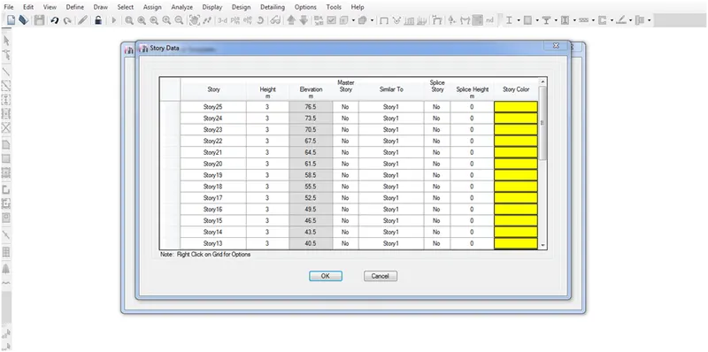
- Click on story Dimension custom spacing and click on edit story Data
- Click Story as 25 store and distance as from floor to floor as 3 meters
- Master story as first floor and remaining as similar to first floor
- etabs will automatic generate the height of the building as shown in fig 4
Fig 4
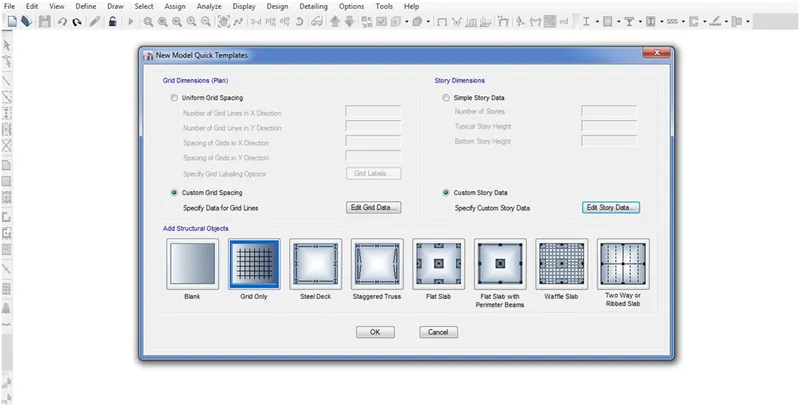
Fig 5
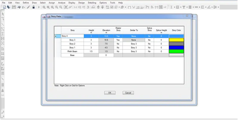
Fig 6
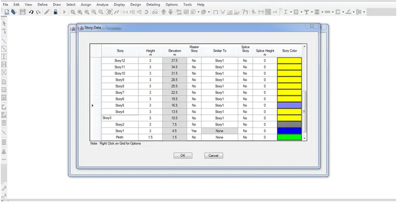
Fig 7
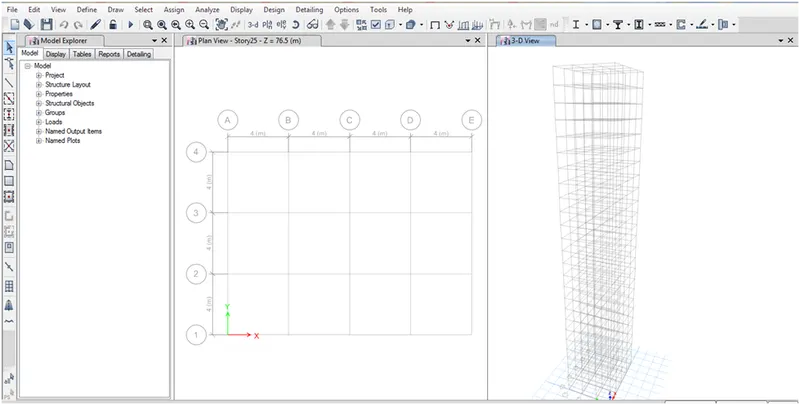
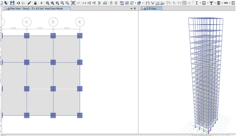
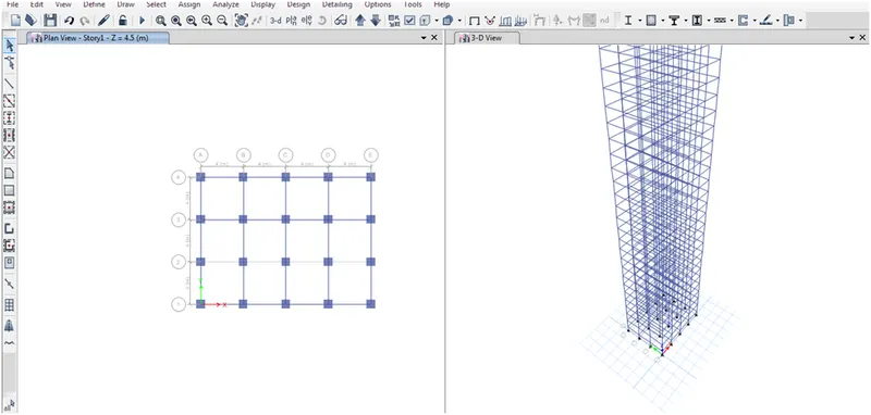
- The figure 8 shows the 3d view of 25 floors and the plan view of the 1st floor in a single frame this is happen after the all grid setting and the height settings are done
Fig 8
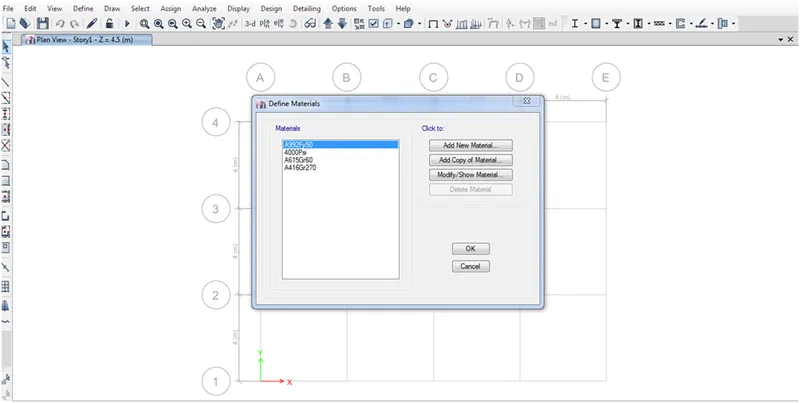
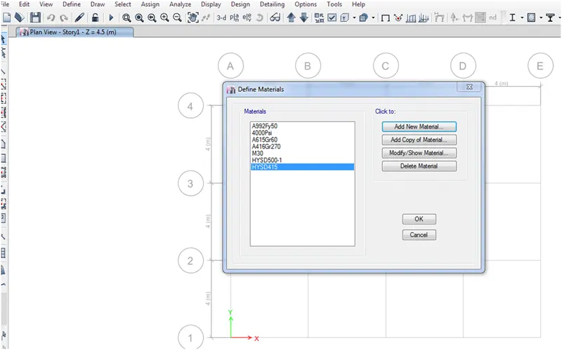
- To add the material property go to the define click on define material and click on add new material
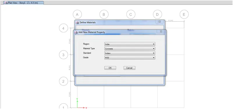
- Add the region as Indian , material type concrete , standerd indian , grade of concrete as M30
- The lightweight modification factor (l) recommended by the American Concrete Institute (ACI 318-08) shear design provisions was computed and ranged from 1.21 to 2.71 for all beam specimens.
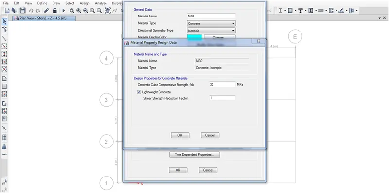
- To add the material property go to the define click on define material and click on add new material
- Add the region as Indian , material type concrete , standerd indian , grade of Steel as HYSD Grade 500
- Etabs will automatic generate the required data for the design code
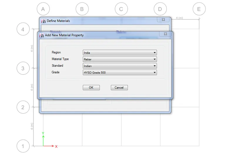
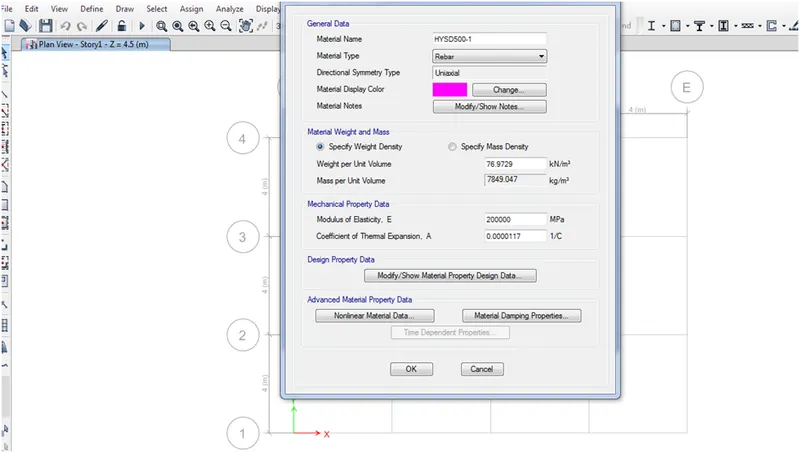
- To add the material property go to the define click on define material and click on add new material
- Add the region as Indian , material type concrete , standerd indian , grade of for contailment bar as HYSD415
- Etabs will automatic generate the required data for the design code
- We use only the non linear material
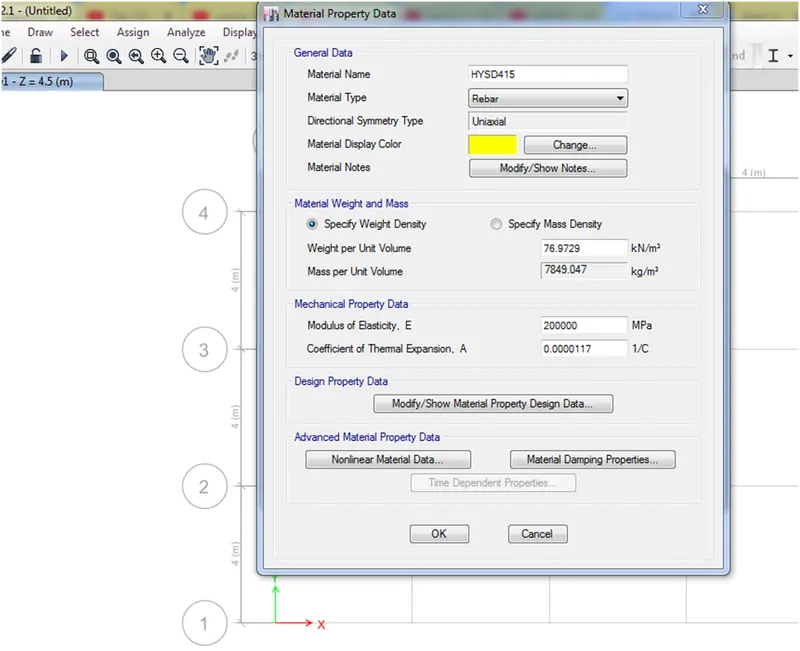
For shear reinforcement we use fe415
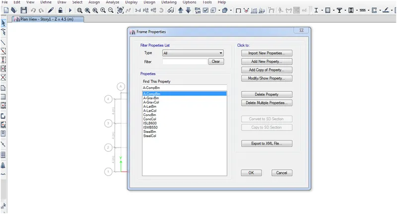
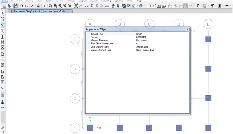
- For Beams and column go to define and section properties frame section
- Click on add new property material
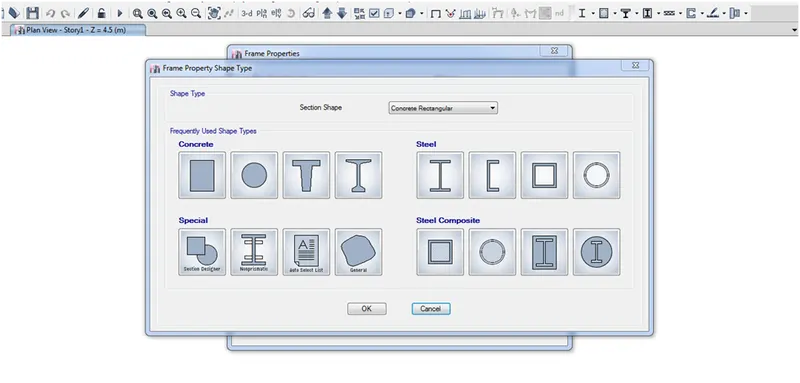
- Click on concrete
- Specify the name property as column and assign the size of column as 800mm X800 mm
- material type as concrete
- Also gave the dimension of the column as 800mm X800 mm
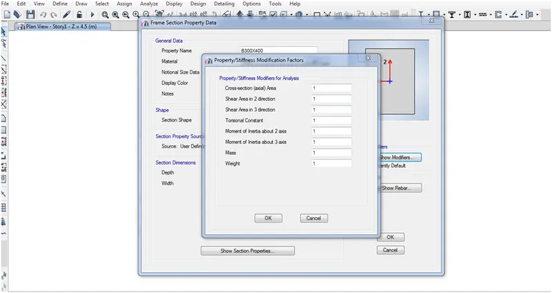
- Due to tracking takes place we take only 0.35 as per Is 1893
- Read clause 6.4.3.1 for structural analysis of beam the moment of inertia is about 35 %
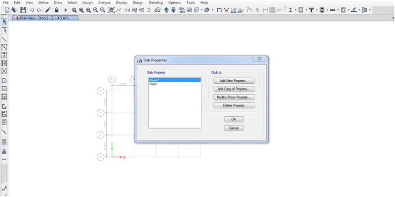
- Click on define and select the slab
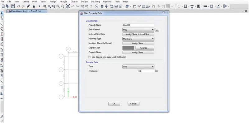
- Select the Slab property data and provide property data as slab 150 and material as M30
- Click type as slab and thickness of slab as 150mm
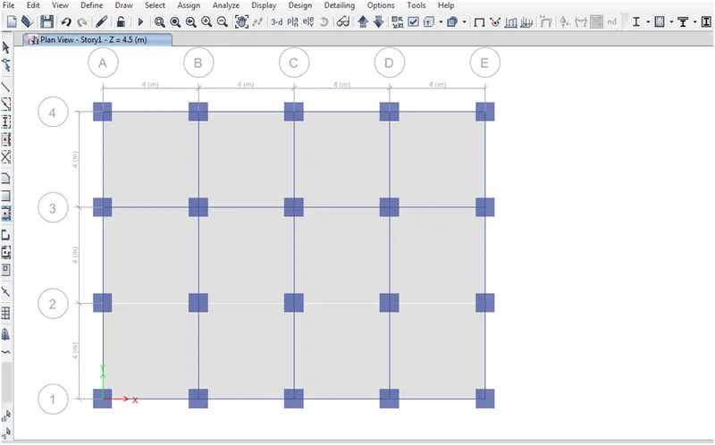
- For placement of column click on qucik place of column in left side of the toolbar
- In that select the column size as prescribed 800mmX800mm
- Etabs will automatically get the size of the column and the placement of the column on the grid will be done by left clicking
- As shown as figure below
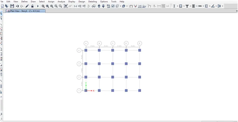
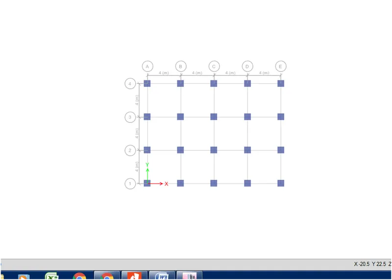
This is the sectional view of the Building below figure
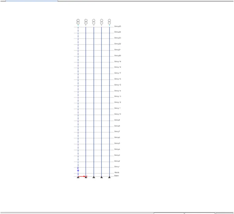
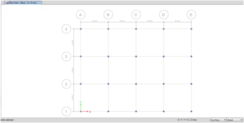
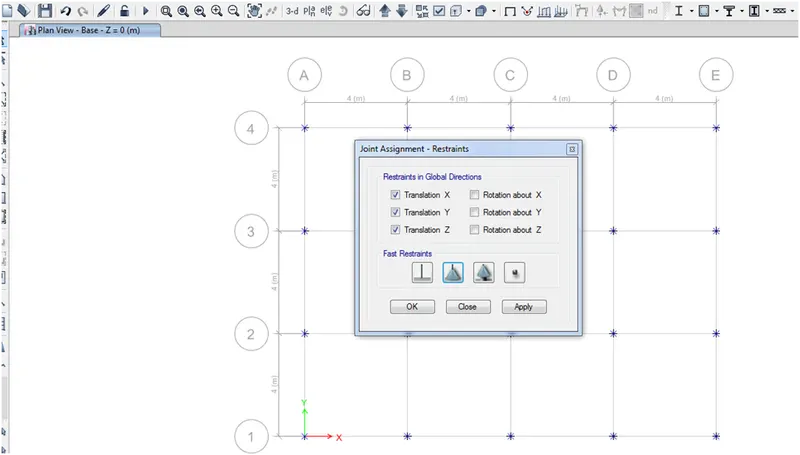
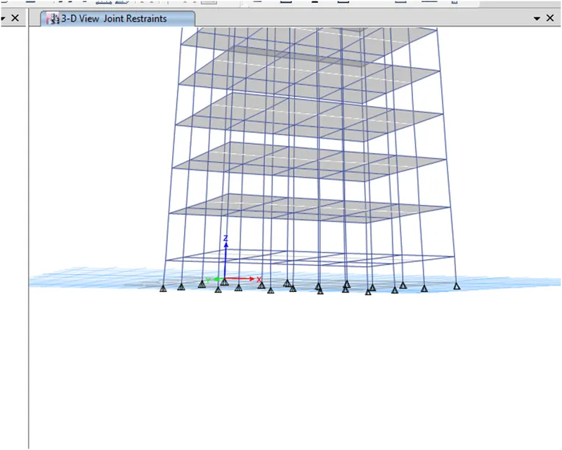
- At the base of the building the pin joint are provided as shown in figure below
- For the seismic load pattern the load are to added like the Dead load , live load , brick load , for the Dead load load value is 1 and for the live load 0 and brick load 1
- Also add earthquake load in X direction ,
- Earthquake load in -X direction
- Earthquake load in + X direction
- Earthquake load in -Y direction
- Earthquake load in +Y direction
- Earthquake load in Y direction
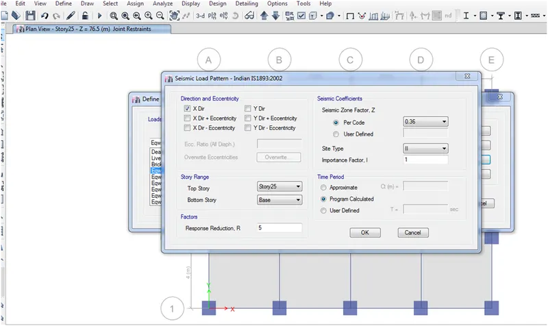
- Click on the direction of modify the Direction and the eccentricity are in X direction and the Responce reduction factor as 5 and soil type is zone II
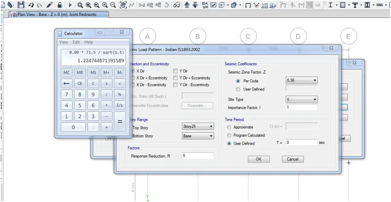
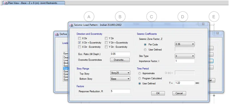
- The time period is taken as 1.22 sec as formulated in IS 1893:2016
- shown in figure below
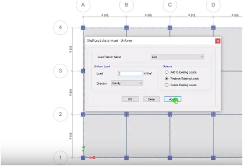
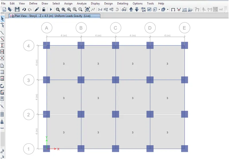

The load acting of the bulding in the direction of the gravity in -z direction
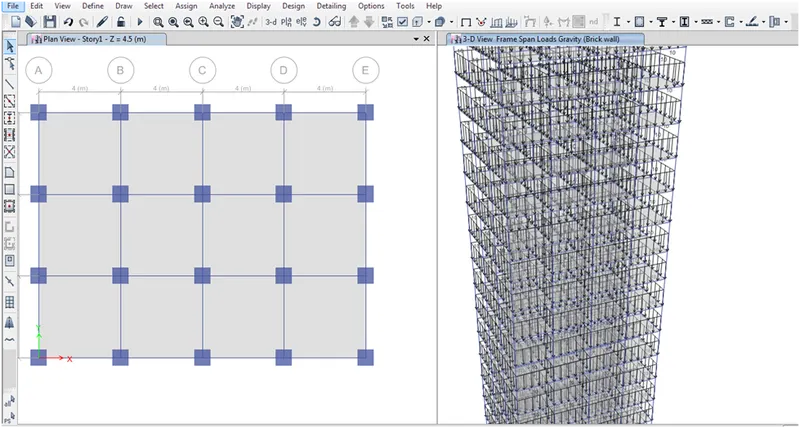
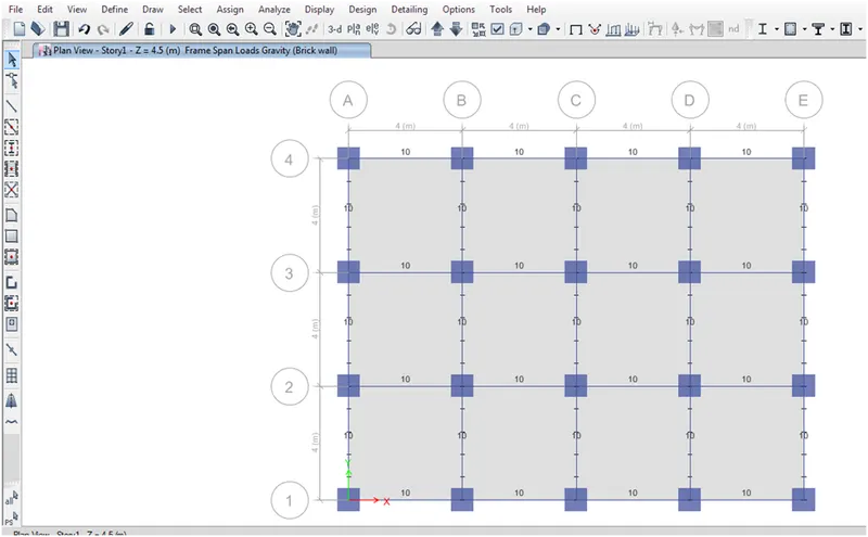
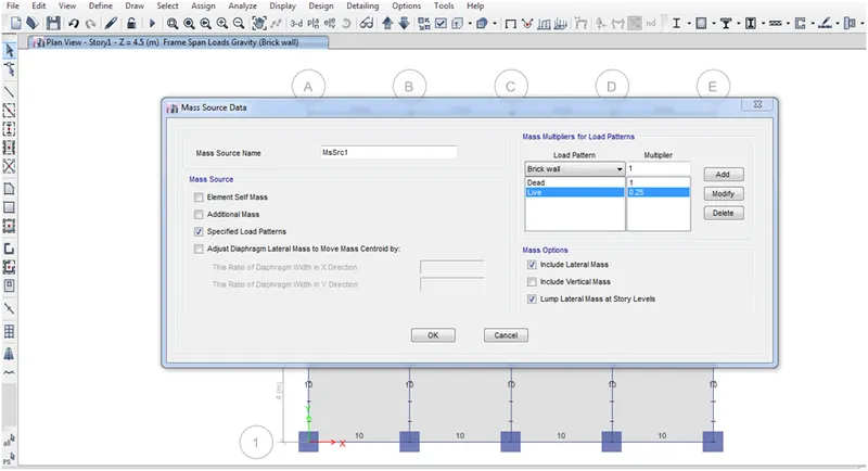
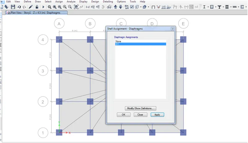
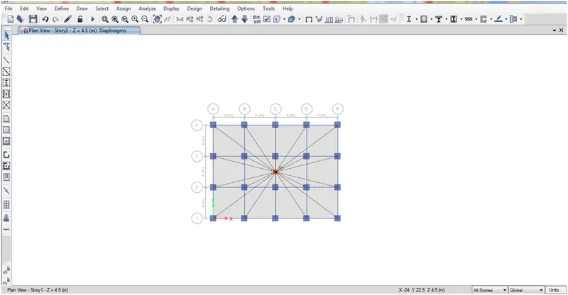
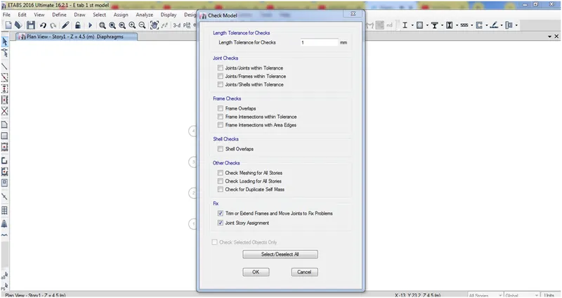
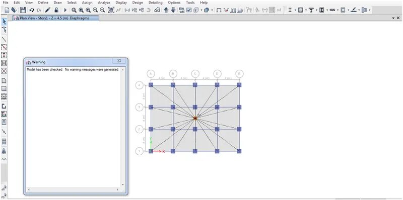
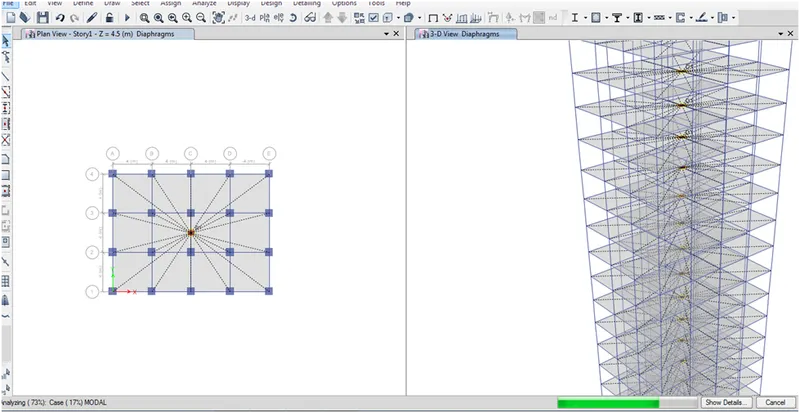
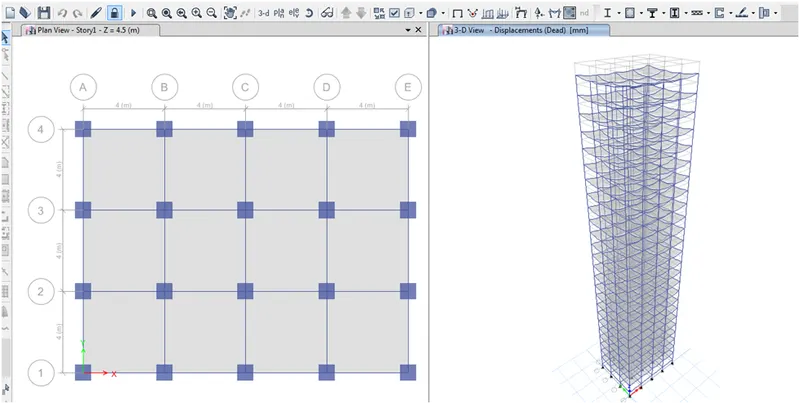
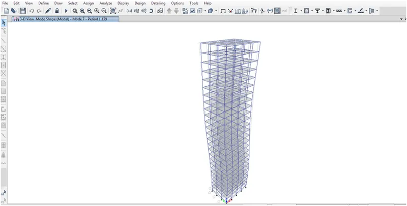
The animation play of the building behavior after the asign of load and the vibration of the building in annimation