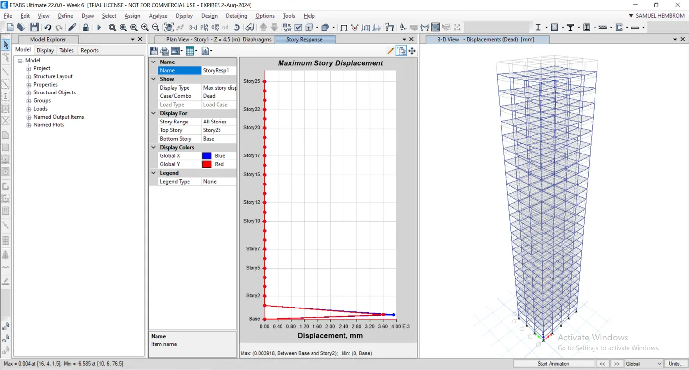
Modelling of 25 storey building with the specified properties using ETABS
- Given Data:-
Structural Element Sizes
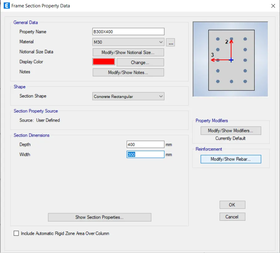
- Beams: 300 x 400 mm
- Columns: 800 x 800 mm
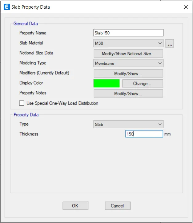
- Slab: 150mm thick
Material Properties:
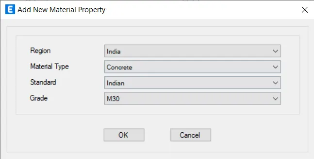
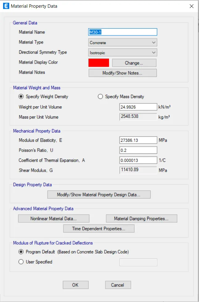
- Grade of Concrete: M30
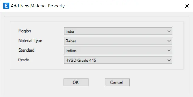
- Grade of steel Reinforcement bars: Fe415
Loading Details:-
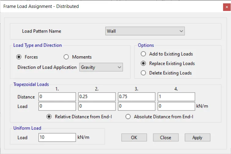
- Dead Load on beams from infill wall: 10kN/m (Let us assume the same for floor in view of parapet).
- Live load on floor: 3kN/m^2 (Let us assume same for roof floor)
- Buildings are assumed to be pinned at the base.
- All columns in all story are of the same size.
- All beams in all storeys are of the same size.
- Building is located on Soil type-II and in Zone-III. Assume other factors if required.
Aim:-
To model a 25-storey building using ETABS software and verify the seismic code requirement from ETABS analysis.
Procedure:-
- Open ETABS software.
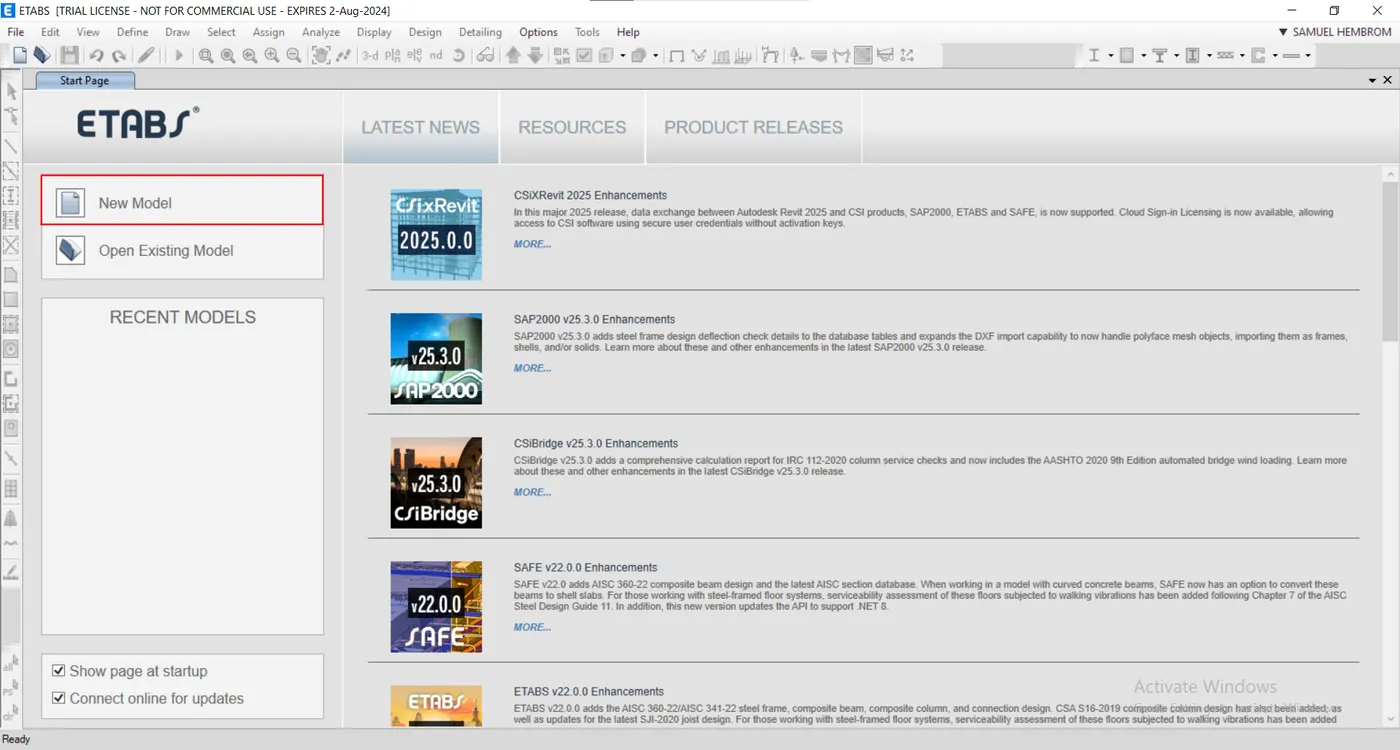
- Click New Model.
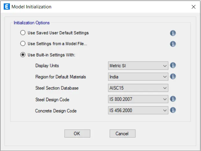
- Give model initialization setting as follows.
- Click OK.
- In the new model quick template dialogue box, select custom grid spacing and click Edit grid data.
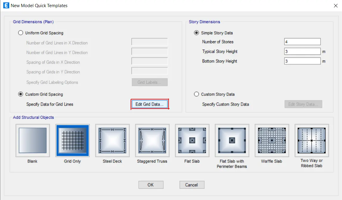
- Give the following settings in grid system data dialog box.
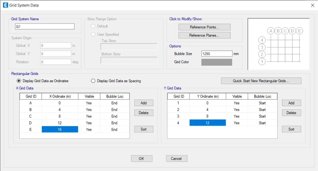
- Click ok.
- Select custom story data under story dimension and click edit story data.
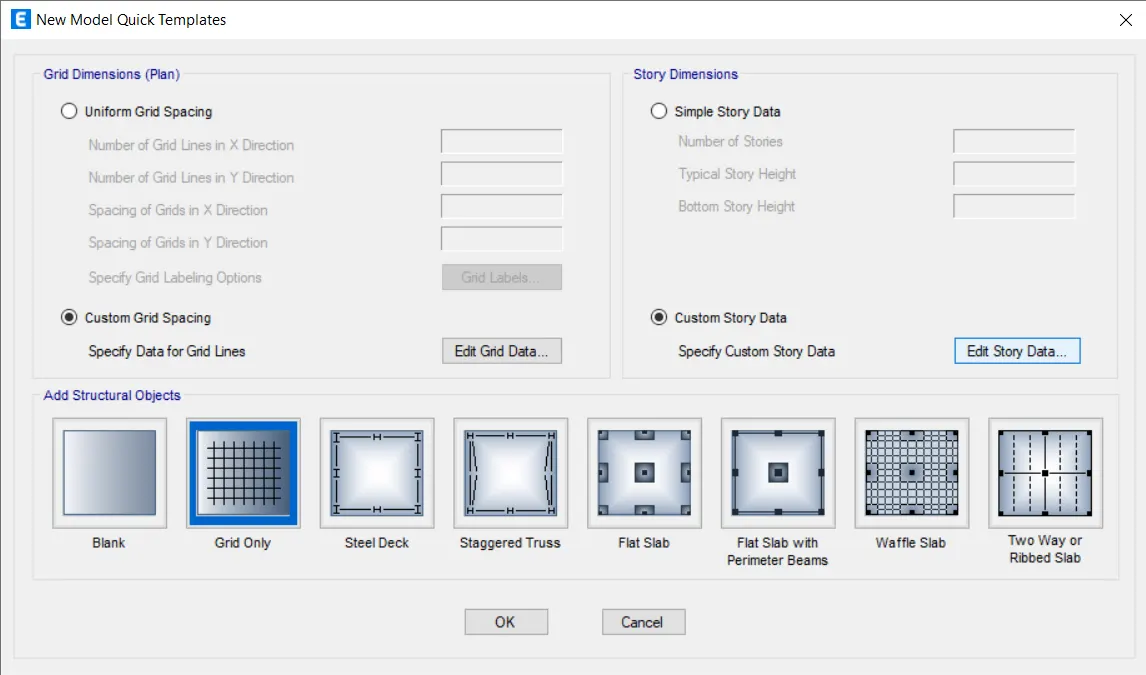
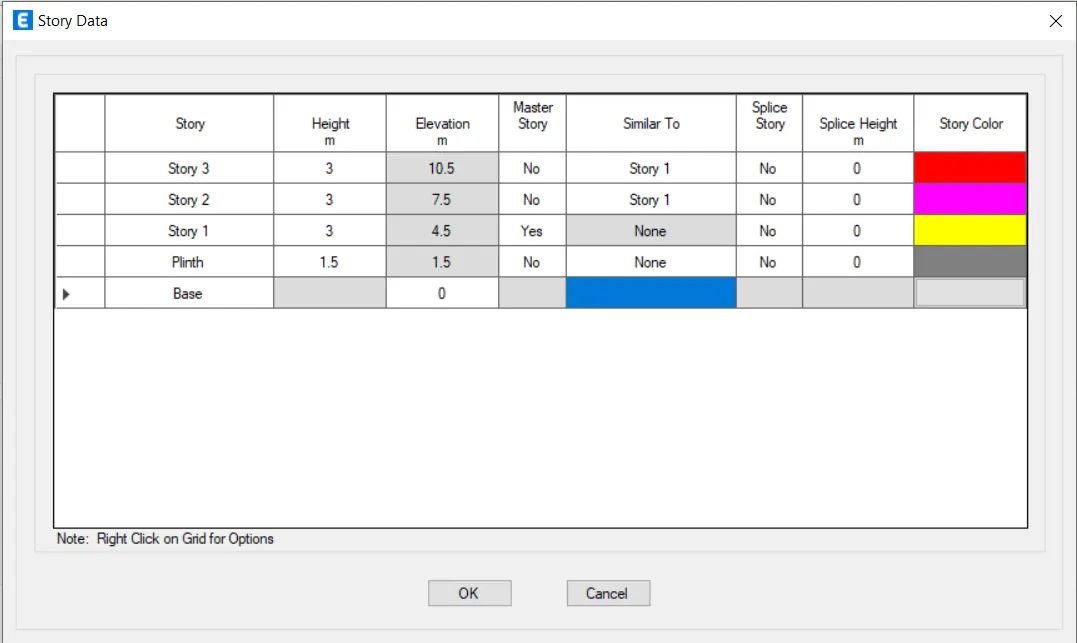
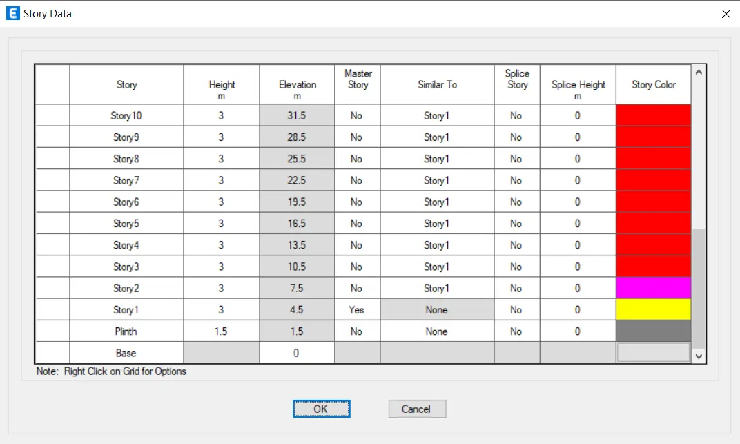
- Give the story data for first-three story as follow having story 1 as master story.
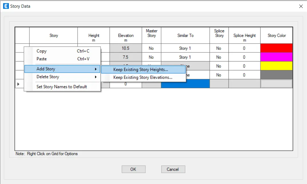
- Write click on the first column and select add story and click keep existing story heights.
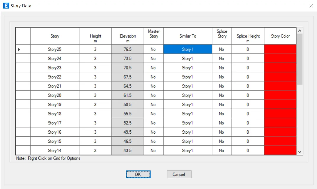
- Give number of added story as 22.
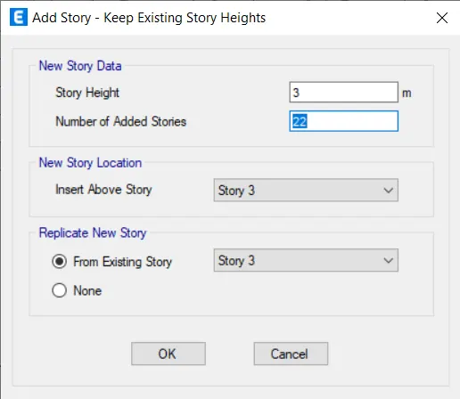
- Click Ok.
- Click Define -> Material properties.
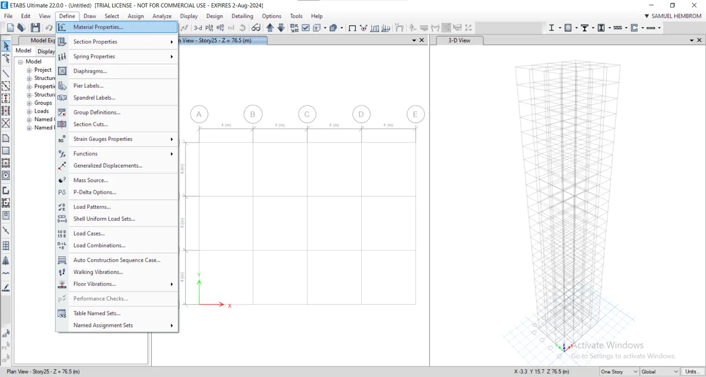
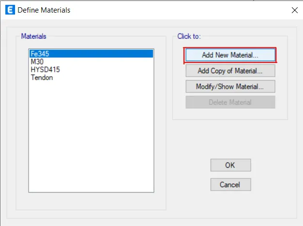
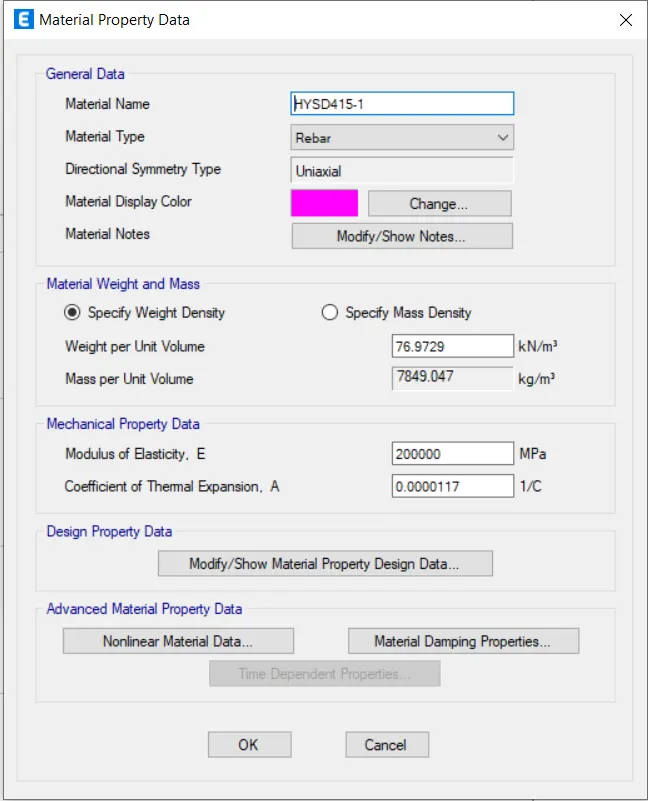
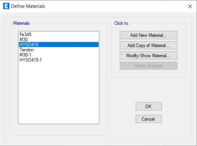
- Select Add new material in the dialog box concrete and reinforcements as shown in image below.
- Select the concrete shape as rectangular and give the following settings for the Beam.
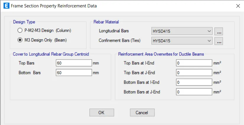
- Click on Modify/ Show Modifiers.
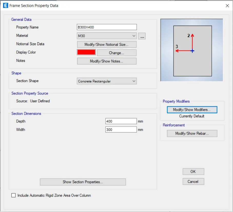
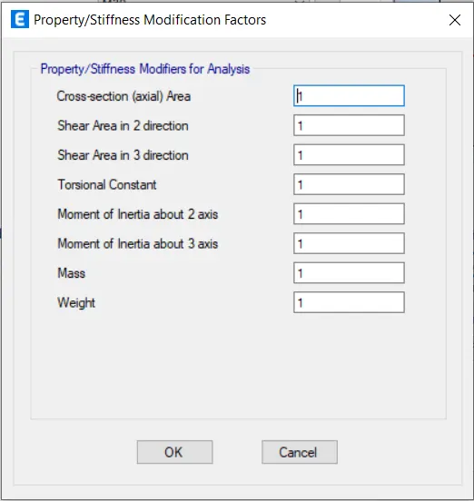
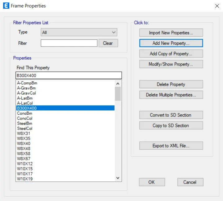
- Repeat the same for columns with the parameters given in the question.
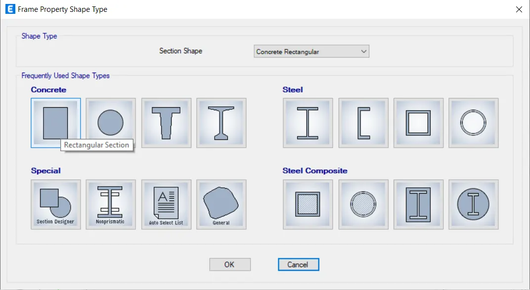
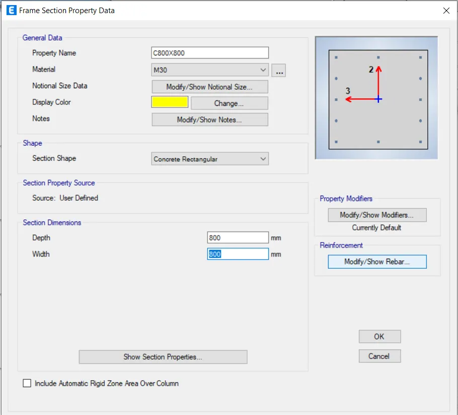
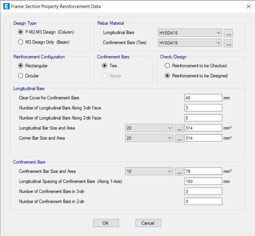
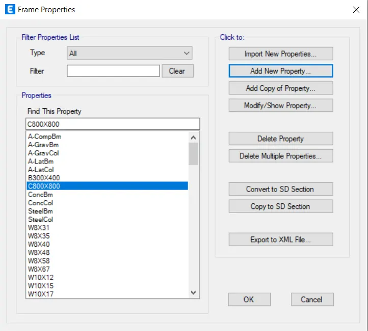
- Column property is added.
- Click -> Section Properties -> Slab Section.
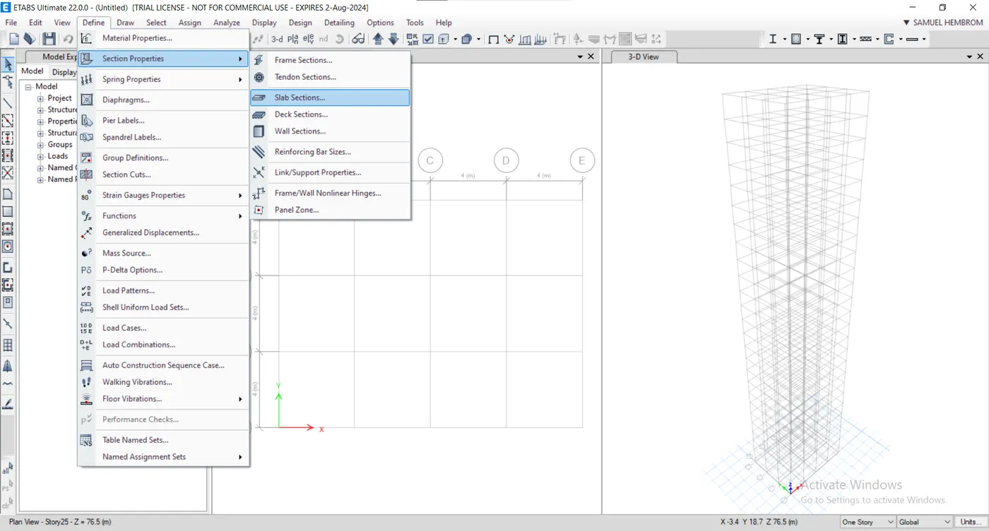
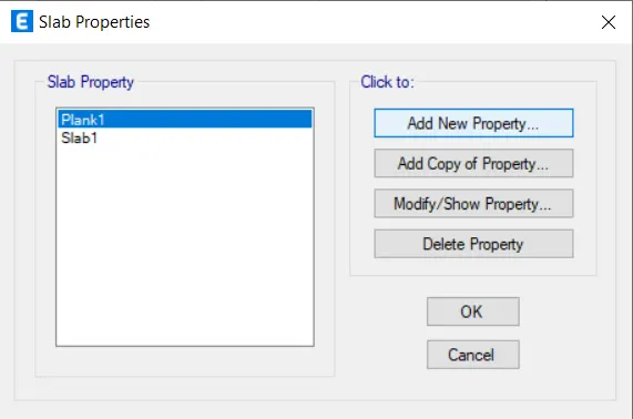
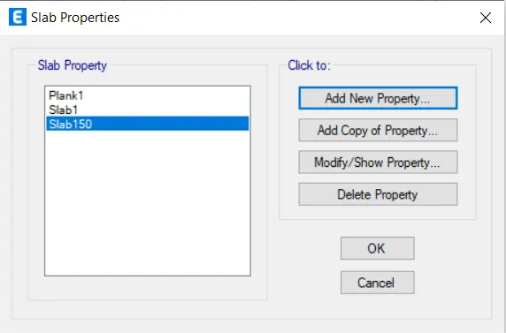
- Select Add New Property and give the following settings.
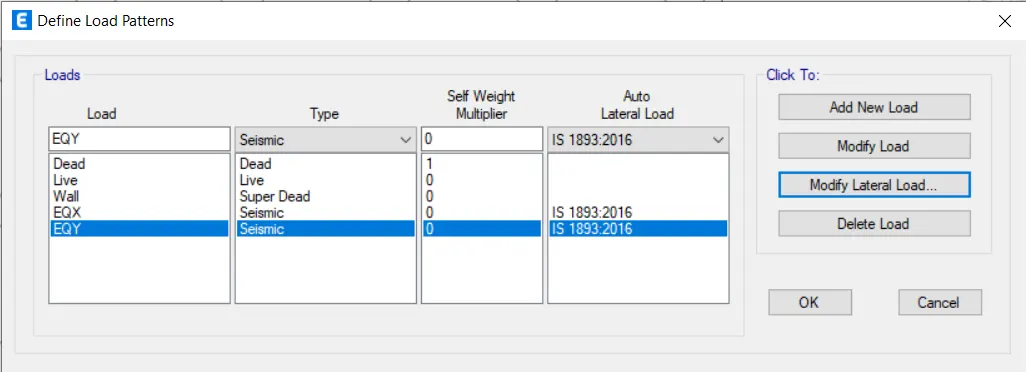
- Click Define -> Load Patterns.
- Define Load Patterns by its name.
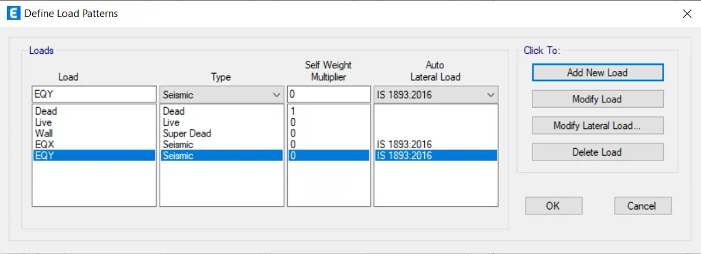
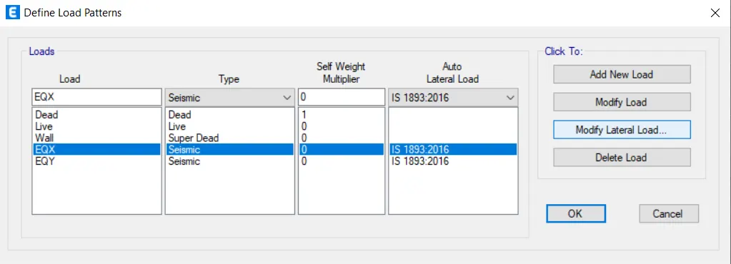
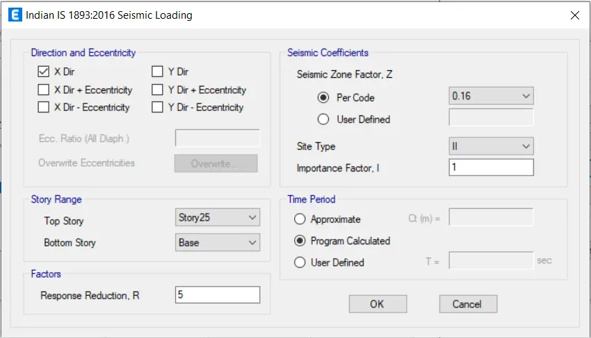
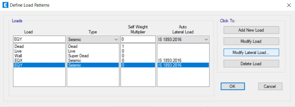
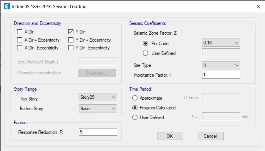
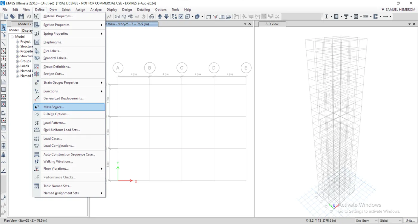
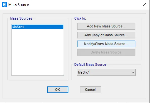
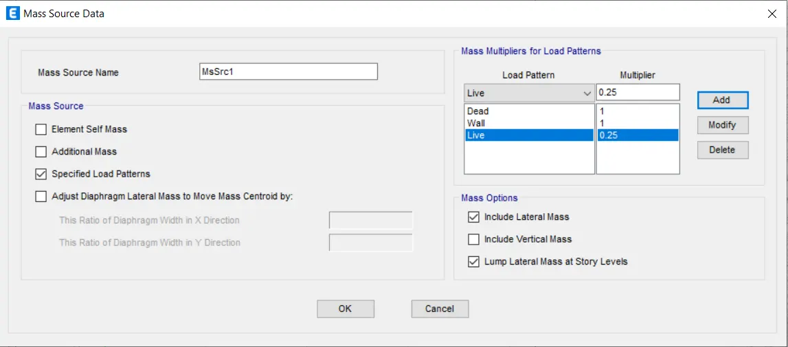
- Click Define -> Mass Source
- Check load cases by click Define -> Load Cases.
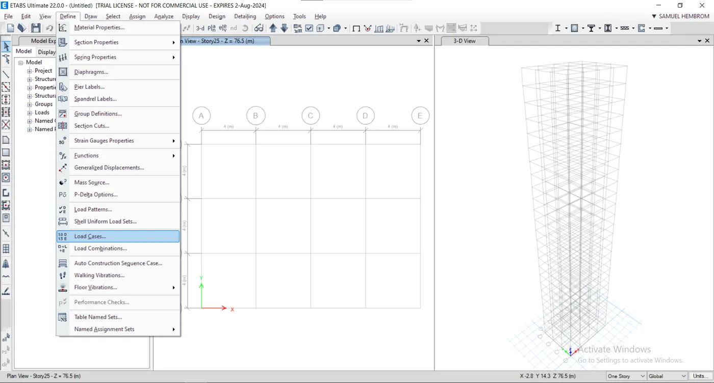
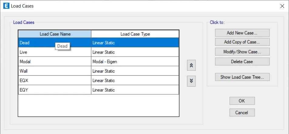
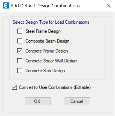
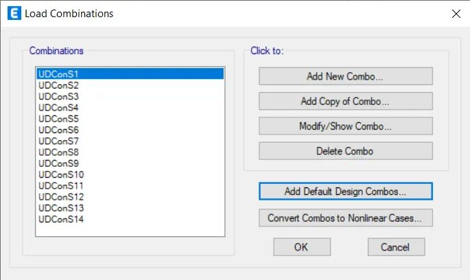
- Create Load Combination, Define -> Load Combinations.
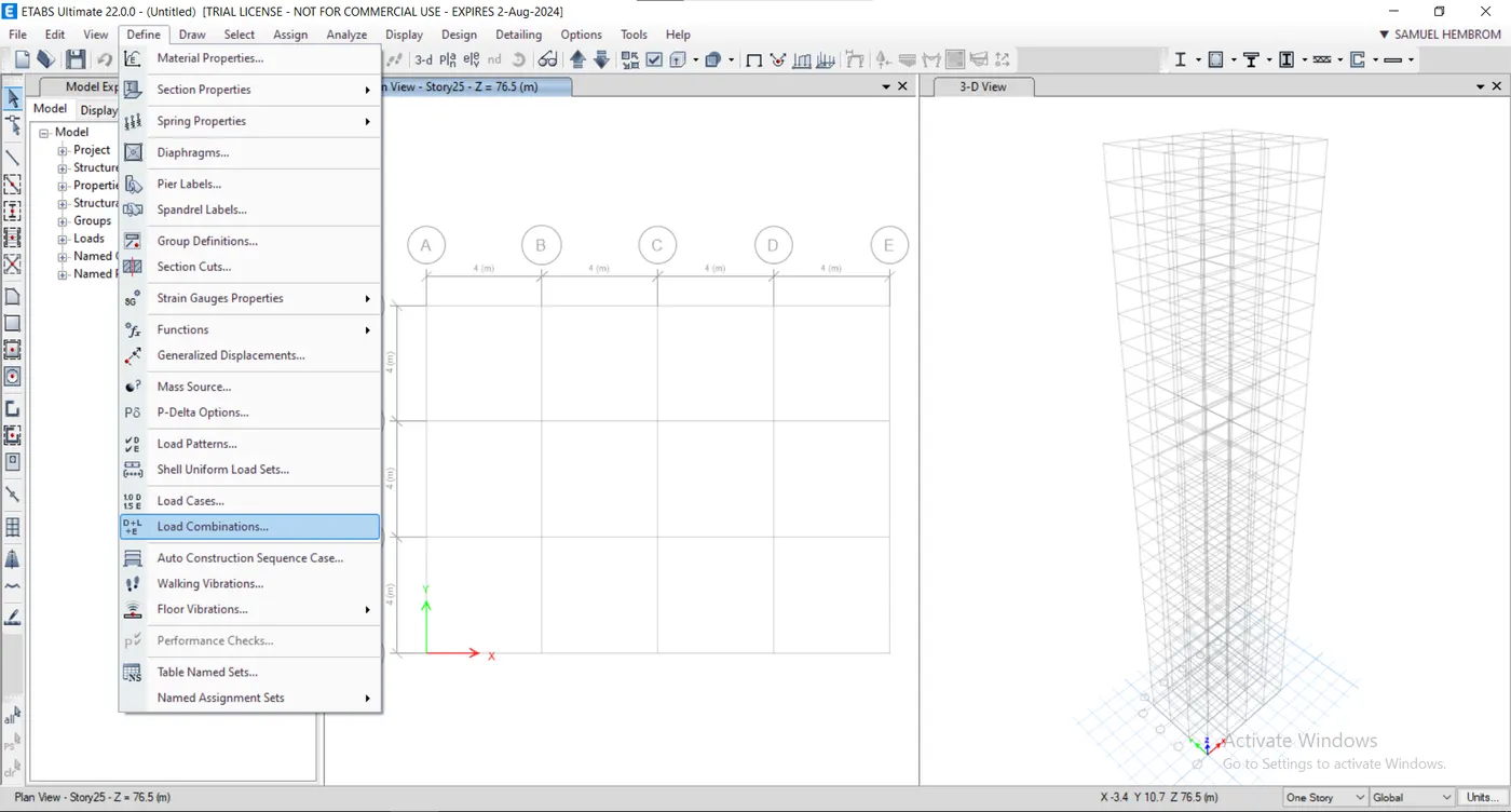
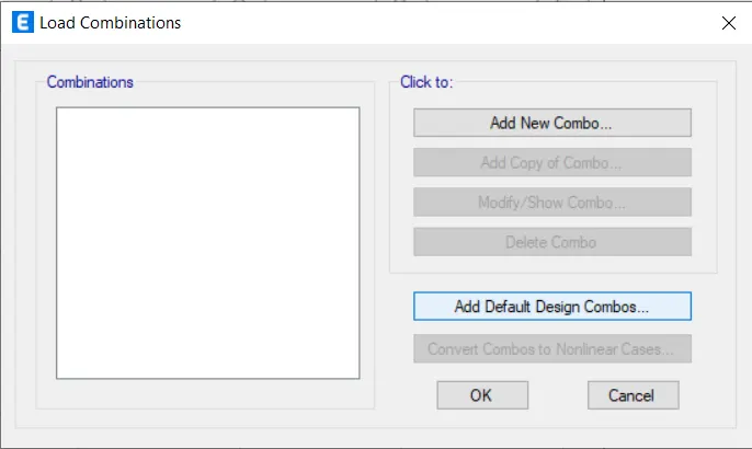
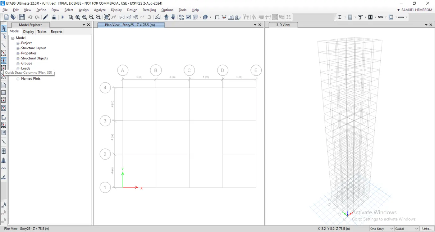
- Create Columns using "Quick Draw Column" tool.
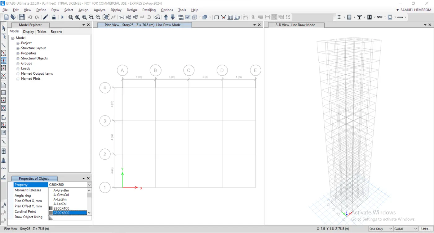
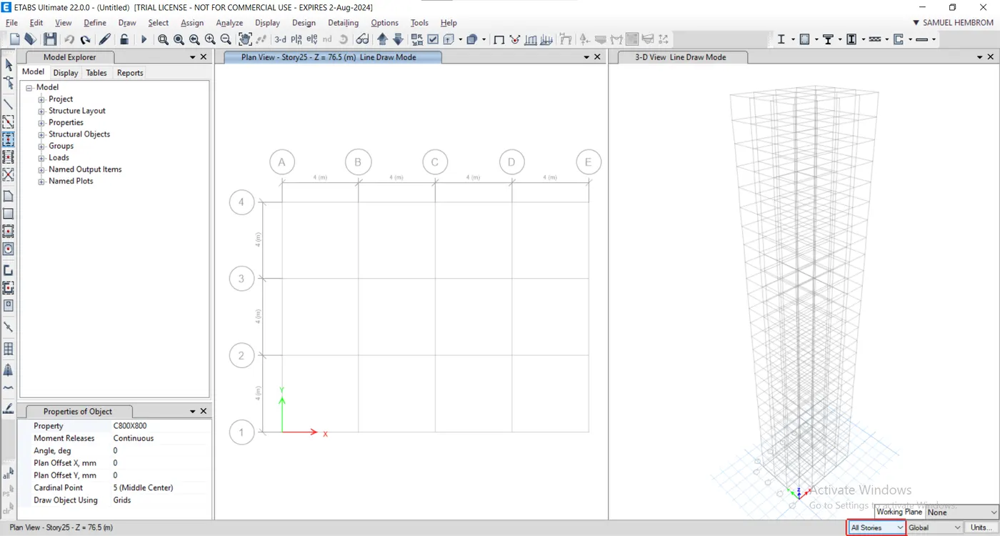
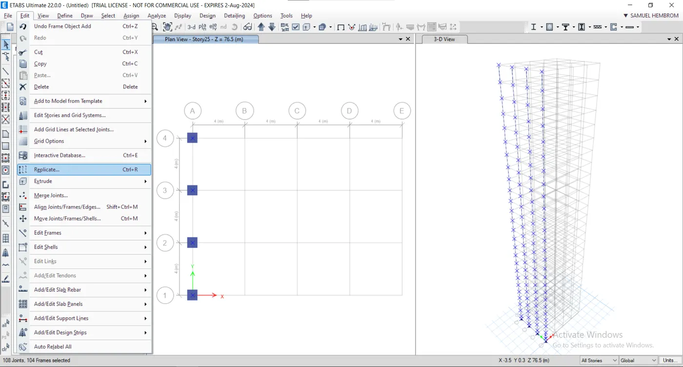
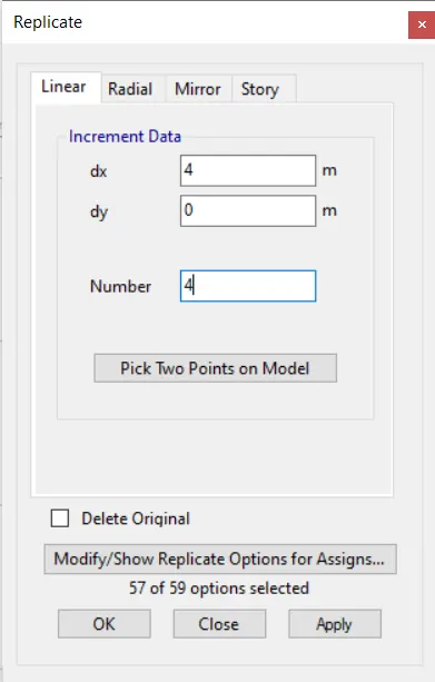
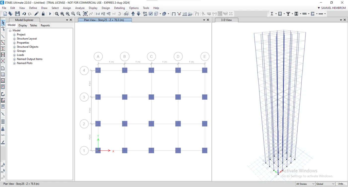
- Select "Quick Draw Beam" tool.
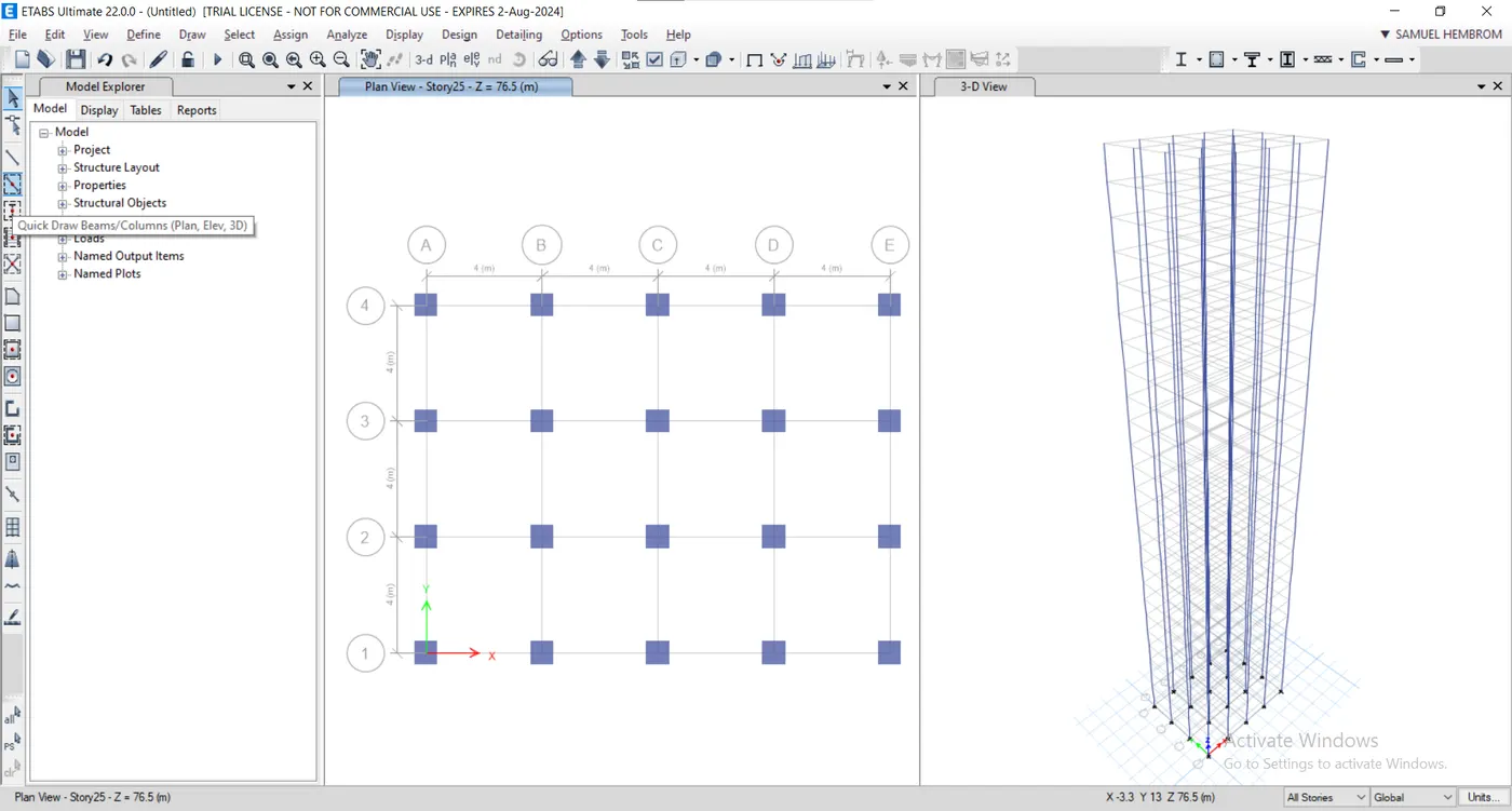
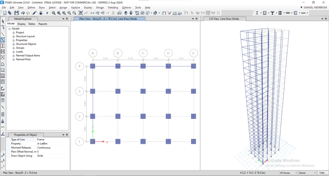
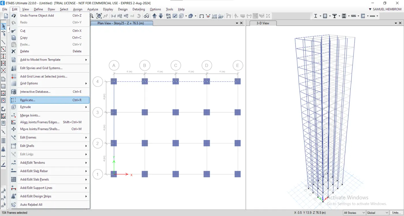
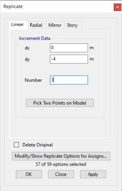
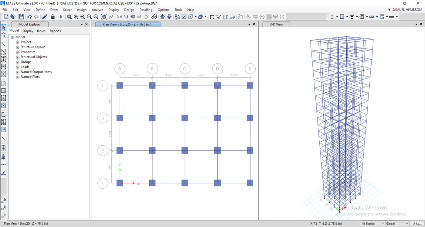
- Select First Floor in Plan View.
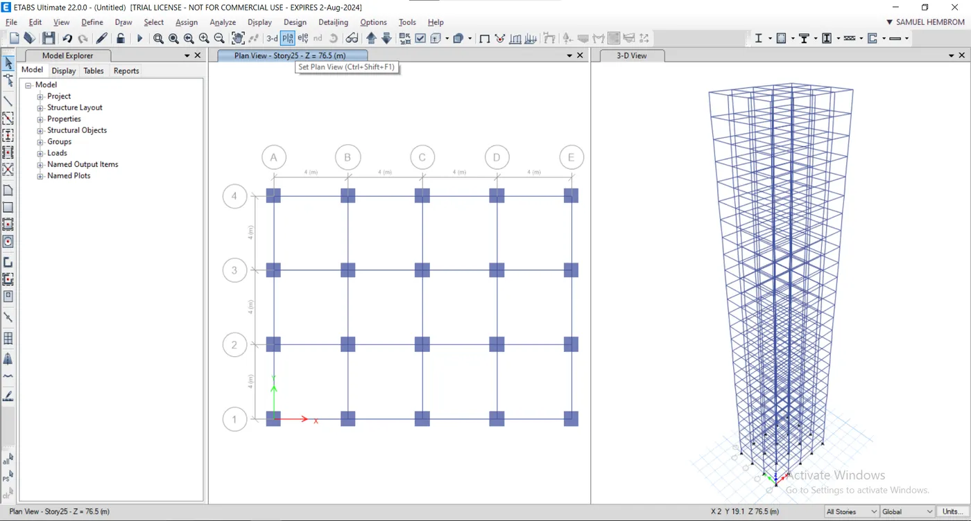
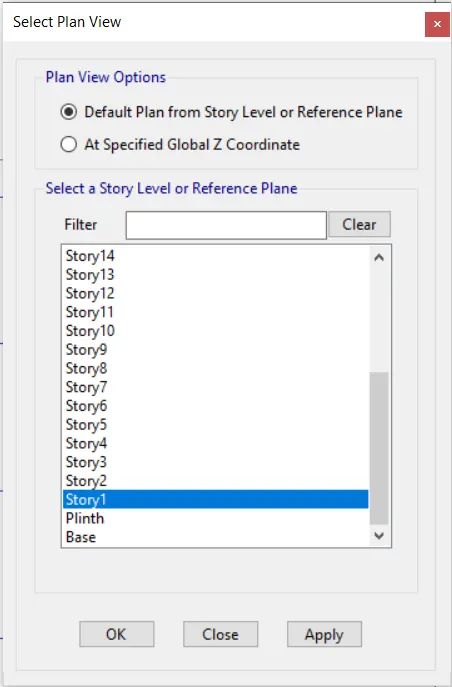
- Draw slab using quick slab by having similar stories in the status.
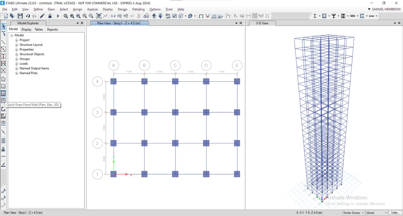
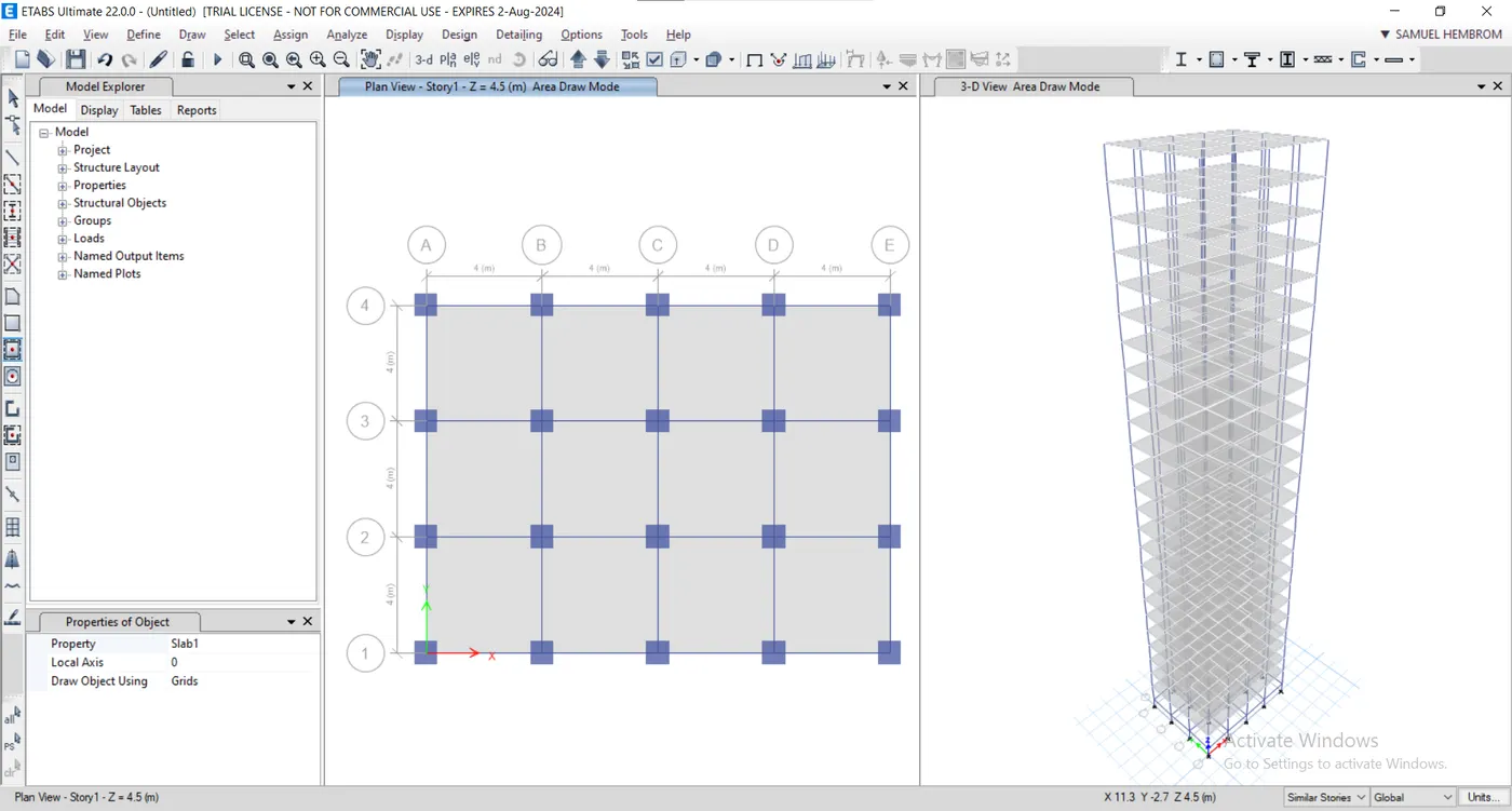
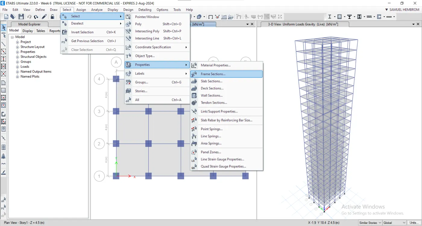
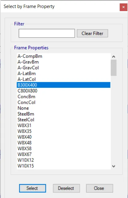
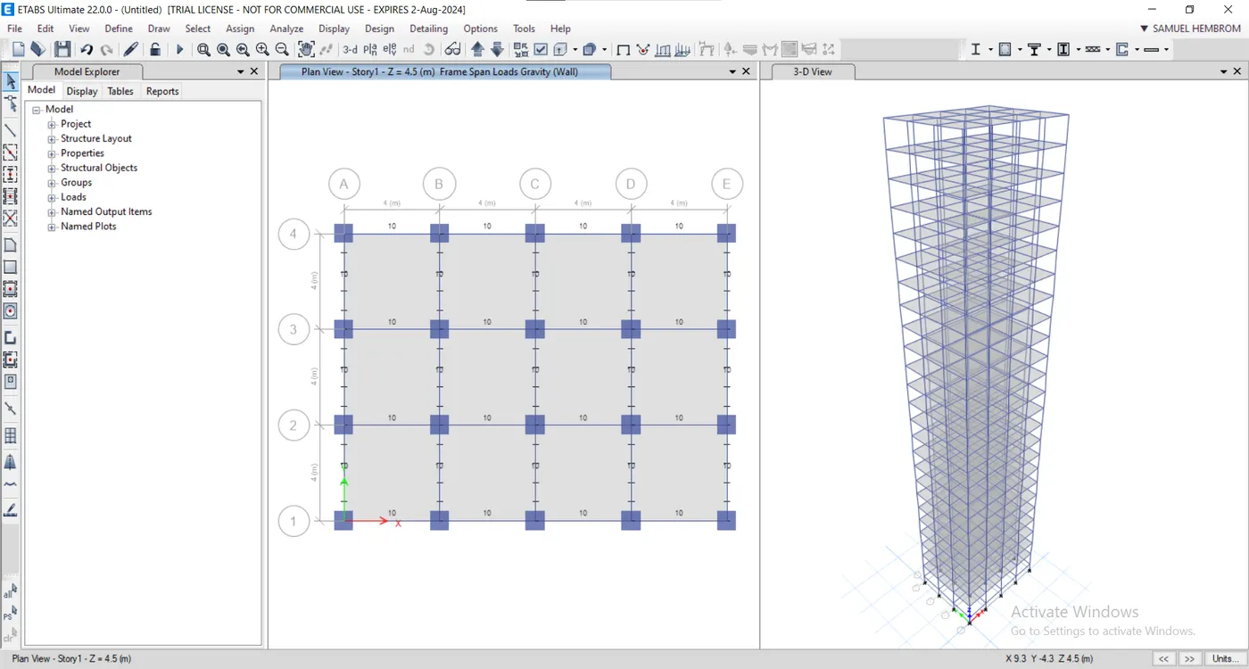
- Select all the beams from select tab.
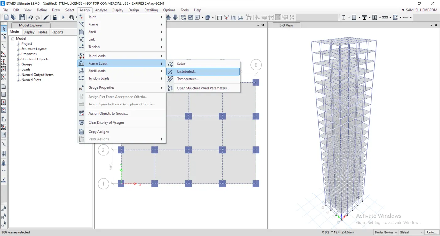
- Assign frame loads as distributed from assign tab.
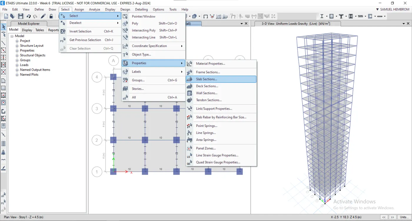
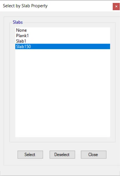
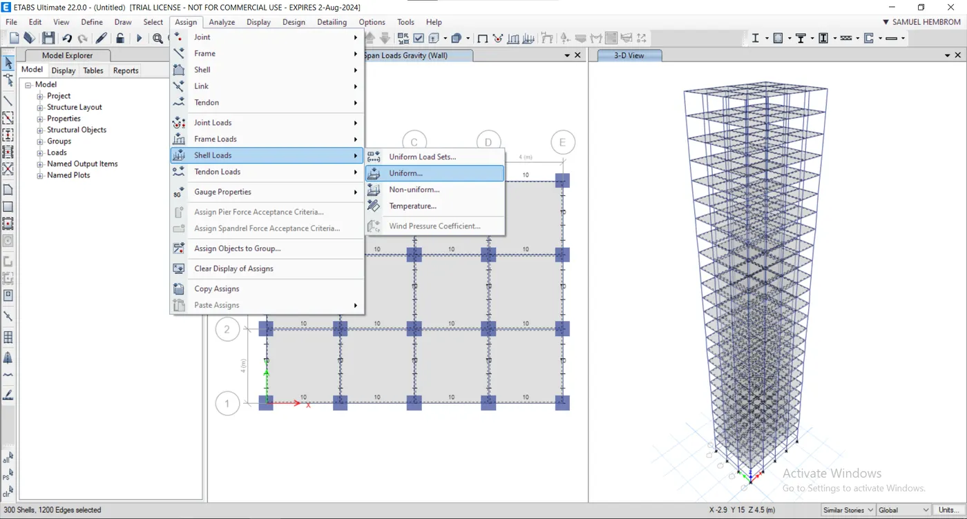
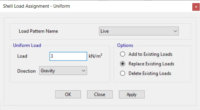
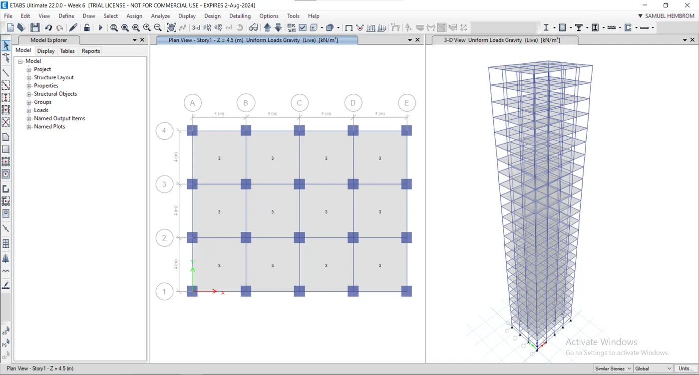
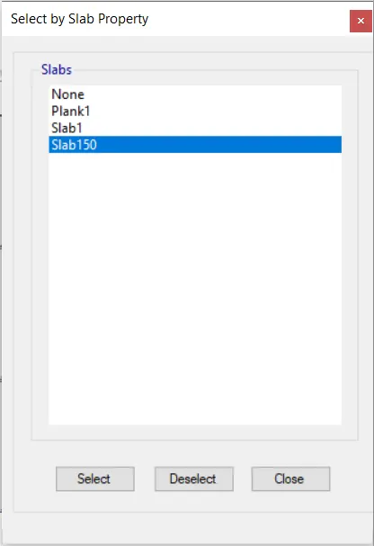
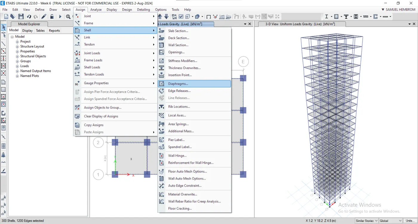
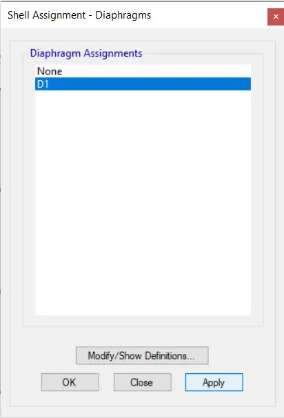
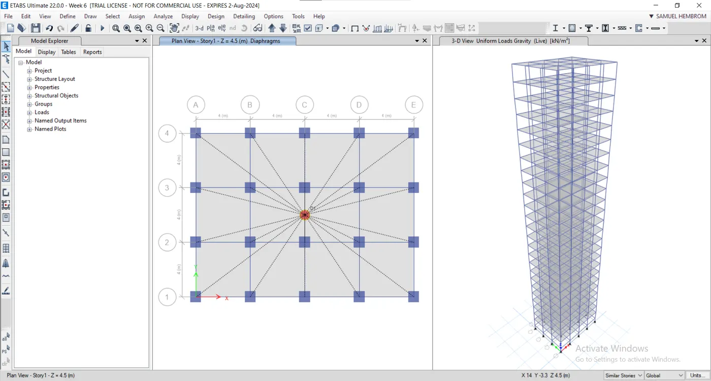
- Select the slabs from select tab and assign as diaphragm from assign tab.
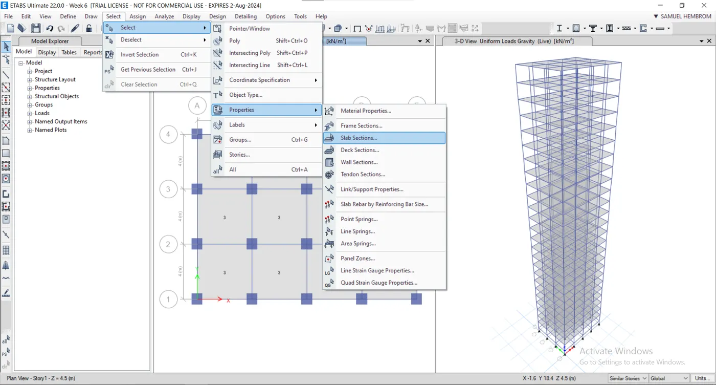
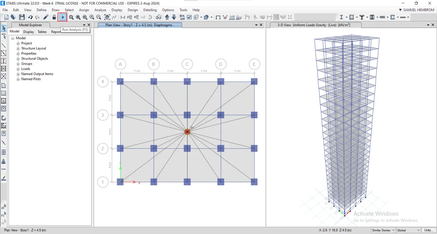
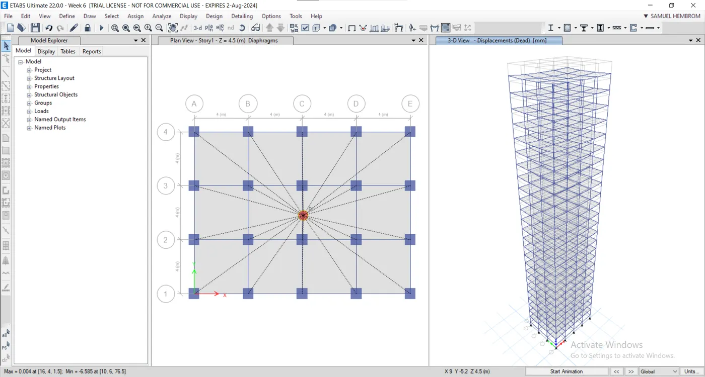
- Click run analysis in the panel after saving the file.
Result:-
| Criteria | Desirable Solution | Exercise Result | |
|---|---|---|---|
| Fundamental translation natural period | X - Direction | 4.4 Seconds | 4.41 |
| Y - Direction | 4.2 Seconds | 4.22 | |
| Torsional Irregularity | IS 1893-2016(Part - I) Table - 5 | Torsional mode time period should be lesser than X and Y direction time periods | Yes |
| Vertically Irregularity | IS 1893-2016(Part - I) Table - 7 Clause - 7 | First three modes together should contribute at least 65% in mass participation factor in each principal direction | Yes |
| Fundamental lateral natural periods in two principal plane directions away from each other by at least 10%. | |||
| Inter-Storey drift | IS 1893-2016(Part - I) clause - 7.11.1.1 | Storey drift shall not exceed 0.004 times the storey height for base shear with no load factor (4x10^-3) | Yes |
- Click Display -> Story response plot. Change the display type to maximum storey drift and desired combo to see the plots.