Modelling of 25 storey building with the specified properties using ETABS
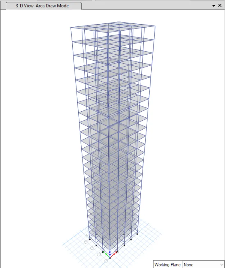
Aim: To Model a 25 storey building on ETABS with structural properties as specified. Ground floor or plinth floor level can be taken at a height of 1.5 metres from the base. Each of the successive 25 storeys has a storey height of 3 metres.
Introduction:
ETABS is an engineering software product that caters multi-story building analysis and design.Basic or advanced systems under static or dynamic conditions may be evaluated using ETABS. With a series of design and documentation platforms makes ETABS a coordinated and productive tool for designs.
Step 1:
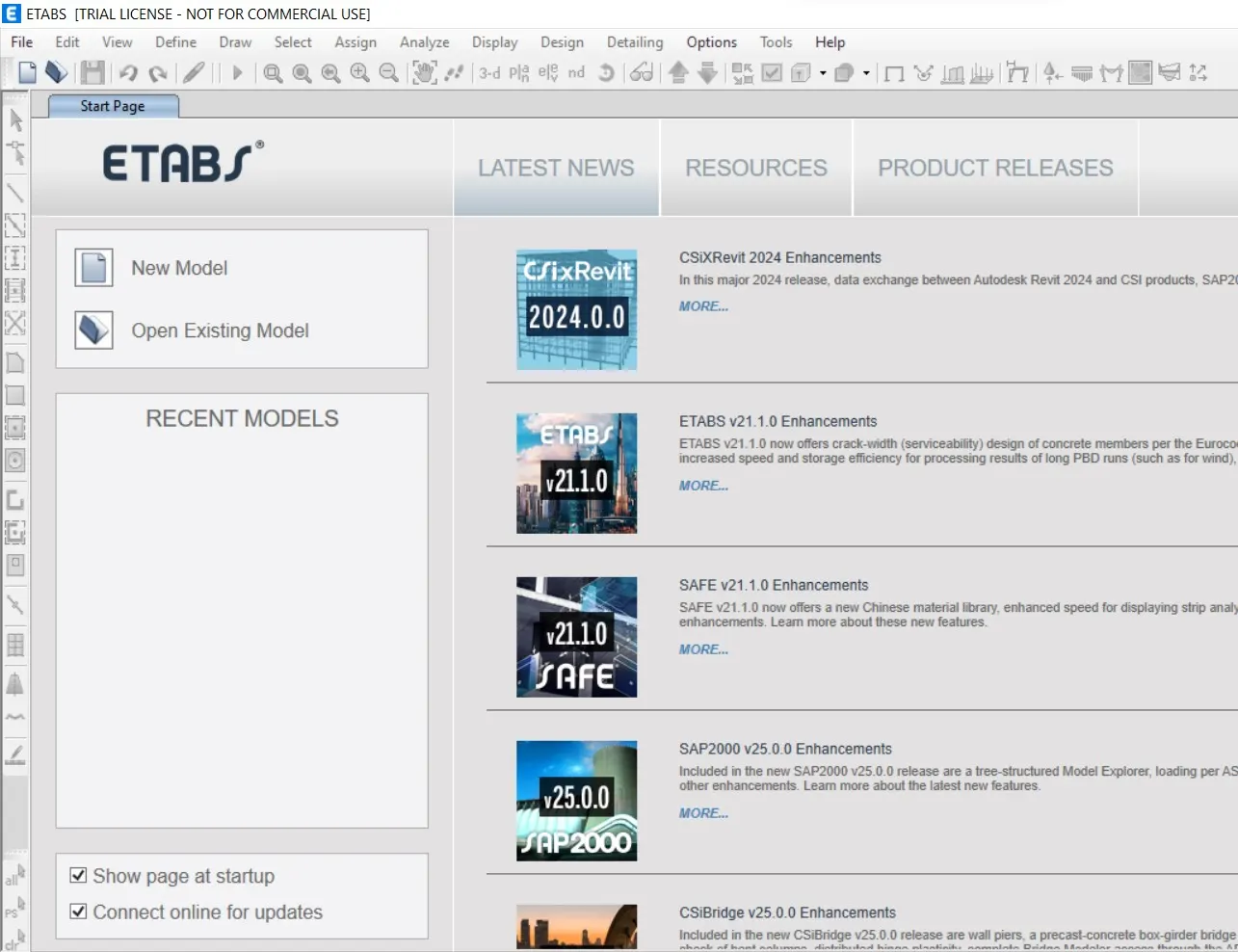
- Open the Etab software
- On the left side select the new model as shown below
Step 2 :
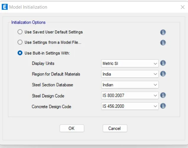
- Open the sofware Select the built-in settings with
- Check the display unit, steel design, steel design code, concrete design and then press OK.
Step 3:
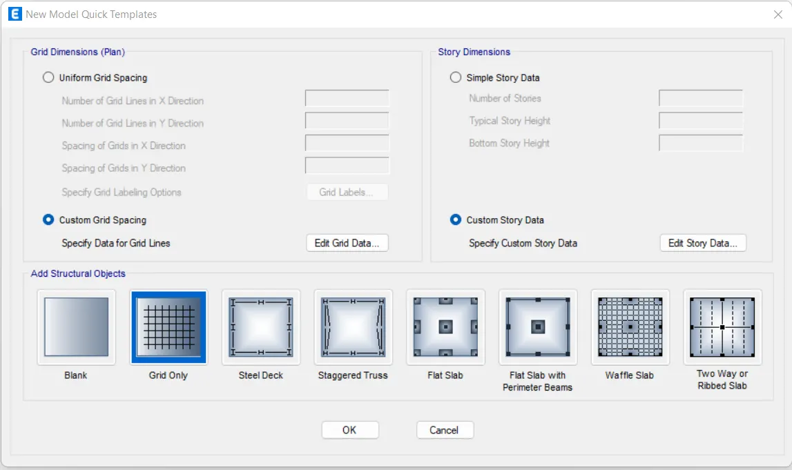
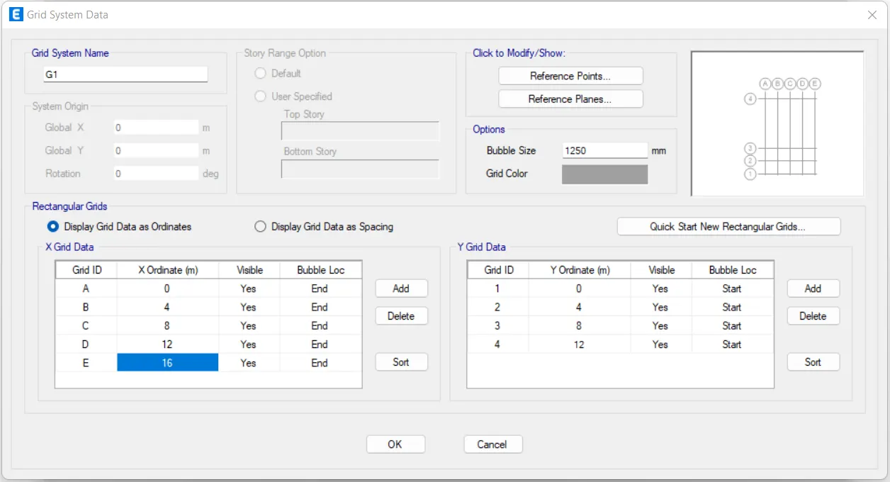
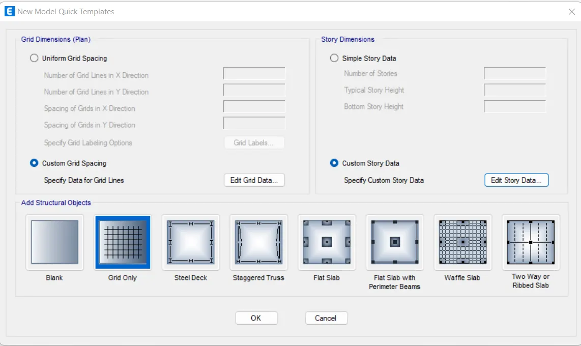
- The next dialog box shows the grid and storey system, select the custom grid selection, and select the edit grid option.
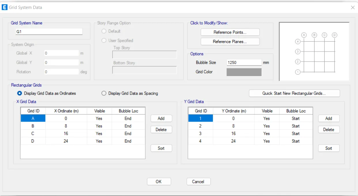
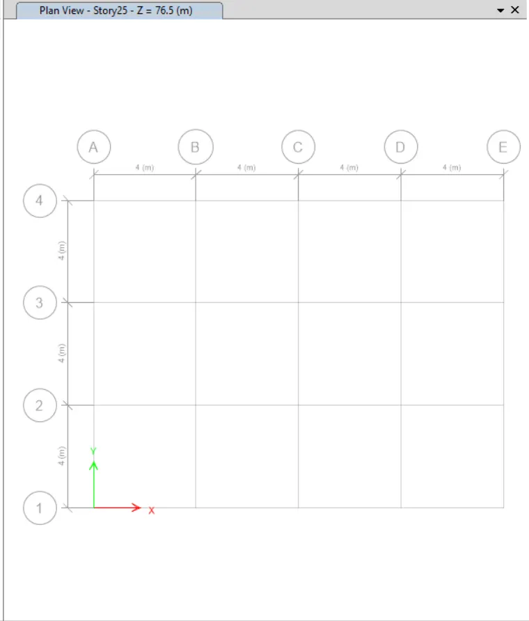
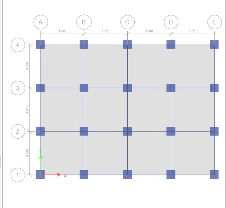
- As per the given dimesions in the question, enter 5 grid on X axis and 4 grids on the Y axis, with the spacing of 4 meter.
- Now the grids are set.
Step 4:
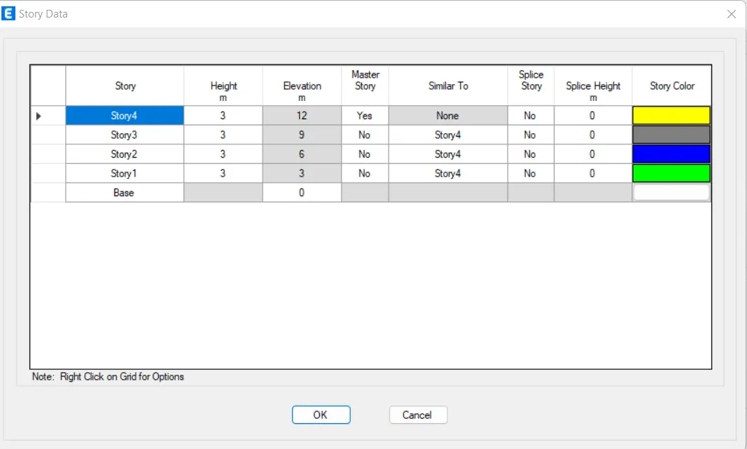
- Now select the custom storey option and edit the storey option.
- Now the plinth height should be given as 1.5m.
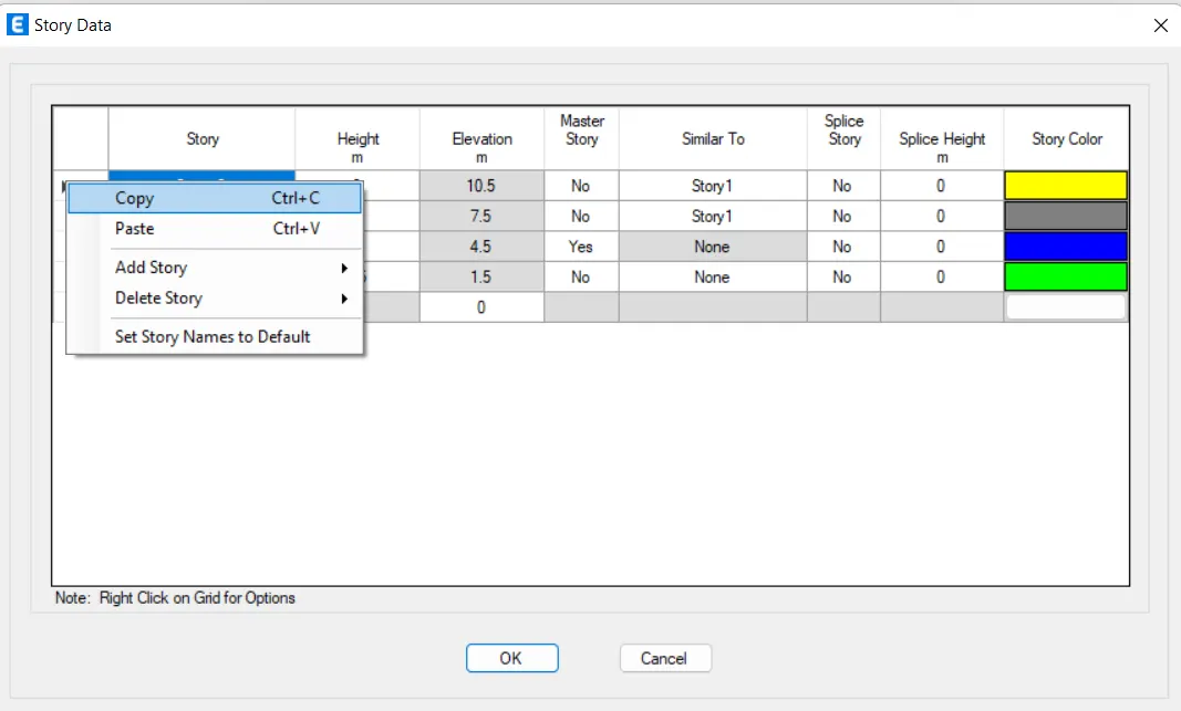
- Now right click on the left side of the plinth text, it pops a option which shows add story option, select that > new dialog box opens
- Fill the no of story as 25, and the height of story as 3m.
Step 5:
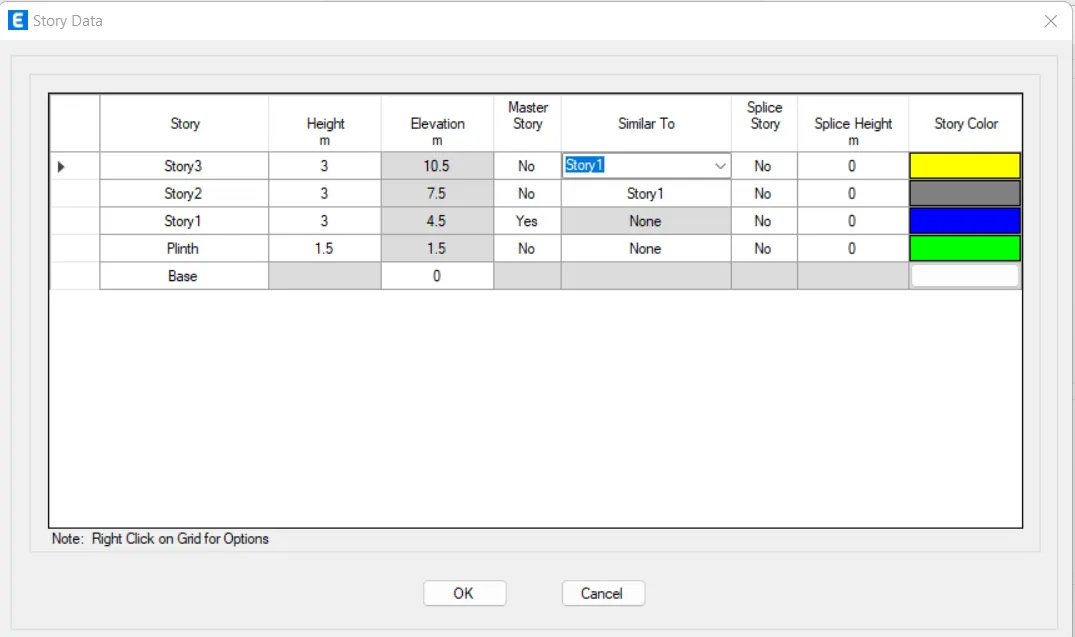
- From the add story option select the story height and add storys how many required and the storey height also should be maintained
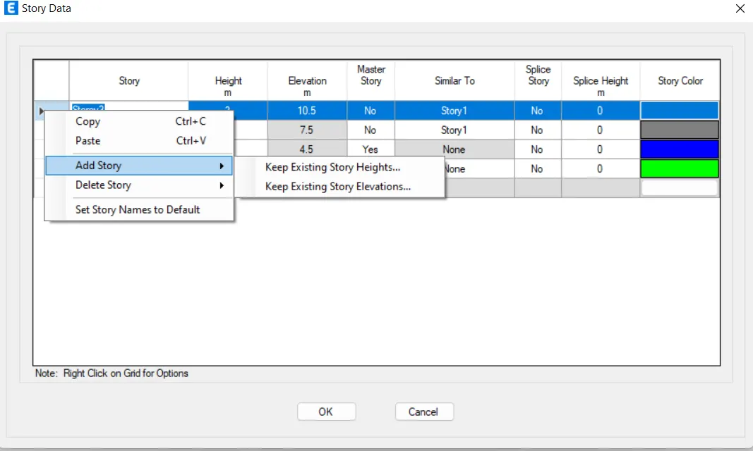
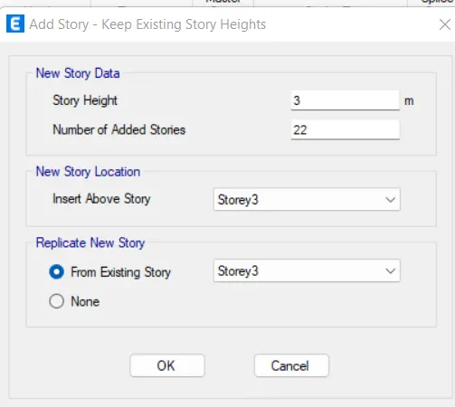
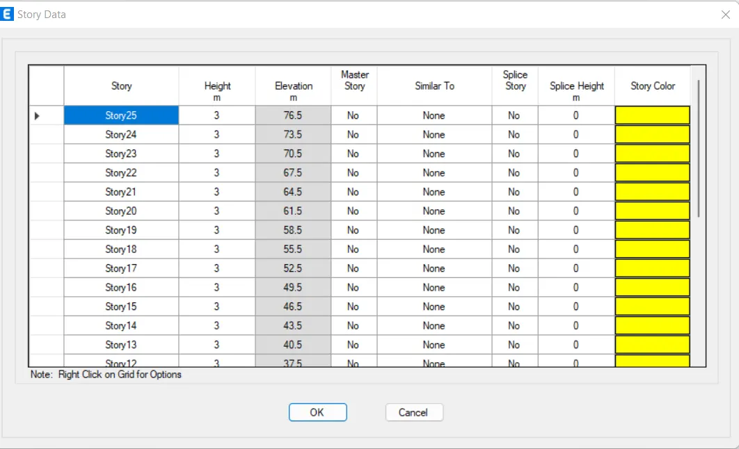
Step 6 :
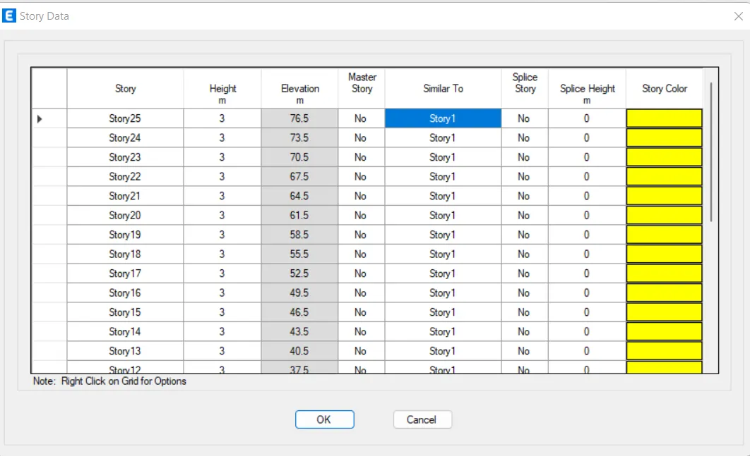
- Change name in similar to option as Story 1 in all the levels
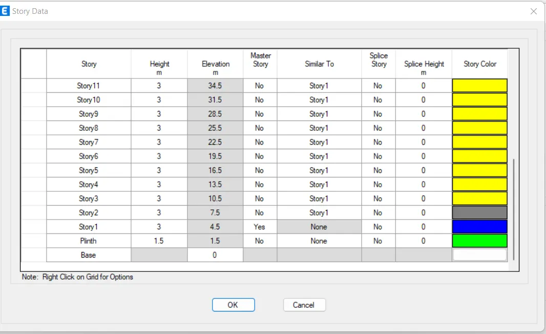
STep 7:
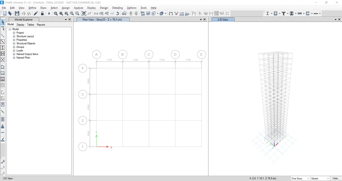
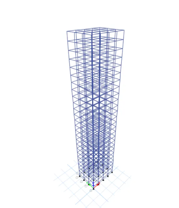
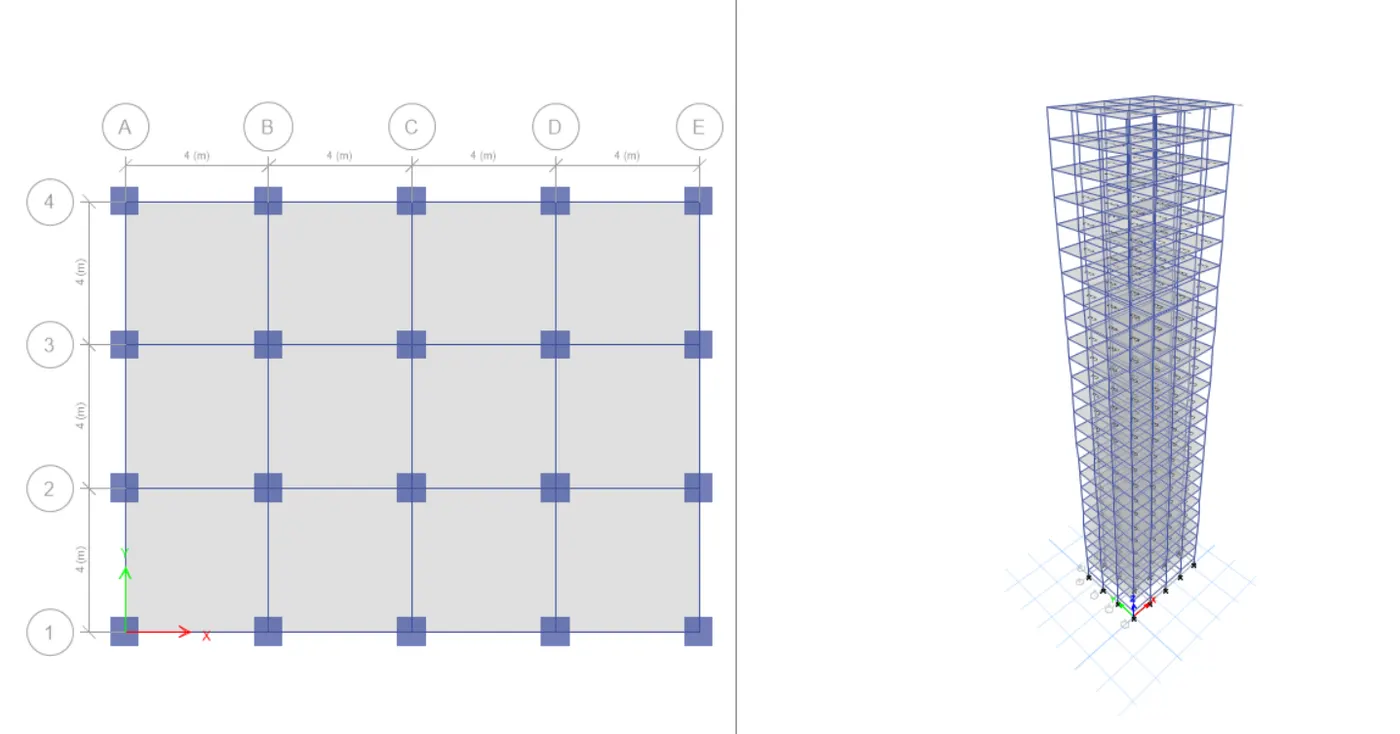
- From below we can see the grids and story are created
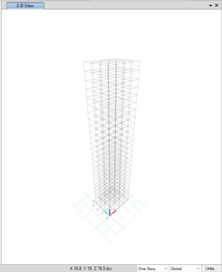
- 3d view and plan view is shown below'
Step 8:
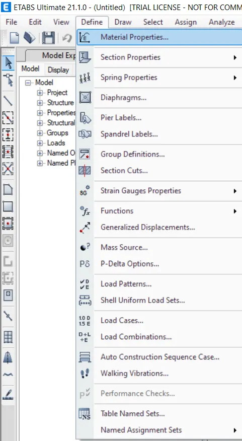
- Now select define > material property> new dialog box appears
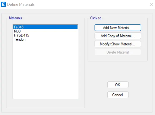
- Select Add new material option.
- That take us to the new dialog box, assign the codal as INDIAN, grade as m30, material as Concrete
Step 9:
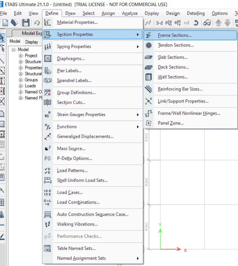
- Next go the define option and select the section properties and go to the frame section
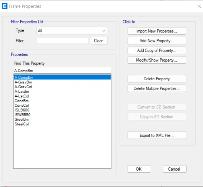
- Select the concrete rectangle and click ok
- And set the material name as (B300 X 400) and material "M30"
- Go to the modify show rebar
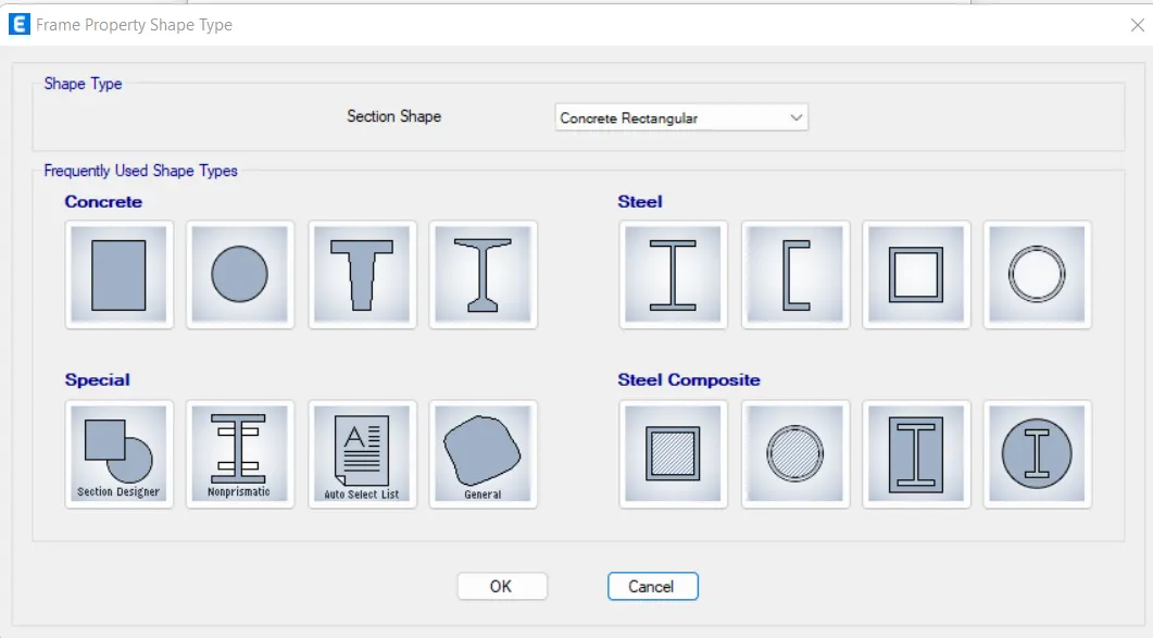
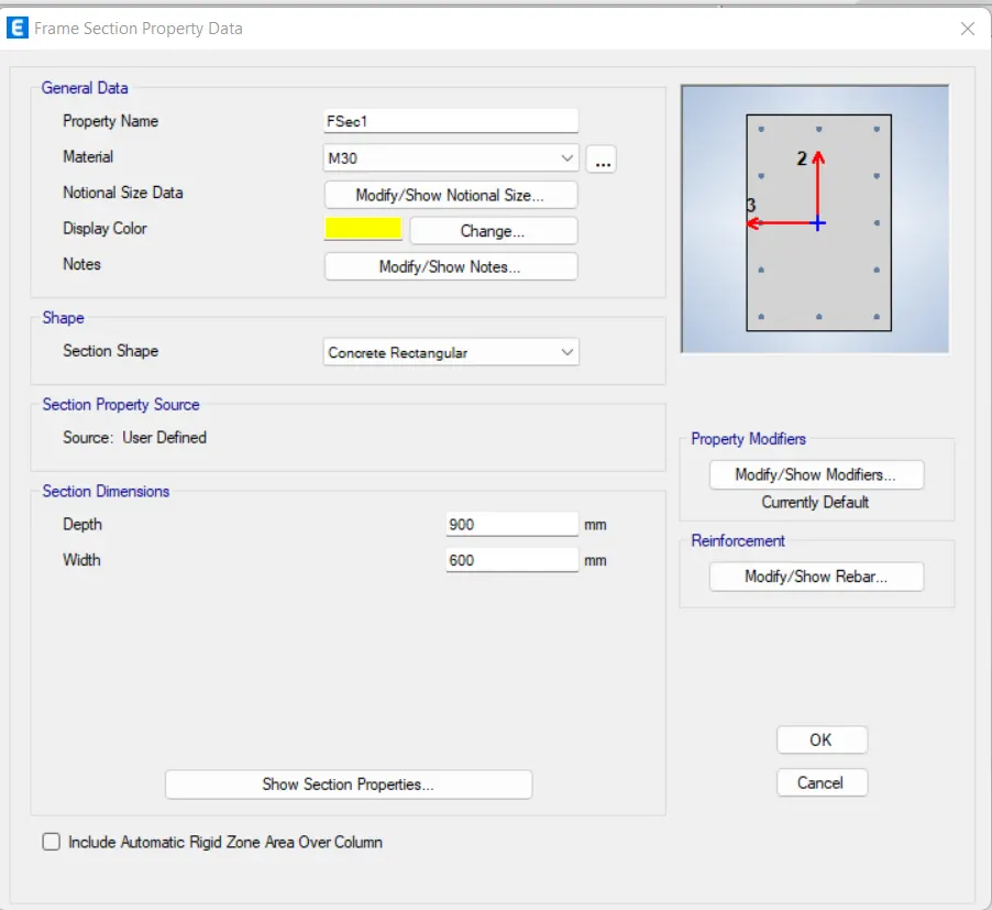
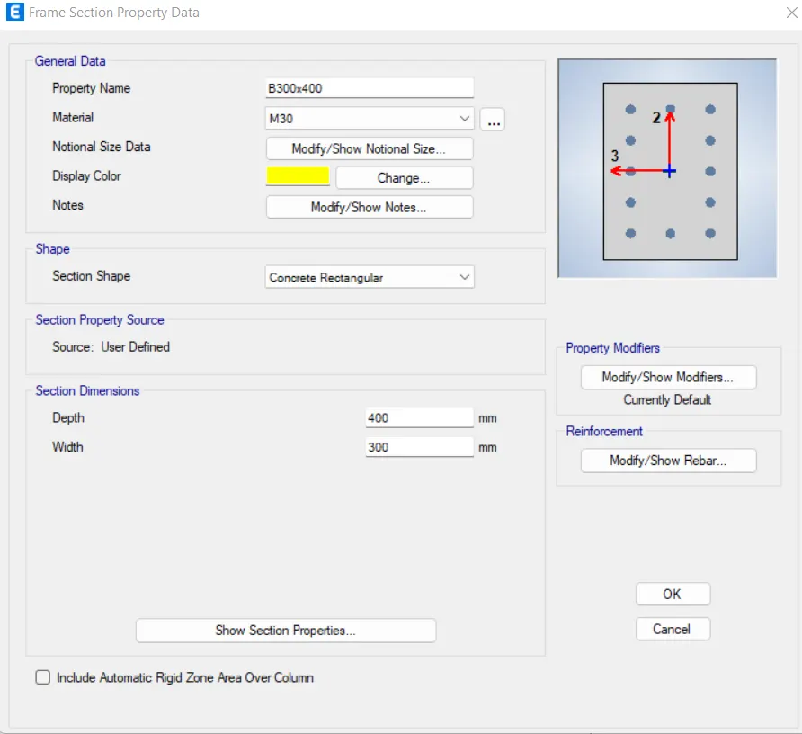
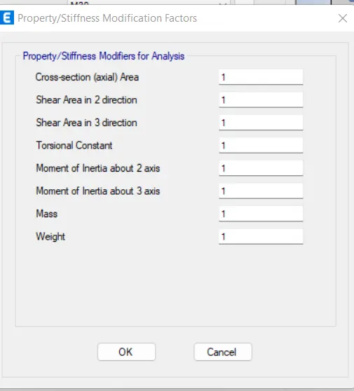
- And set the design type M3 beam and give the rebar material as HYSD 415 for both
- And then click ok
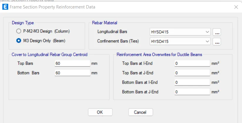
Step 10 :
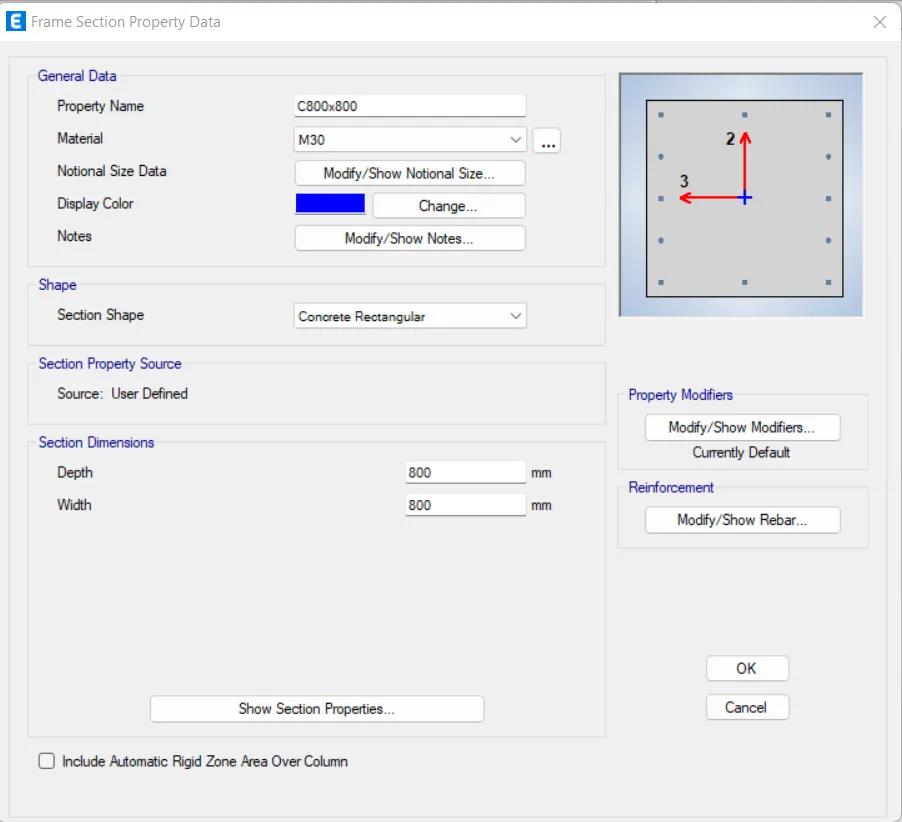
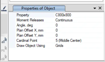
- Next we can open the same concrete rectangle and select the column in here
- And set the material name as (C800 X 800) and material "M30"
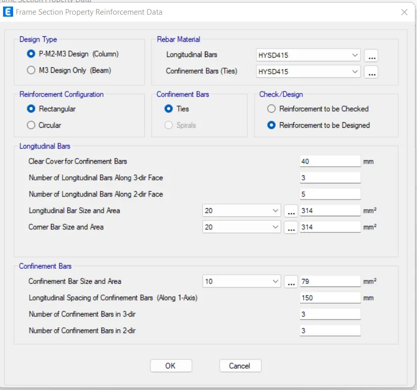
- Go to the modify show rebar
- And set the rebar as HYSD415 for both
- Finally click ok
Step 11:
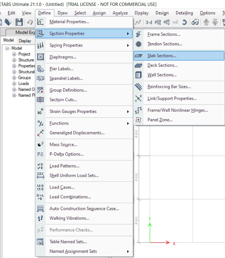
- Go to the define tab and select the section properties and then select the slab section
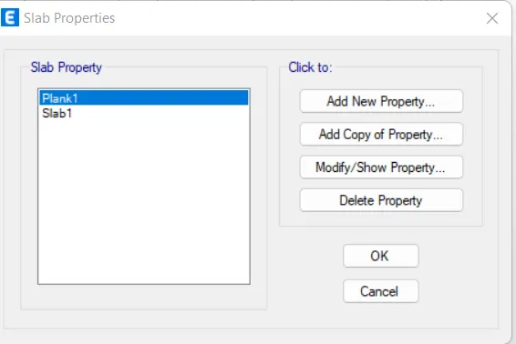
- Then open a slab properties box
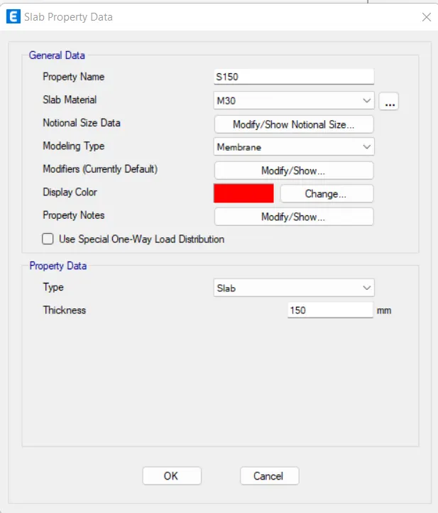
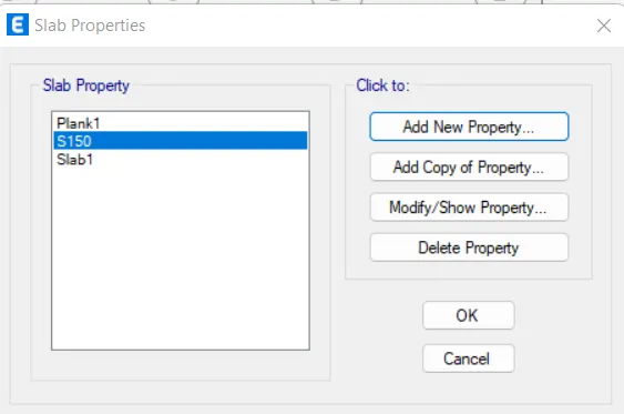
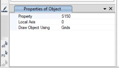
- Click modify option and then set properties name "slab 150"
- Give the slab material " M30"And modeling type " membrane"
- Give the thickness of slab as 150mm and Finally click ok
Step 11:
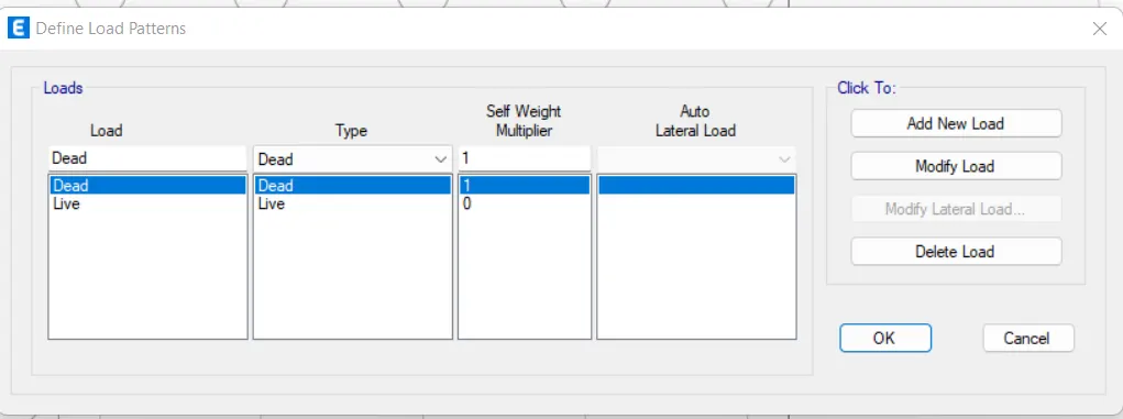
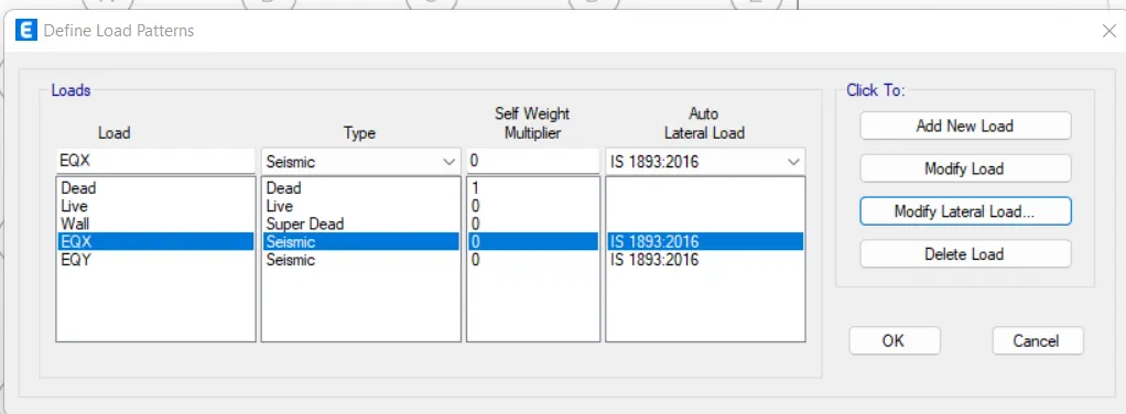
- Go to the define and select the load patterns
- set or make the loads like dead, live, wall, EQX, EQY
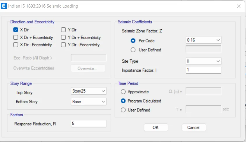
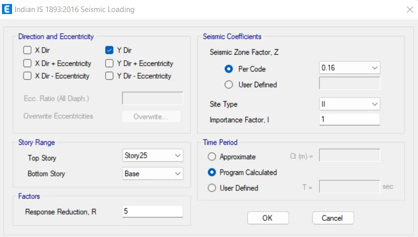
- Give the IS code value for EXQ, EXY. Taken the both load and set the (DIRECTION AND ECCENTRICITY)
- EXQ - only select the x-dirction, EXY - only select the y-dirction
- Set the seismic zone factor for per code as per the rule of code book (0.16) And set the site type as (II)
- This process is same for both the EQX, EQY, Here wall load is super dead load.
Step 12:
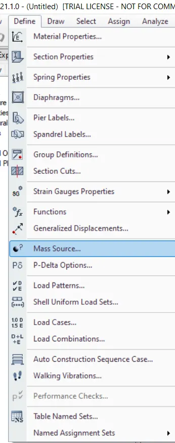
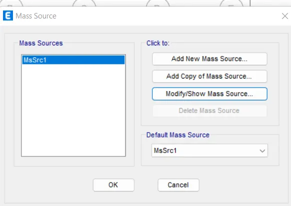
- Taken the define option and select the mass source, After opening the mass source dialouge box. Select modify option to modify it
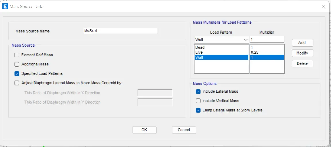
- Just select only the specify load pattern and other then unselect it And give the load patterns as dead load, live load, wall load.Give the value of the dead load and wall load as (1)
- give the value of live load as (0.25), Then click ok
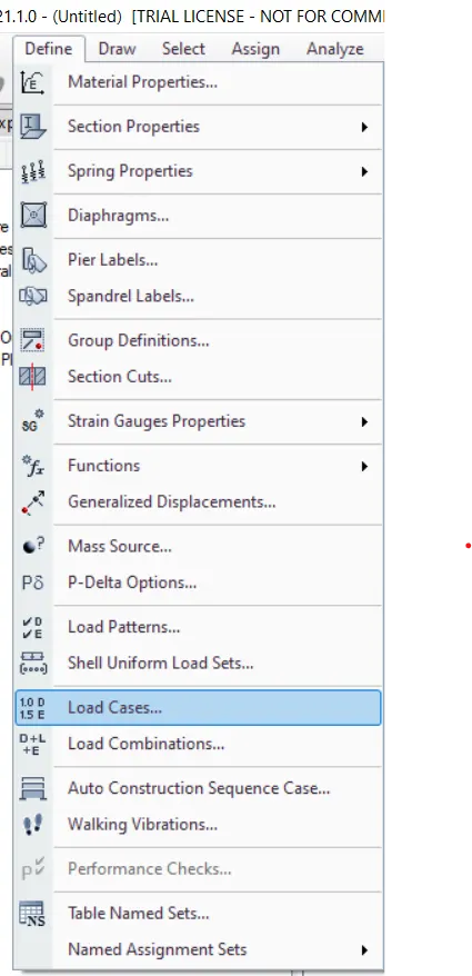
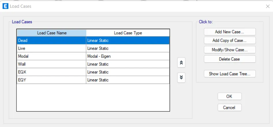
- Select the define option And select the load cases
- After opening the load cases dialouge box check once And then click ok
Step 13:
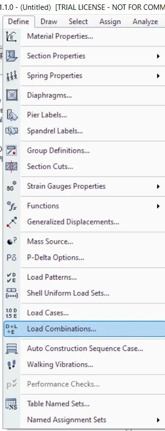
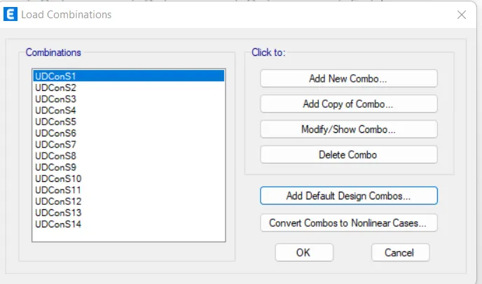
- Select the define option and select the load combination, After opening the load combination dialouge box
- Just select the concrete frame design And select "converet to user combination" option
- Then click ok
- It is seen that combination of load are automatically placed with help of code designs
- We can arrage the materials and loads on the design, go to the quick draw column option in the left to corner
- After clicking the box will appear in left bottom corner, there set the properties as we already made column
- Go the plan view and and placed the coloumn on the grid . Is shown in the below image
- Just use the replicate option to make the multiple or copy paste the column to all the grid
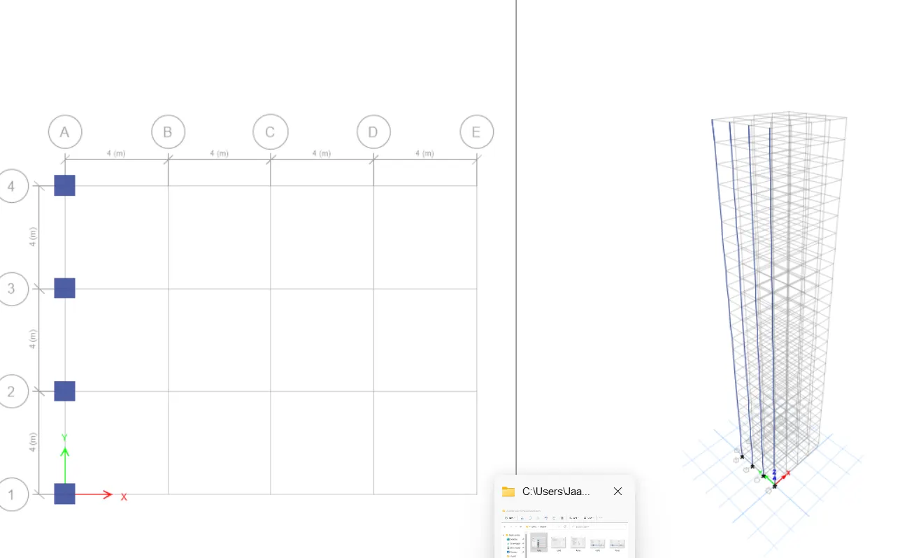
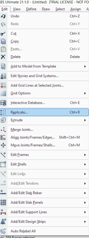
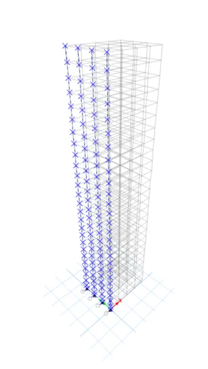
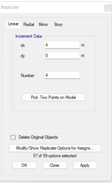
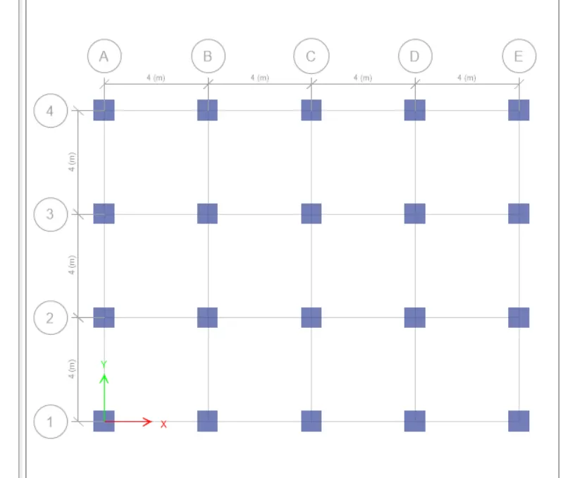
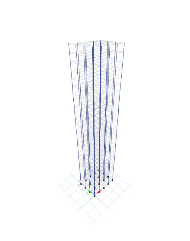
Step 14:
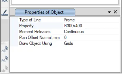
- Use the quick draw beam option in the left corner
- After clicking the box will appear in left bottom corner, here we have to set the properties as we already made beam (B300 x 400)And go to the plan view and place the column on the grid . Is shown in the below image
- Just use the replicate option to make the multiple or copy paste the beam to all the grid
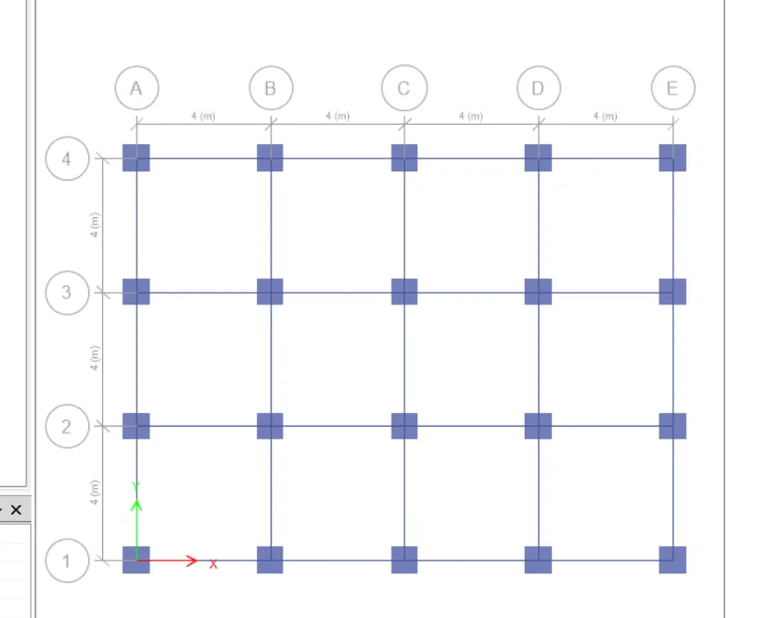
- Select the quick draw floor option to draw the slab
- select all stories and select the alredy create slab150 in the properties
- And just pick in the story ,then all slab are created as image as given below
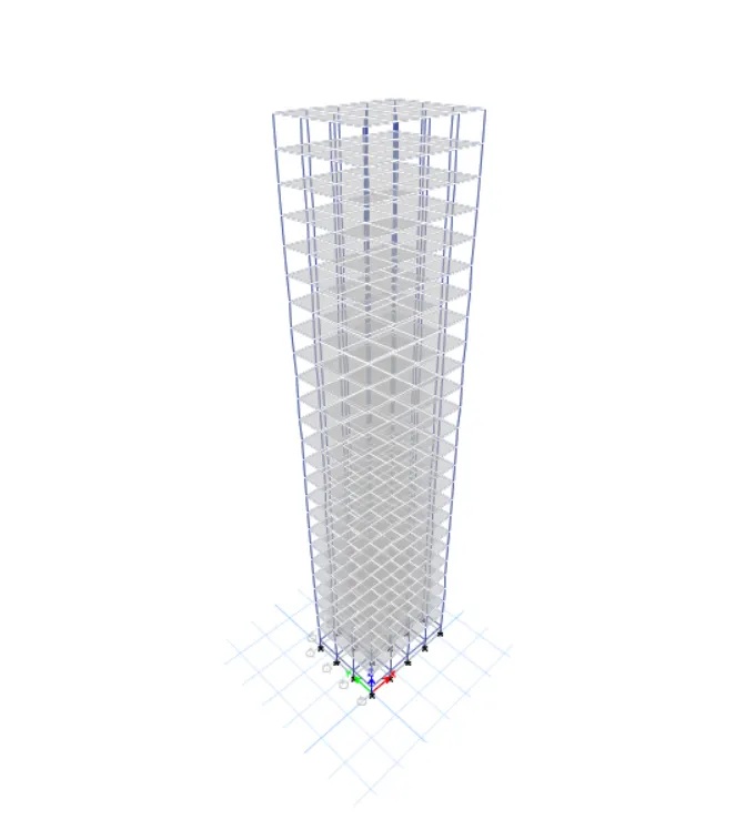
Step 15:
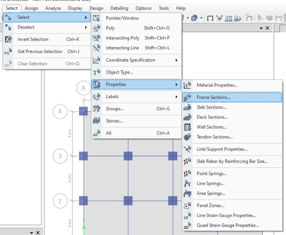
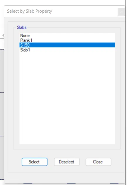
- Go to the select tab then pick the properties and select the freame sections
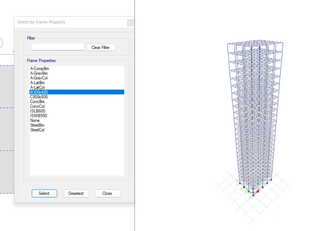
- go to the select by frame property dialouge box and Select the beams and click ok
- Then selected beams are shown in below image
Step 16 :
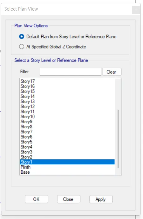
- open the selected plan views , select the story 1 option
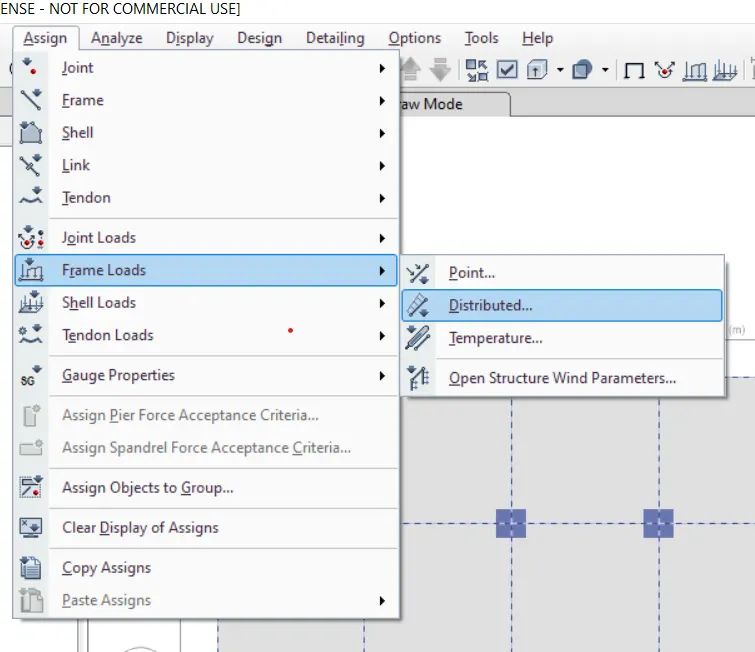
- Then select the similar story option, Go to the assign tab select the frame load And assign the distributed load.
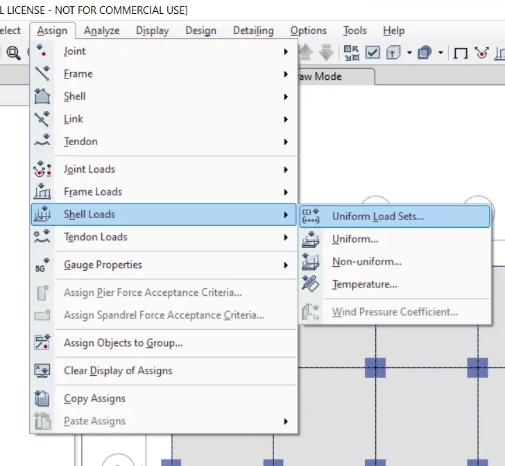
Step 17:
- Go to the assign tab and select the shell load And select the uniform
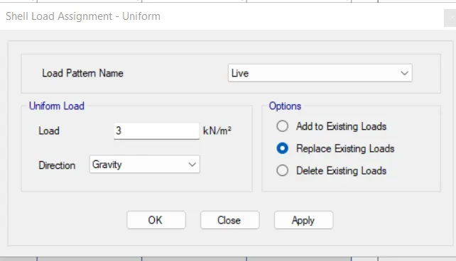
- Then there will open the (shell load assignment) dialouge box, give the load pattern name as (live load)
- Give the load value as 3 kn/m2, Finally then click ok
- The load as been assigned in the shell as been shown in below image
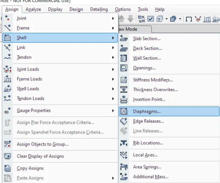
- Go to the assign tab Then select the shell and pick the diaphragms
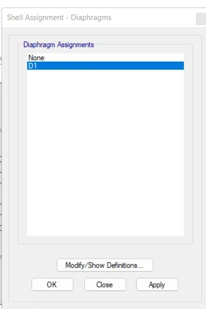
- Here open the shell assignment dialouge box
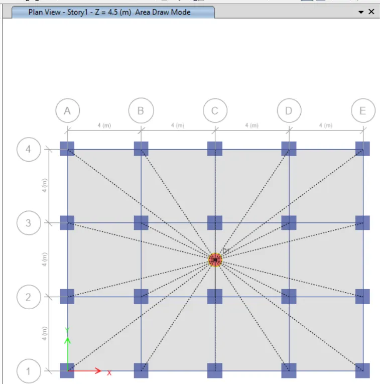
- In the dialog box select the (d1) option, the diaphragms as placed at the center of the building
- After finishing the all loads assignment
- just go to the run analysis option
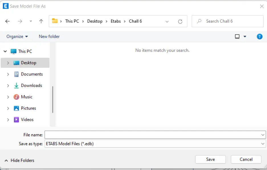
- Then in run analysis option select a save file option
- just save the file and run the analysis
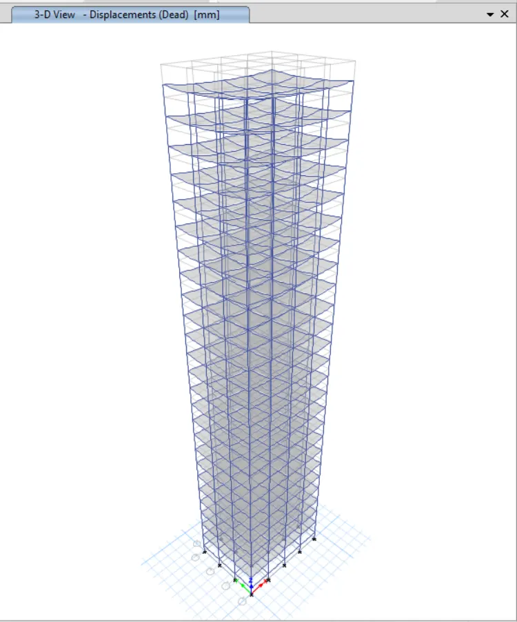
- After finishing the analysis
- the deformation of building as been shown in the screen and its shown in below the image
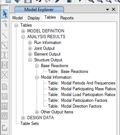
- Go to the model exploser tab ,pick the table option
- Pick the analysis results , click the structural outputs and then click the model information
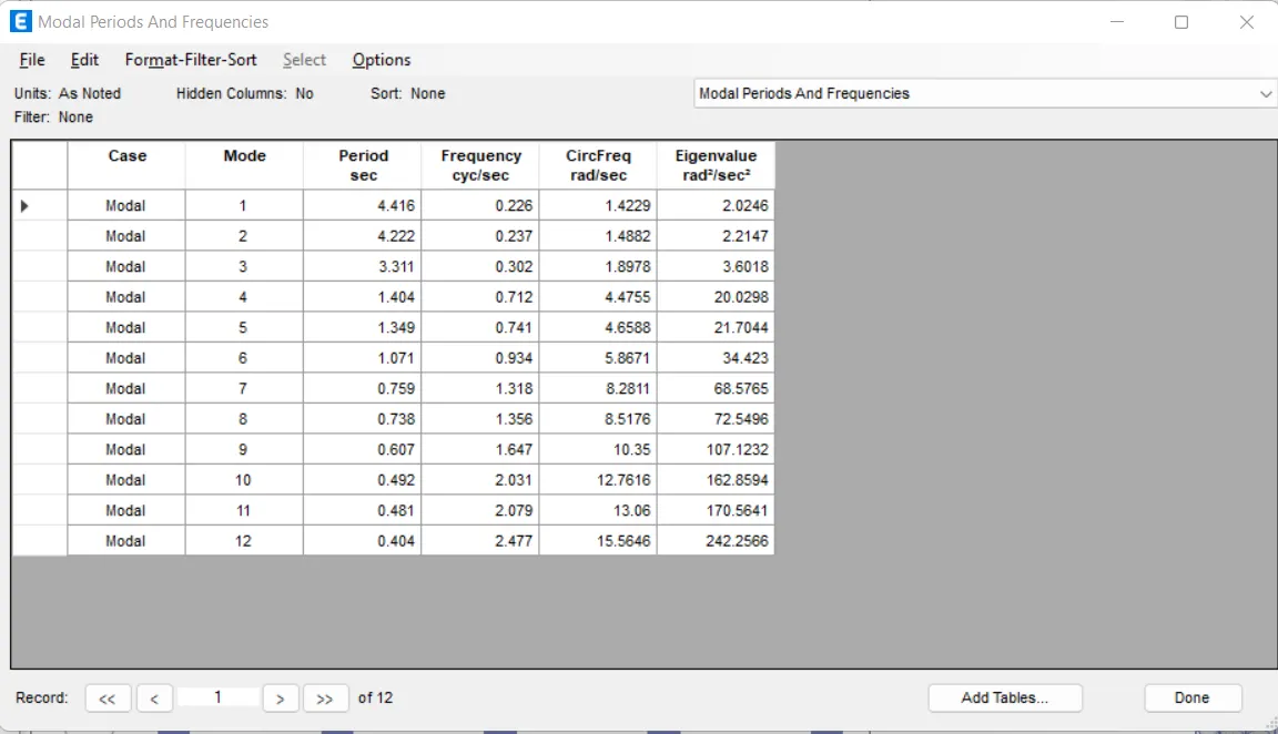
- finally check the tables from the model information, pick the tables.
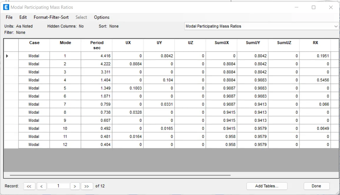
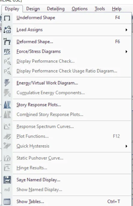
- go to the display tab, then select the story response plots
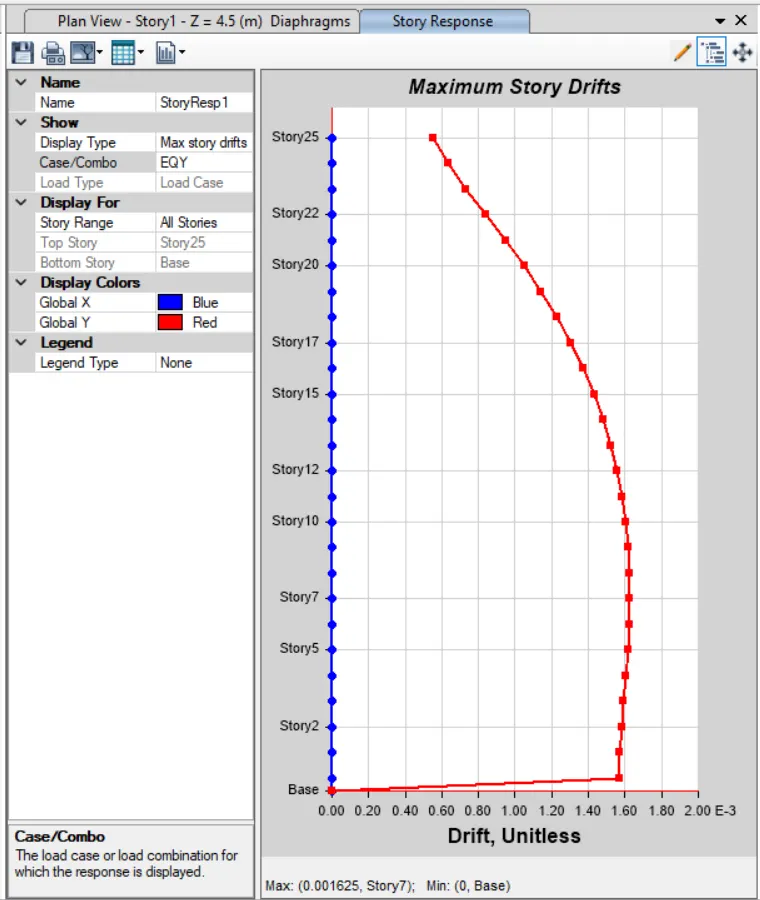
- after selection of story response plots, open the (drift for diaphragms D1) dialog box
- set the drift option and EQX,EQY . it will show the frequence diagram on the screen with values. then the image as been given below
Result :
- The modelling is completed and analysed in ETabs. The results are within given range below.
| Criteria | Desirable solution | Exercise result | |
| Fundamental Translational natural period |
X-direction Y-direction |
4.4 second 4.2 second |
4.41 4.22 |
| Torsional irregularity | IS 1893-2016(Part-1)Table-5 | Torsional mode Time period should be lesser than X and Y direction time periods | Yes |
| Vertical irregularity | IS 1893-2016(Part-1) Table-6 Clause-7 | First three modes together should contribute at least 65% in mass participation factor in each principal direction | Yes |
| Fundamental lateral natural periods in two principal plane directions are away from each other by at least 10% | No | ||
| Inter-storey Drift | IS 1893-2016(Part-1) Clause- 7.11.1.1 |
Storey drift shall not exceed 0.004 times the storey height for base shear with no load factors (4 x 10⁻³) |
Yes |
******************