Modelling of 25 storey building with the specified properties using ETABS
Modelling of 25 storey building with the specified properties using ETABS
Aim: Modelling a 25 story building on ETABS 2018 with structural properties including Ground floor or plinth floor level at a height of 1.5 meters from the base and a story height of 3 meters.
Structural Element Sizes
- Beams : 300 × 400 mm
- Columns : 800 × 800 mm
- Slab : 150 mm thick
Material Properties
- Grade of Concrete : M30
- Grade of Steel Reinforcement Bars : Fe 415
Loading
- Dead Load on beams from infill wall : 10 kN/m(Let us assume the same for roof floor in view of parapet)
- Live load on floor : 3 kN/m2 (Let us assume the same for roof floor)
a) Buildings are assumed to be pinned at the base
b) All columns in all storey are of the same size
c) All beams in all storeys are of the same size
d) Building is located on Soil type-II and in Zone-III. Assume other factors if required.
Procedure:
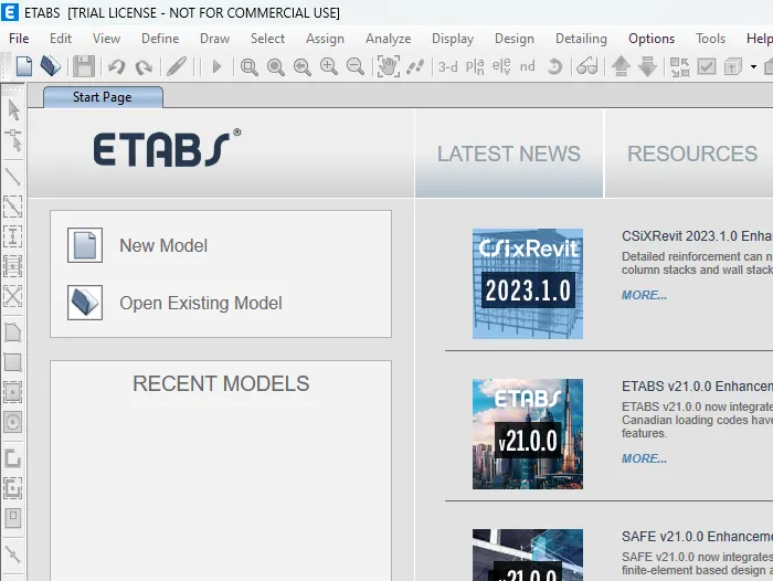
Step 1: Opening New File
- Open ETABS 21 application
- Click the File menu and choose to Create a New Model option from there.
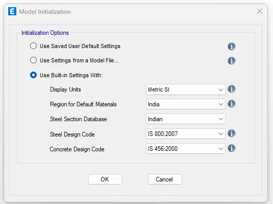
- After choosing a New model a dialogue box will appear which is known as Model Initialization.
- Choose the Built-in settings option and select the display units and codes.
Step 2: Customizing Grid and Story
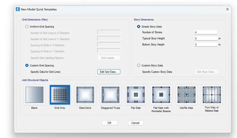
- After the model initialization needs to select Grid and Story inputs from the New model quick templates dialogue box.
- In the dialogue box choose custom grid spacing and custom story data which is used to provide the inputs as per requirnment.
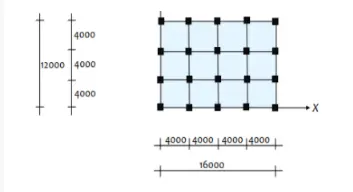
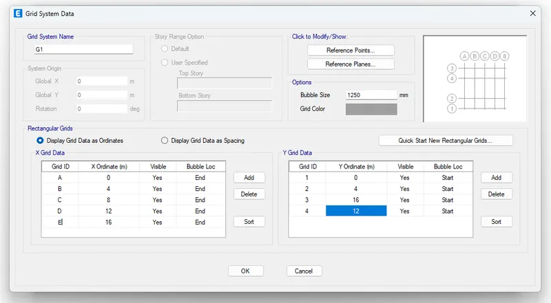
- In the Grid system data dialogue box, set x grid data as 5 numbers at a distance of 4m and also set Y grid data as 4 numbers at a distance of 4m. as shown below :
Step 3: STORY DATA
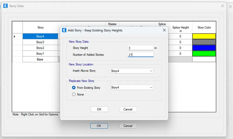
- In a story data dialogue box, need to input all the relevant details about the story .
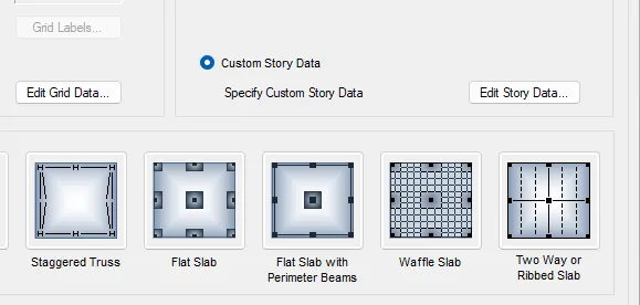
- Click on CUSTOM STORY DATA and add a story as per requirenment, here we need Plinth and 25 story
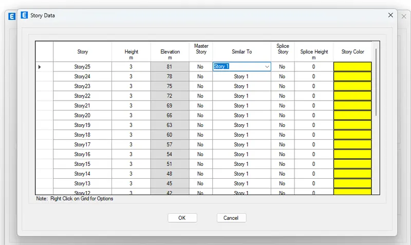
- Put 3m height for all the story except plinth
- Make 1st story as Master story
- Choose all other stories as similar to 1st story.
Step 4: 3D and PLAN VIEW IN SPLIT SCREEN
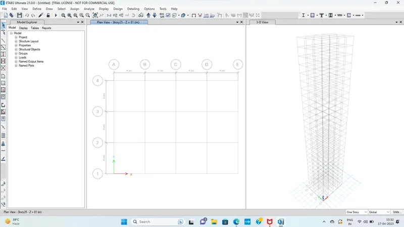
- On the top right corner click the drop-down arrow
- Choose New window option
- Now the screen splits into two.
- Here, we can see the plan and elevation of each story simultaneously
Step 5:APPLYING PROPERTIY TO MATERIAL
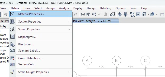
- Click Define tab
- Choose Material properties
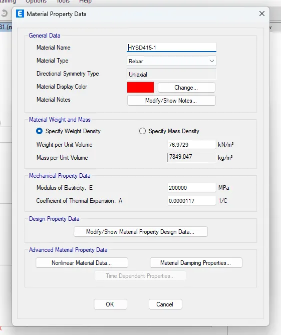
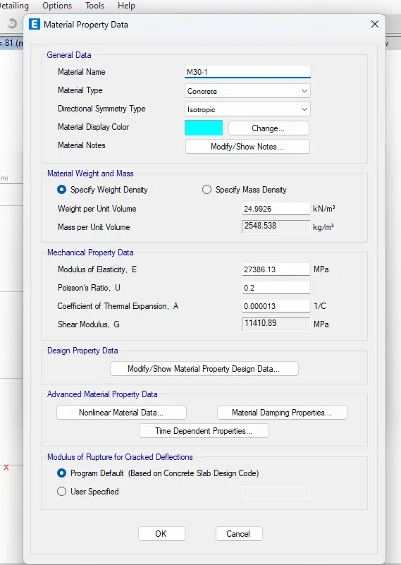
- After clicking ok for Add New Material Property dialogue box it redirects into another dialogue box called Material property data.
- In this data all the relevant data values are assigned default as per IS code which we set previously. here M30 grade of concrete is added and for steel/rebar hysd 415 is added as shown below
- Rename the Property name
- Select the material as M30
- Choose modeling type as Membrane from the drop-down list
- Now add section Properties , add Beam and Column
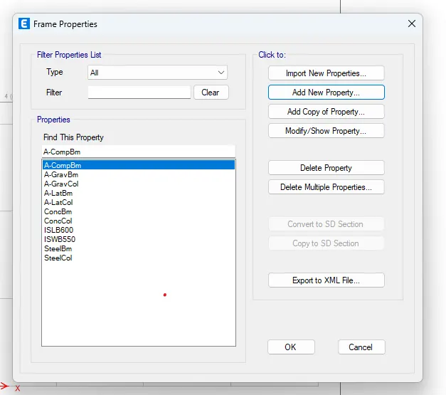
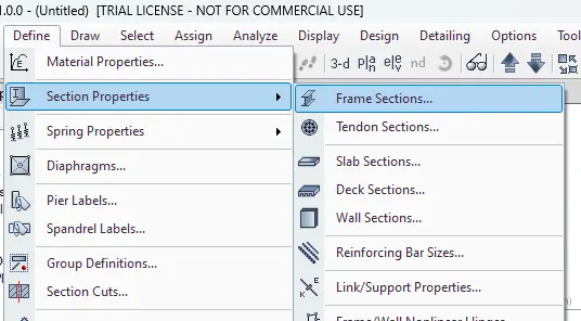
- Go to section properties then go to Frames section , Add new property. Now select the square/rectangle shape for Beam and Column as shown below
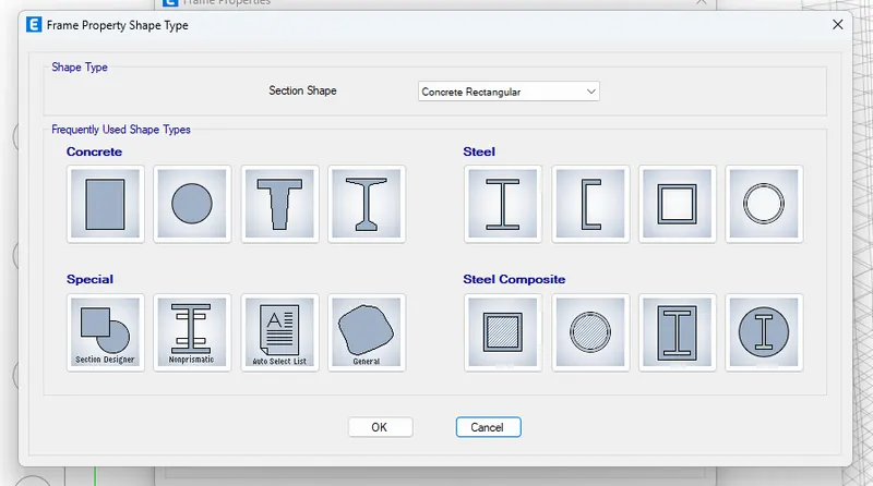
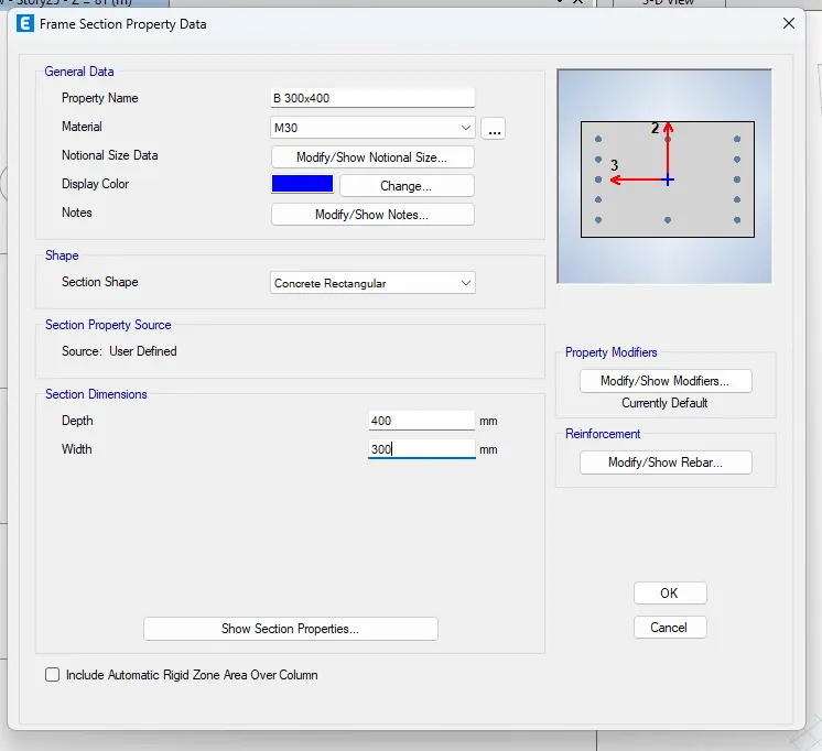
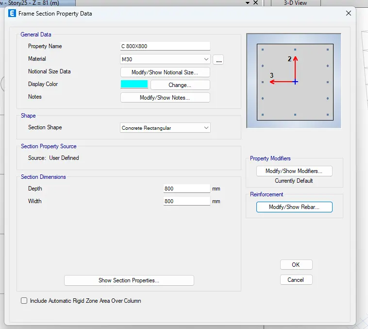
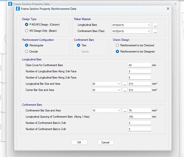
Step 6: SLAB PROPERTY
- After applying the properties of Beams and columns we need to apply the property of Slab
- Click Define menu and choose Section properties
- Select Slab Sections
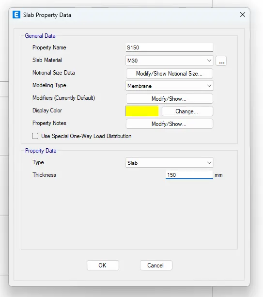
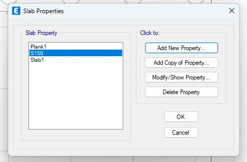
Step 7: LOAD PATTERNS
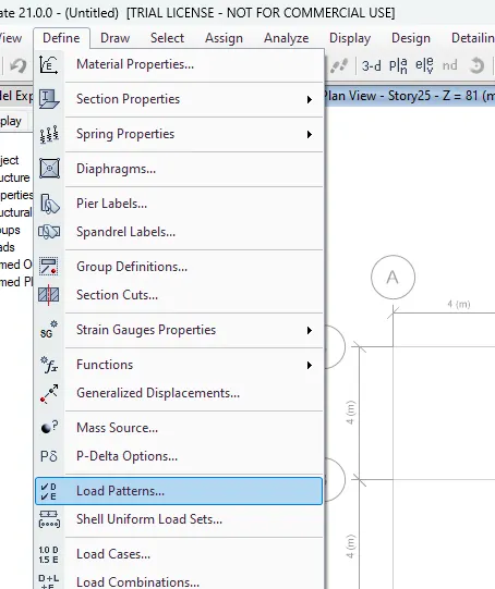
- Click Define , then go to Load Pattern
- Add new load as Brickwall, EQX with both positive and negative eccentricity as per IS 1893:2016
- Similarly add EQY with positive and negative eccentricity
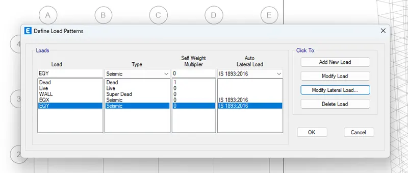
- Change the properties of EQX and EQY as shown below
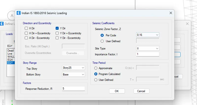
- Now check the Mass Source Datat , if the introduced Loads are visible/added to the model and also check the Load cases , as shown below
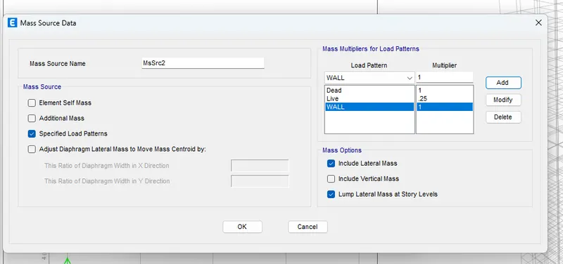
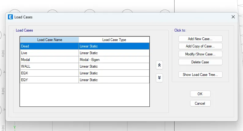
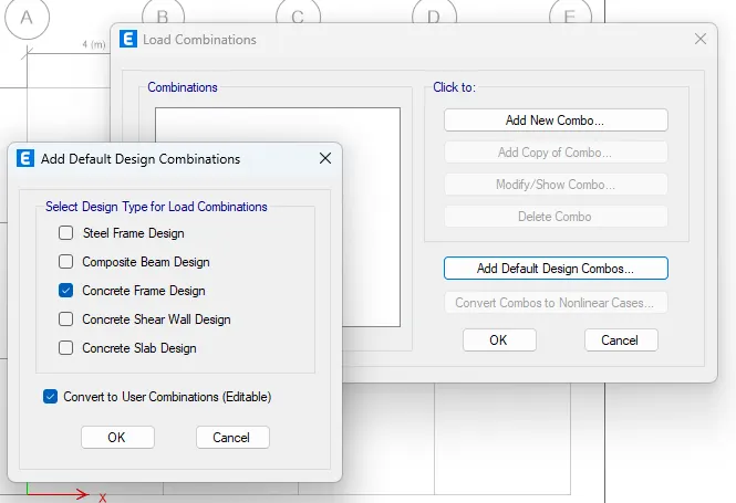
Step 8: LOAD COMBINATION
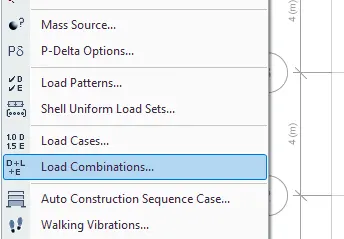
- one of the important steps for modeling is to set load combination
- Click the Define tab
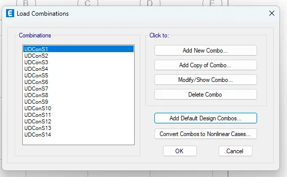
- Immediately ETABS will give you various load combinations as per the code which we are set previously
- Select Load Combinations
- Select Concrete frame design
Step 9: INSERTING Columns , Beams and Slab :
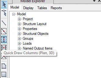
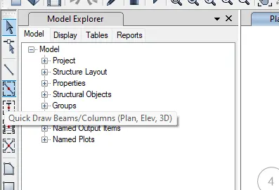
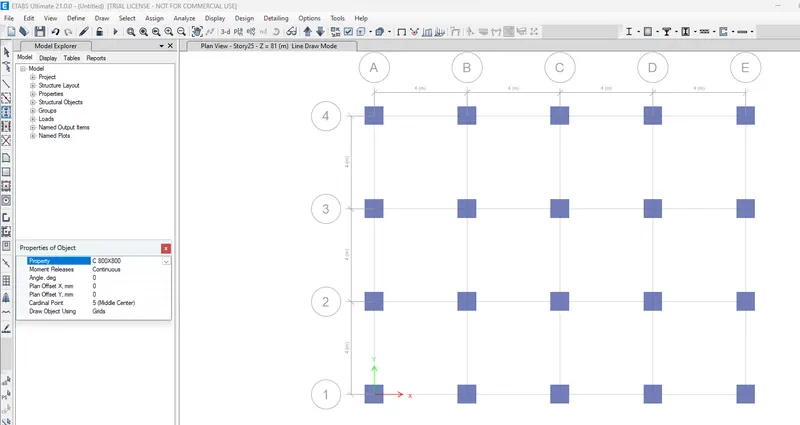
- To drawing the columns and beams in Etabs just click the Quickdraw columns tool in the model tree
- After clicking the tool, the property tab will appear on that tab all the relevant detail about the particular objects will show.
- Draw the Columns in accordance with the grids
- Click the Select object tool to discard the drawing
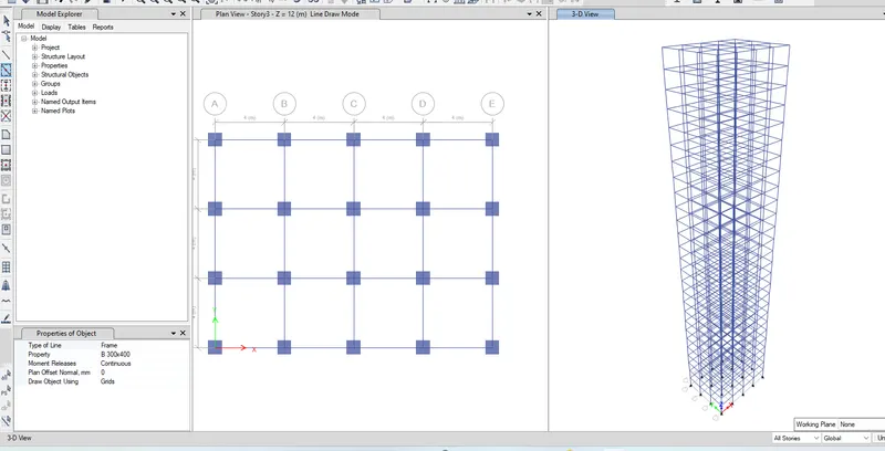
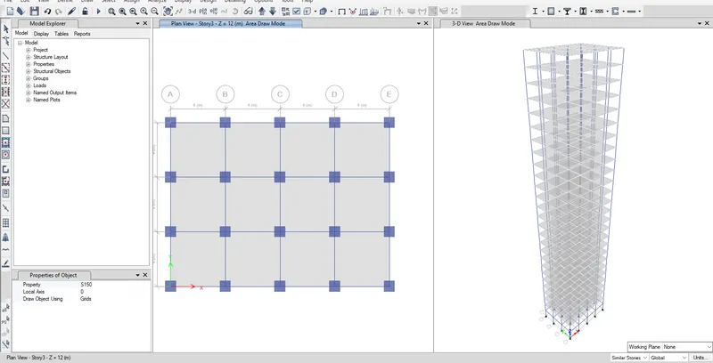
- To drawing the Slab in Etabs just click the Quickdraw Floor/Slab tool in the model tree
- Draw the slab by clicking the middle portion og the squre grid, and keep checking the bottom lines where all story /similar story should be selected
Step 10: ASSIGNING LOADS TO THE MODEL
- click the Select tab
- choose Porperty type , then select the Distributed for beam load
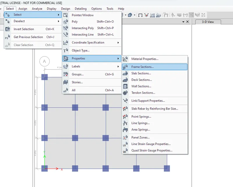
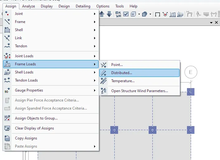
- Assign the live loads for all the beams
- click the Select tab
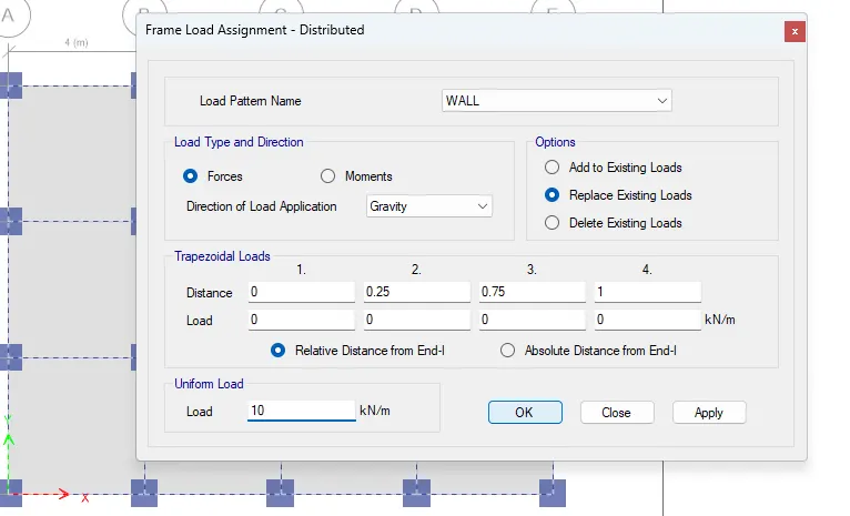
- choose Porperty type , then select the Distributed for beam load
- Choose the load pattern name from the drop-down list
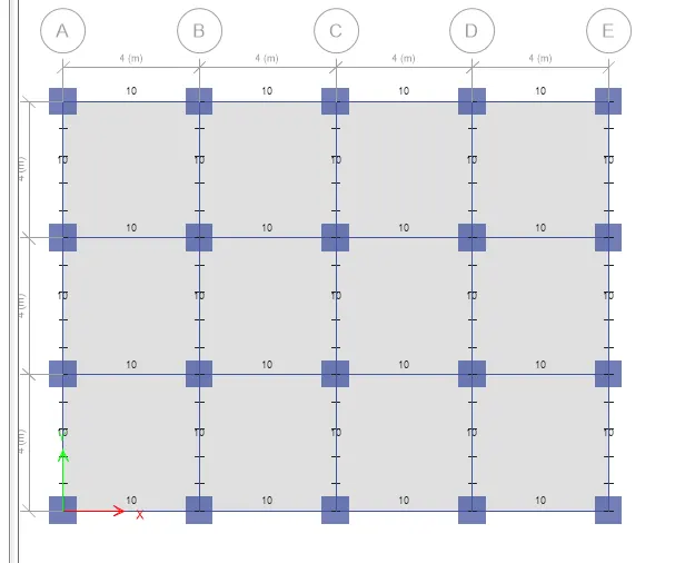
- Set Frame/wall load as 10Kn/sq.m
Step 11: LOAD APPLICATION ON SLAB
- Click Define tab
- Choose Load Patterns
- After providing the load inputs need to assign the shell loads of each story
- Change tab as Similar story
- Select the entire grids
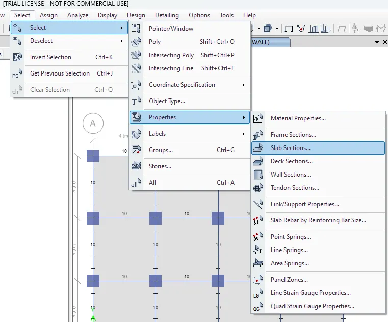
- Click the Assign tab and choose Shell loads
- Select Uniform
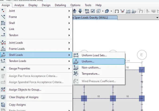
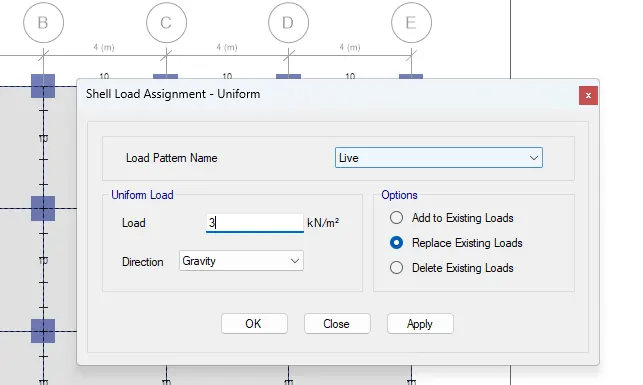
- For Live load distribution follow the
- Choose the load pattern name from the drop-down list
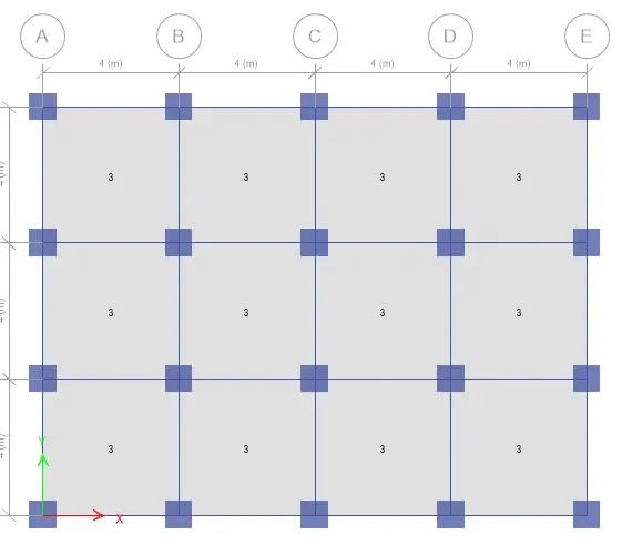
- Set Live load as 3 Kn/sq.m
- To view the loads click the toggle option on top of the screen
- And rotate the view where we can see the loads applied.
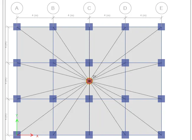
Step 12: ASSIGNING DIAPHRAGM
- Final step of analysis is to set Diaphragm
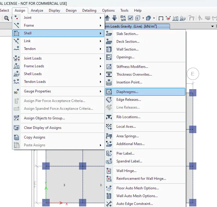
- Click the Assign tab
- Choose shell and select Diaphragm.
- Choose an all story option from the bottom of the screen
- Click the check tab
- And check the model is there any mistakes. if not go ahead the analysis.
Step 13 : LOCK THE MODEL AND RUN ANALYSIS
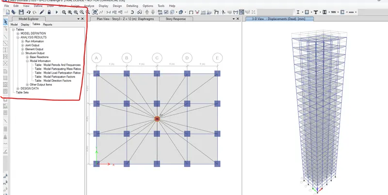
- Lock the model and run the analysis and the screen will show all the details on the left side of screen
Result:
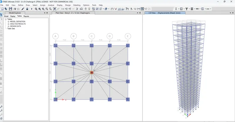
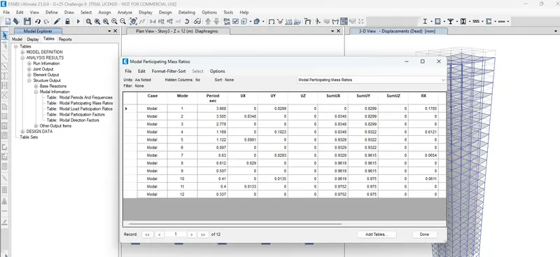
- After the analysis option-click result tab
- we can see the result by selecting loads separately.
- Check if the translational fundamental natural period of vibration in both the x and y direction is approximately: Tx1">Tx1= 4.4 second Ty1">Ty= 4.2 second.
- Here in the result it comes 3.68 at point 1 and 3.05 at point 2 , so it is satisfactory
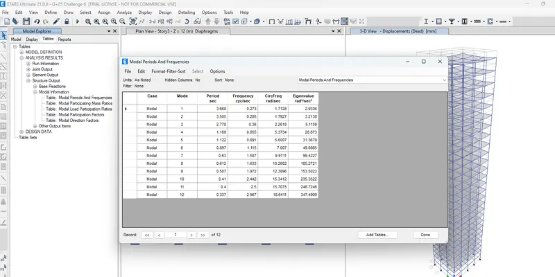
- Check if the following provision in Table 5 of IS 1893 (part 1) – 2016, on torsional irregularity satisfied: The natural period corresponding to the torsional mode of oscillation must be less than the two fundamental translational modes of oscillation along each principal plan directions.
- Here the mode 1 is 82 % and mode 2 is .1023 so it is above 90% , hence satisfactory
- Check if the two provisions of clause 7 in Table 6 (shown below) of IS 1893 (part 1) – 2016, regarding vertical irregularity is satisfied
- Yes
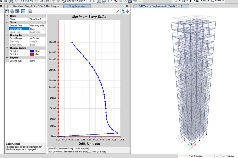
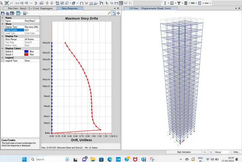
- Check if provision on inter-storey drift limitations in clause 7.11.1.1 satisfied. Please note that this check is for Serviceability Limit State and hence is for situation when stucture is subjected to unfactored seismic base shear
- yes it is 1.20 in EQX and EQY