Modelling of 25 storey building with the specified properties using ETABS
Aim-To model a 25 storey building on ETABS with structural properties as specified.
Introduction- Ground floor or plinth floor level can be taken at a height of 1.5 metres from the base. Each of the successive 25 storeys has a storey height of 3 metres.
Structural Element Sizes
- Beams : 300 × 400 mm
- Columns : 800 × 800 mm
- Slab : 150 mm thick
Material Properties
- Grade of Concrete : M30
- Grade of Steel Reinforcement Bars : Fe 415
Loading
- Dead Load on beams from infill wall : 10 kN/m (Let us assume the same for roof floor in view of parapet)
- Live load on floor : 3 kN/m2 (Let us assume the same for roof floor)
a) Buildings are assumed to be pinned at the base
b) All columns in all storey are of the same size
c) All beams in all storeys are of the same size
d) Building is located on Soil type-II and in Zone-III. Assume other factors if required.
Procedure-
-Open ETABS
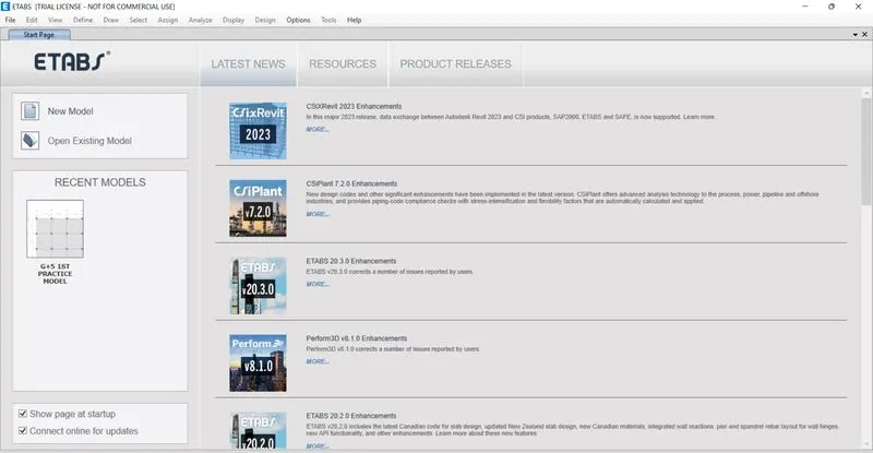
-Select New model
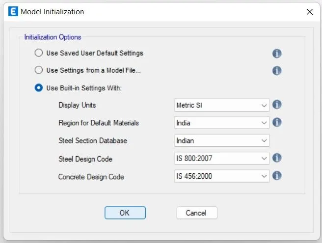
-set metric as a unit and set Is code
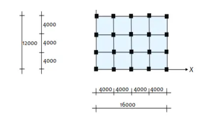
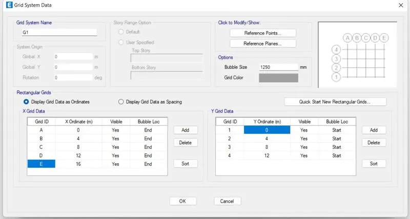
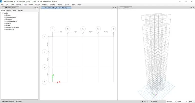
-Select customised grid option>Click on edit>following window display as per given set grids in x and y direction with respective their dimension as shon below>Ok
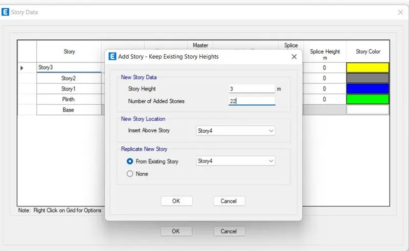
-Select customised story option>Selct edit>Rename story 1 as a Plinth and give height 1.5 and remaining story start from Story 1>To add new story right click at last story>select keep existing height>set it as given below>Ok
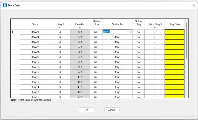
-Now set story 1 as a master story so except Plinth ans story 1 all other stories in Master story column will be No and in similar story column except plinth and Story 1 alll other stories are similar to Story 1
-Following windows appear keep 3d and plan view only
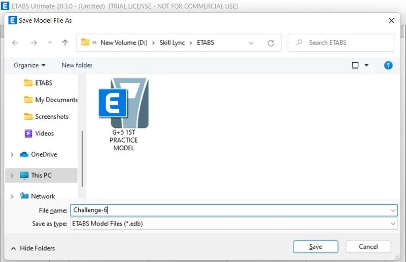
-Save file by ctrl s as a Challenge-6
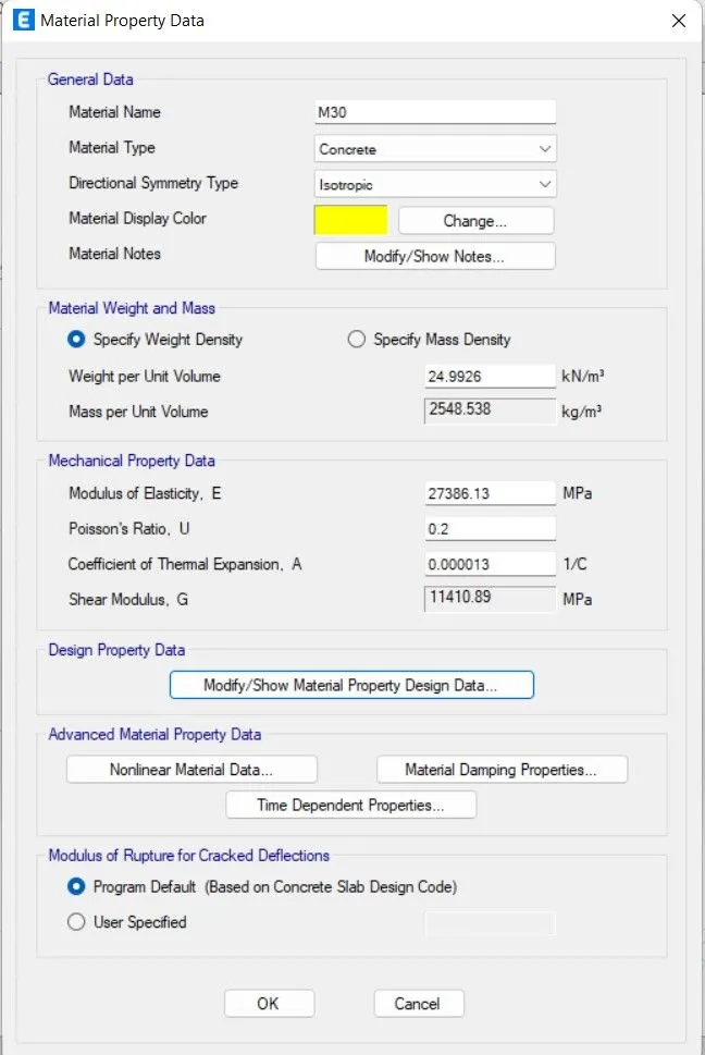
-To give material Select Define>Select material>Selet Add new material>first add Concrete M30>Ok>Property window shows set as M30>Ok
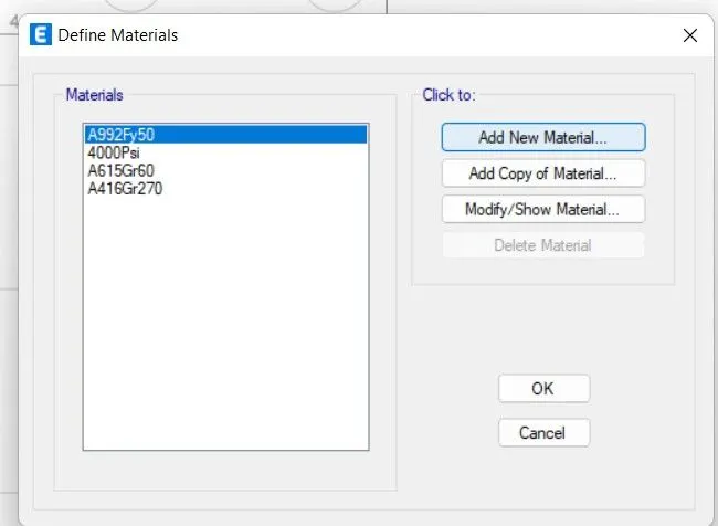
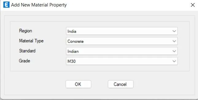
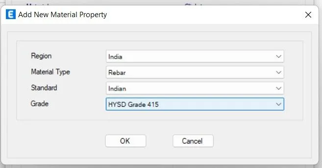
-To give material Select Define>Select material>Selet Add new material>Add rebar 415>Ok>Property window shows set as below>Ok
-Now add sections
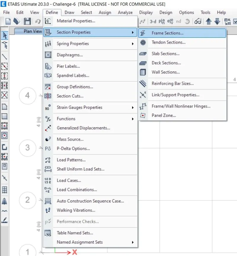
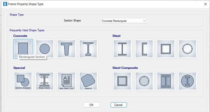
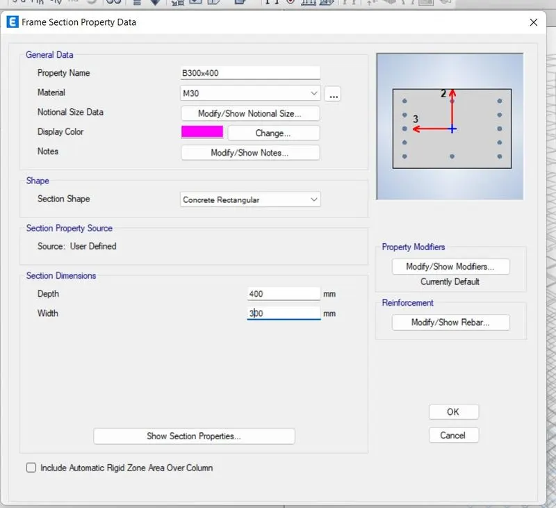
-Select Define>Select section properties>Select frame section>Select Rectangluar section>Set beam first as name B300x400>give property as shown below>Ok
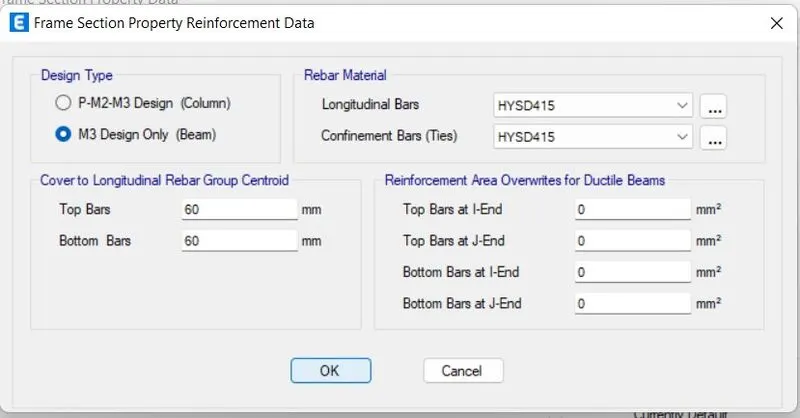
-Select Reinforcement modify option>Set as shown below
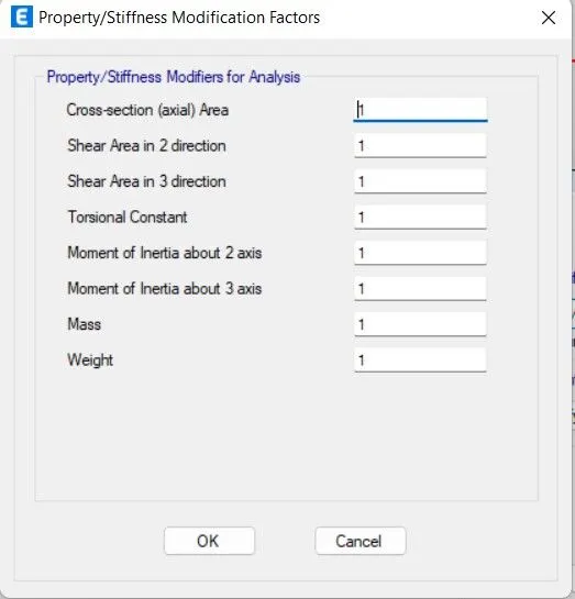
-Select property modifier modify option for now there is no changes
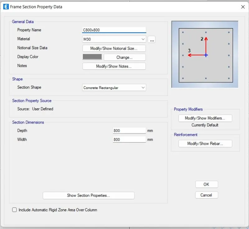
-Select Define>Select section properties>Select frame section>Select Rectangluar section>Set column name C800x800>give property as shown below>Ok
-Select Reinforcement modify option>Set as shown below
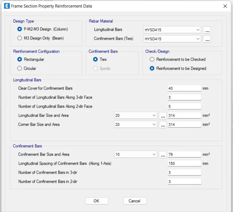
-Select property modifier modify option for now there is no changes
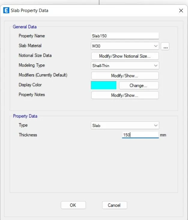
-To add slab section
-Select Define>Select slab section>Select add new slab section with name slab 150>Give thickness 150>ok
-Add Load
-Select Define>Select Load pattern>there is Dead and Live load already present add wall load and Eqx, Eqy seismic load
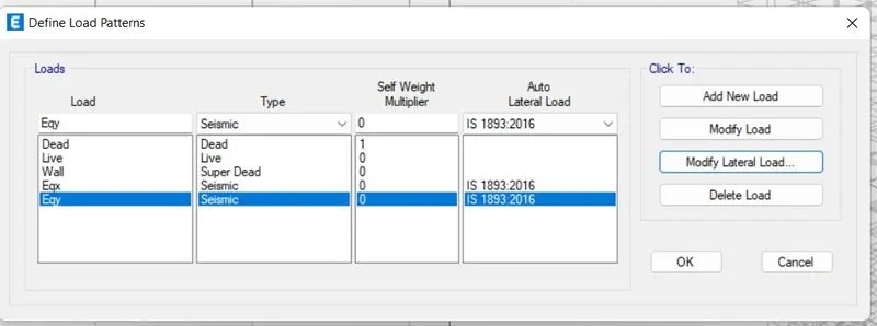
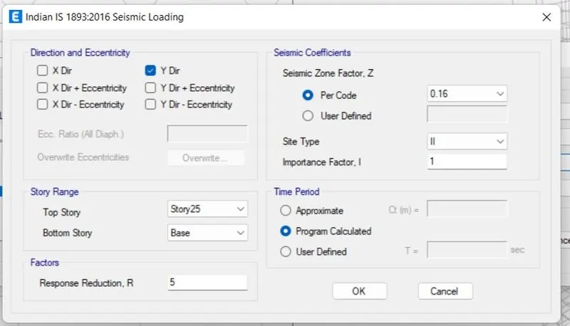
-Now select Eqx>Seelct modify lateral load>Set as given below
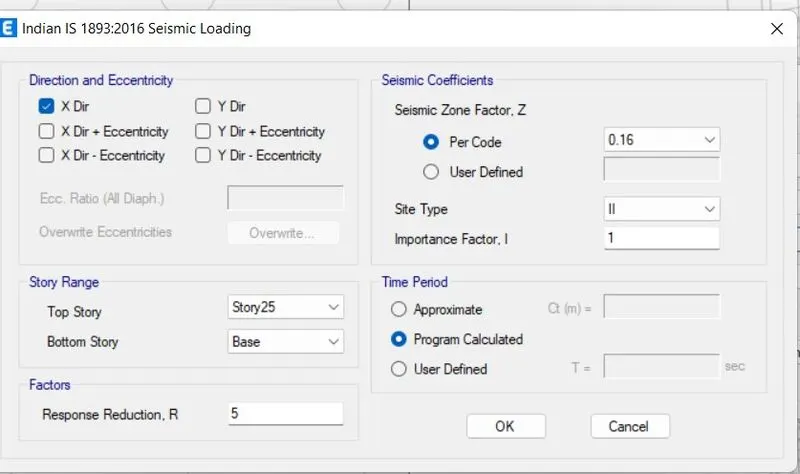
-Now select Eqy>Seelct modify lateral load>Set as given below
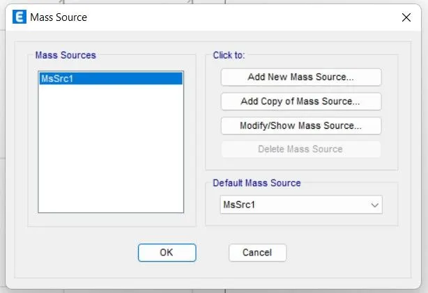
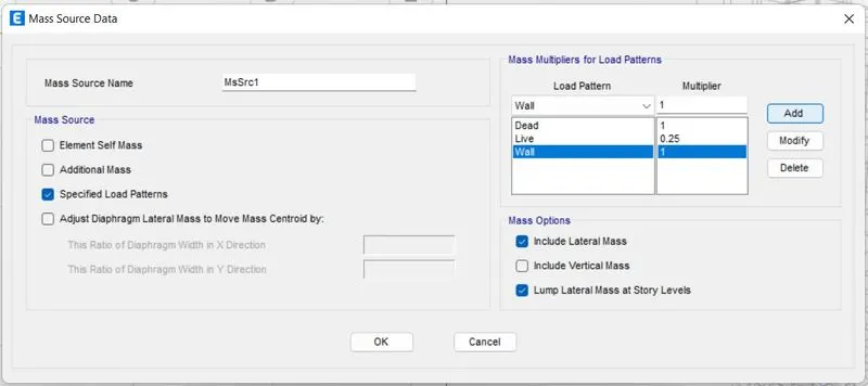
-Select Define>Select mass source>Select present source msrc1>Select modify option>Selection option select and add load with factors respectively>ok
-Now draw column, beams, and slab
-On left hand side select Quick draw column option and select size that we created earlier
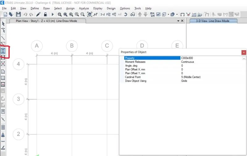
-Select intersection of grids and draw columns
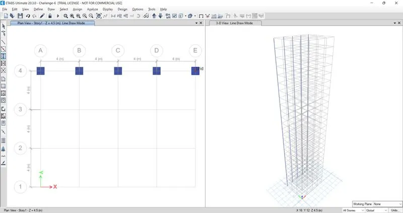
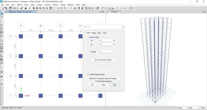
-Select all columns and Select edit option>Select Replicate option>Set dx and dy value
-On left hand side select Quick draw beam option and select size that we created earlier
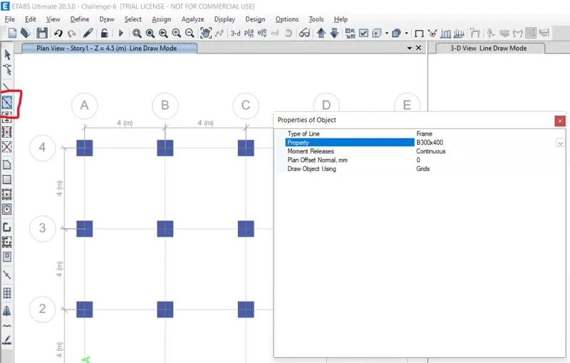
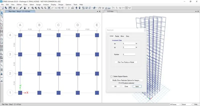
-Select grid nd draw beam, now select beam choose replicate option from edit
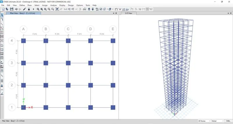
-On left hand side select Quick draw floor option and select size that we created earlier
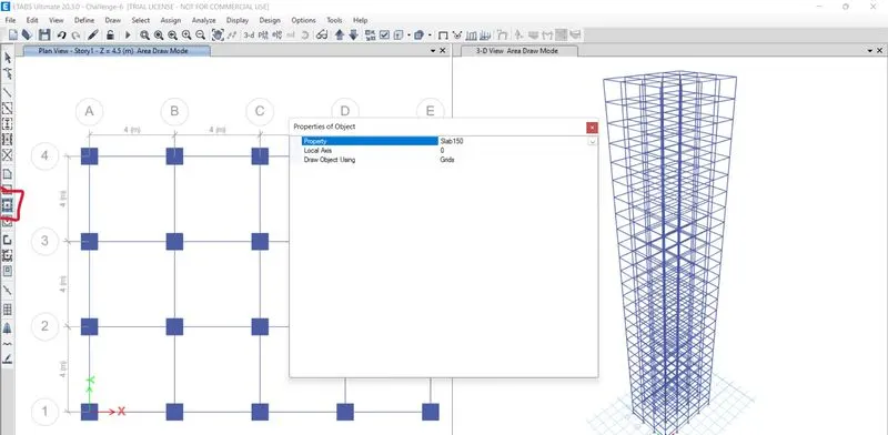
-Click anywhere between particlualr grids and draw slab
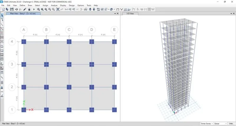
-Now apply load on it
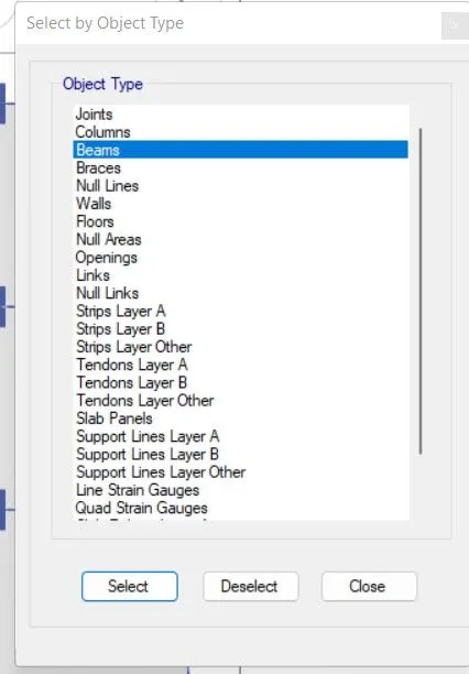
-Click on select option>Select objecttype>Select floor
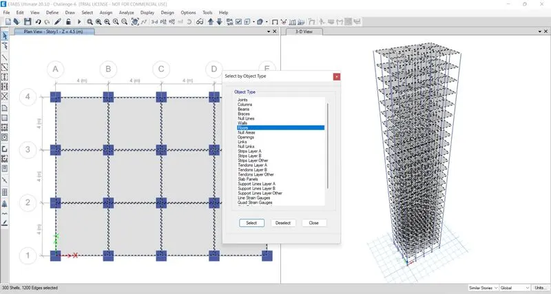
-Select Assign>Select shell load>Select live load as 3kn/m
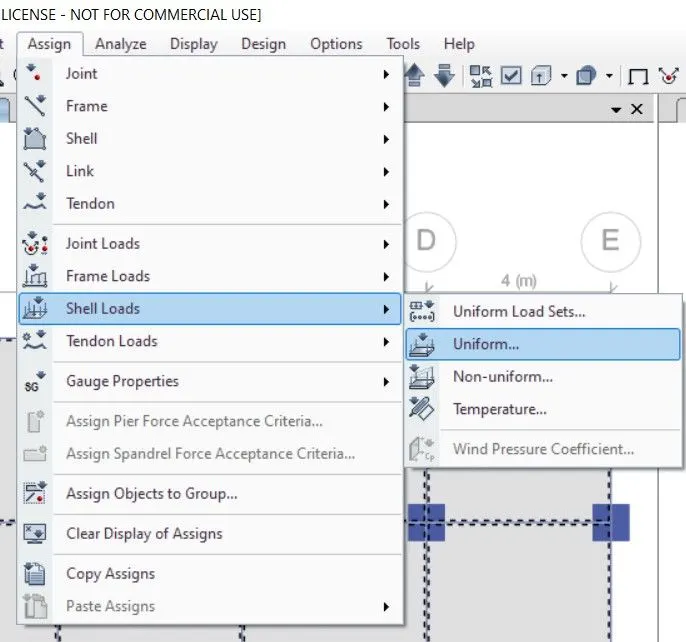
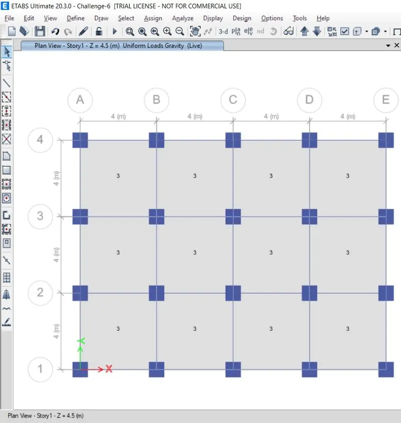
-Similarly seelct beams
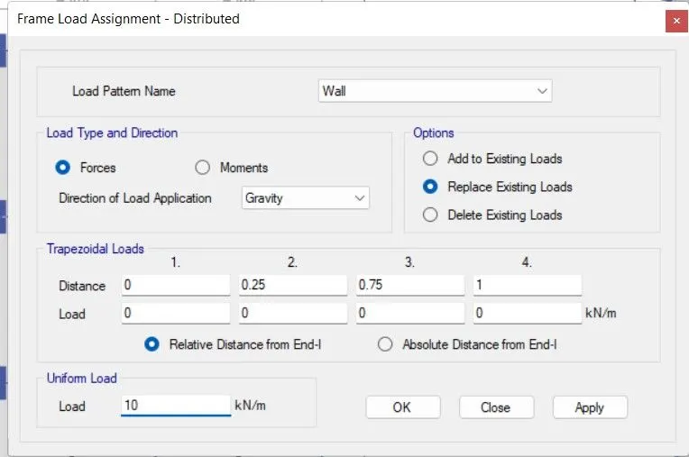
-Assign>Select frame load>select wall load 10
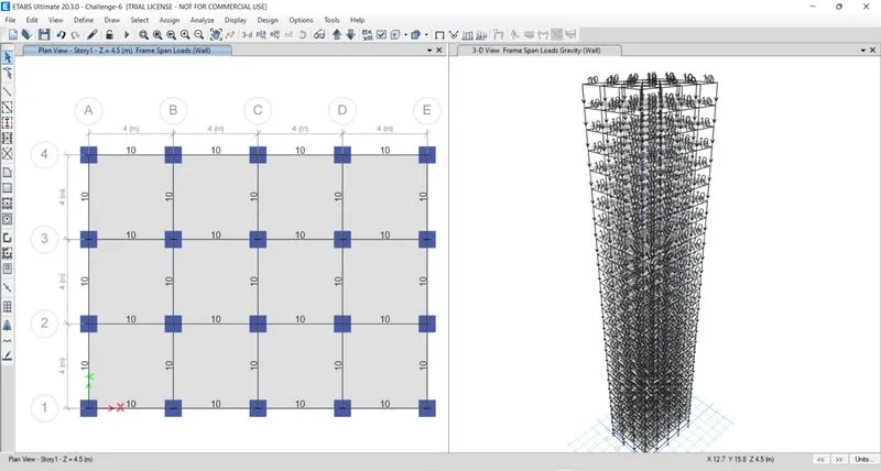
-Click on select option>Select objecttype>Select floor
-Seelct Assign>Select Shell>Seelct diaphgram
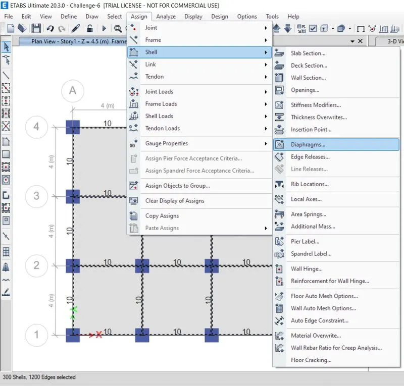
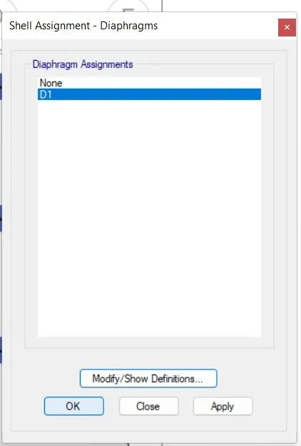
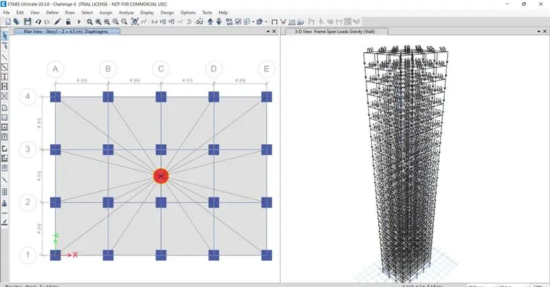
-Now run analysis
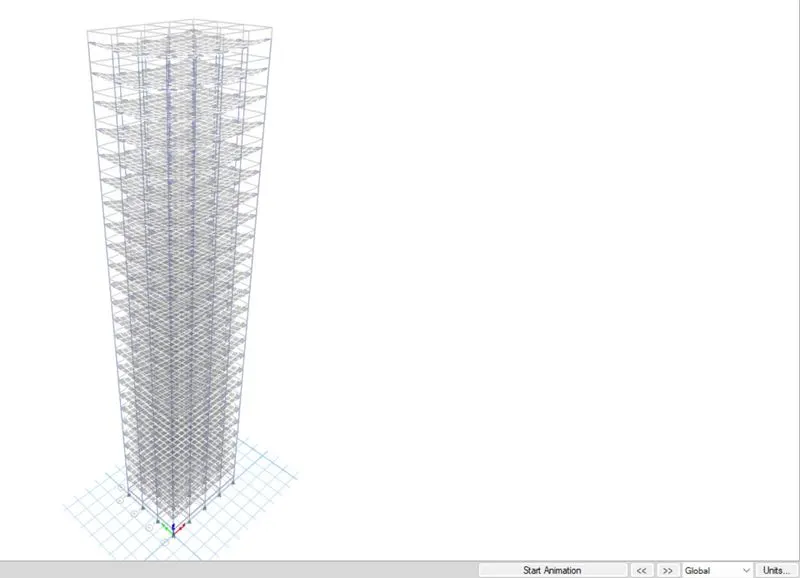
Result-
The translational fundamental natural period of vibration in both the x and y direction is approximately: Tx1Tx1= 4.4 second Ty1Ty1= 4.2 second
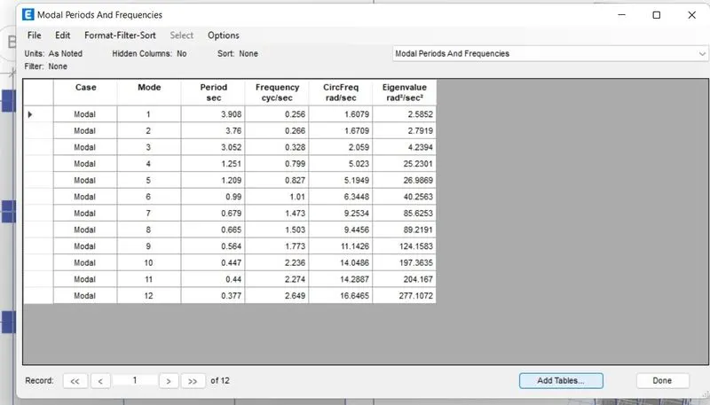
The natural period corresponding to the torsional mode of oscillation is less than the two fundamental translational modes of oscillation along each principal plan directions.
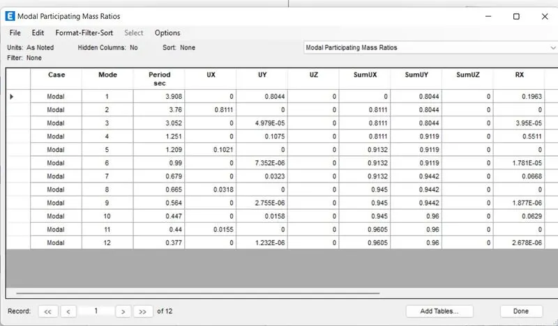
Two provisions of clause 7 in Table 6 (shown below) of IS 1893 (part 1) – 2016, regarding vertical irregularity is satisfied.
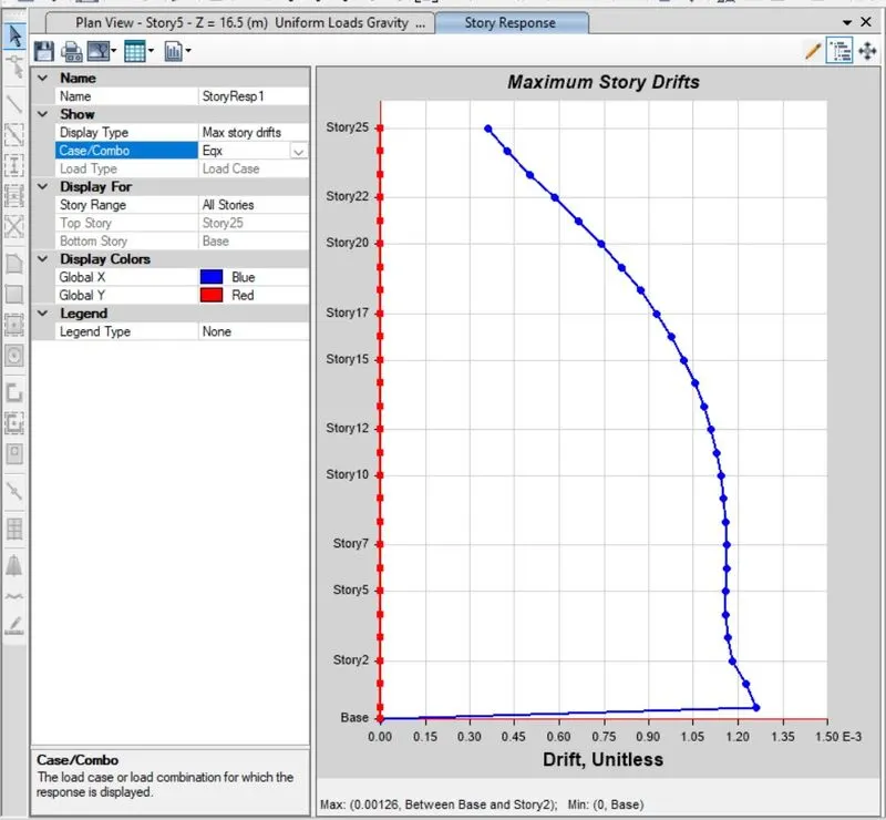
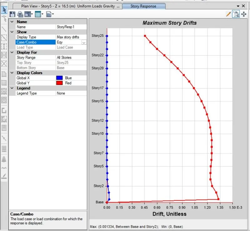
Provision on inter-storey drift limitations in clause 7.11.1.1 satisfied.