Modelling of 25 storey building with the specified properties using ETABS
1) Aim & Introduction : Model a 25 storey building on ETABS with structural properties as specified below. Ground floor or plinth floor level can be taken at a height of 1.5 metres from the base. Each of the successive 25 storeys has a storey height of 3 metres.
Structural Element Sizes
- Beams : 300 × 400 mm
- Columns : 800 × 800 mm
- Slab : 150 mm thick
Material Properties
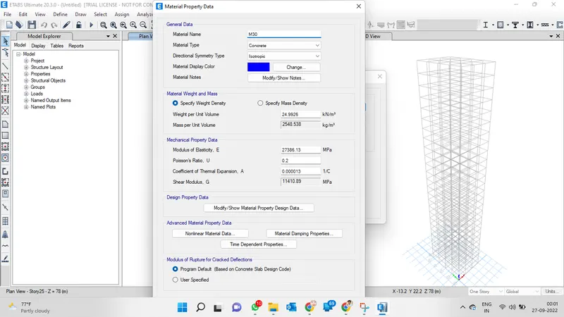
- Grade of Concrete : M30
- Grade of Steel Reinforcement Bars : Fe 415
Loading
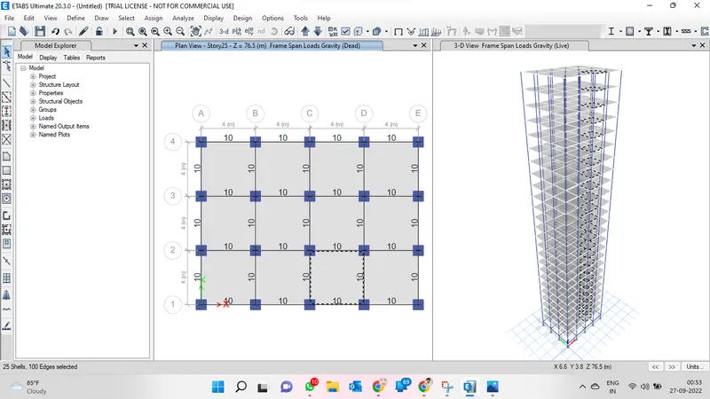
- Dead Load on beams from infill wall : 10 kN/m (Let us assume the same for roof floor in view of parapet)
- Live load on floor : 3 kN/m2 (Let us assume the same for roof floor)
a) Buildings are assumed to be pinned at the base
b) All columns in all storey are of the same size
c) All beams in all storeys are of the same size
d) Building is located on Soil type-II and in Zone-III. Assume other factors if required.
Procedure :
- Open a New Model from etabs software
- Choose the option as built in settings and change the repsective according to code book for the respective materials,this dialog box is shown below
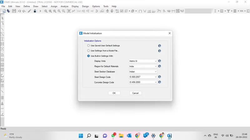
- Quick template box gets opened and by choosing the custom grid spacing option we can edit the grid data as shown below
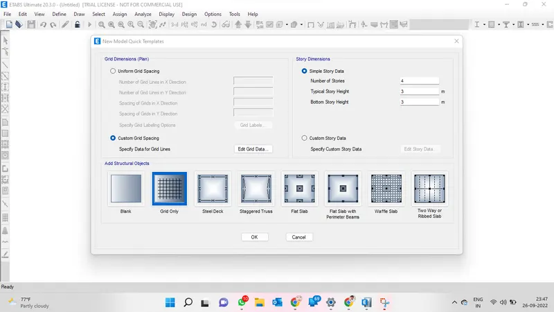
- In eidt grid data we can edit it using either from coordinates or by spacing in this we are using spacing by adding the respective datas the grid line has been formed as shown below.
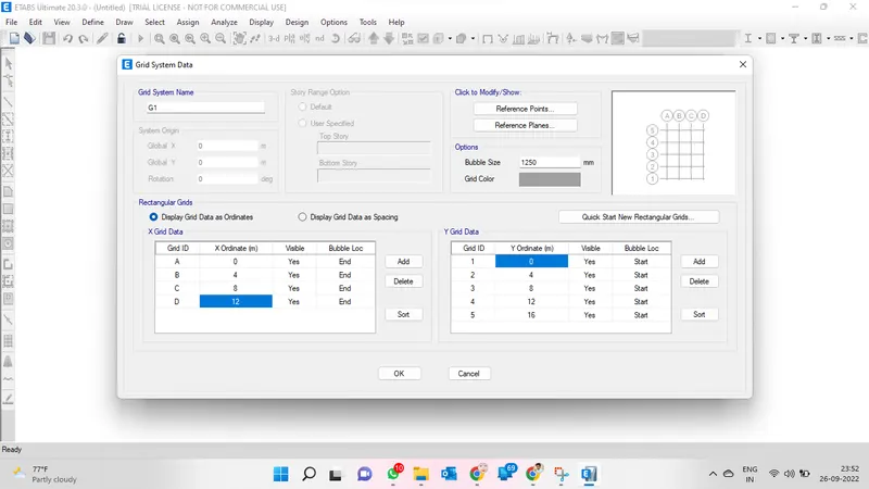
- By choosing the custom storey data we can edit the number of story in it and the height of it is calculated simulatneously as shown below
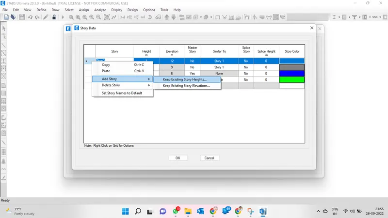
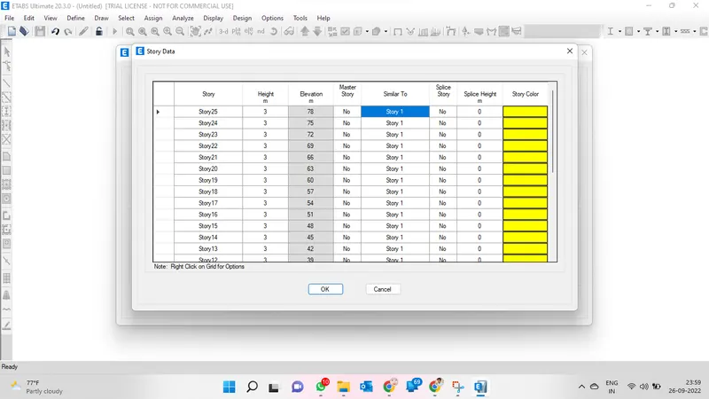
- The following Display will lead on screen after completing the process of editing grid and story height
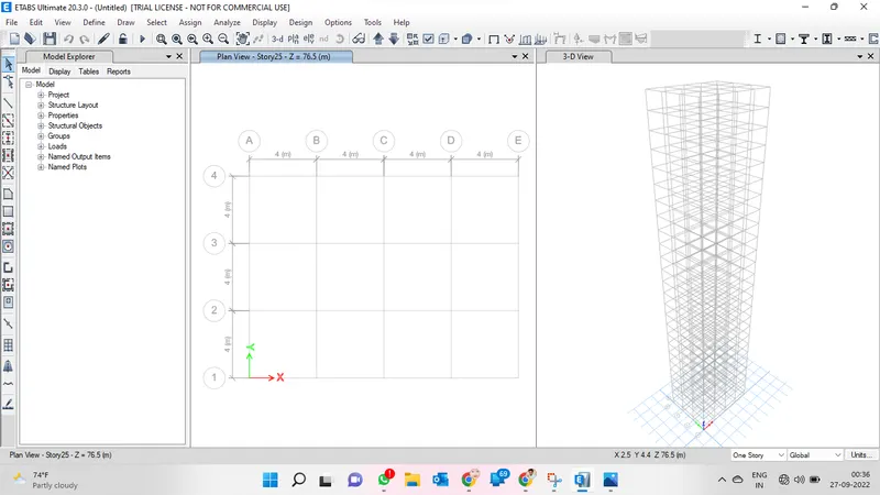
- After this we have to define the material,section properties etc
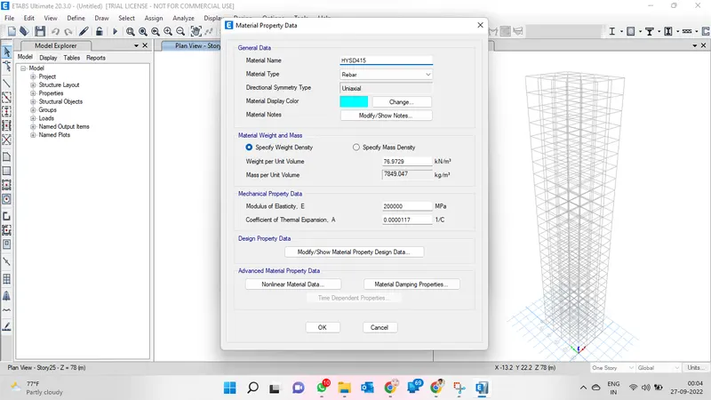
- Choose define >> Material properties and the followig box apppears
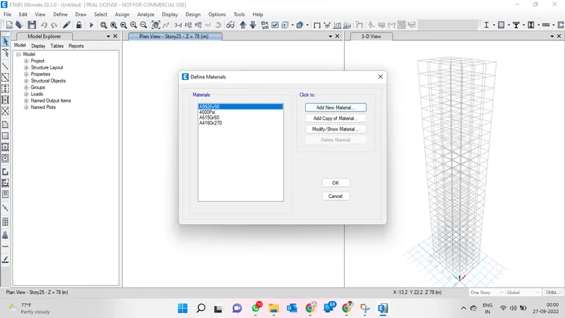
- From the box,Choose add new Material and change the datas repectively for the concrete,Rebar respectively as shown below.
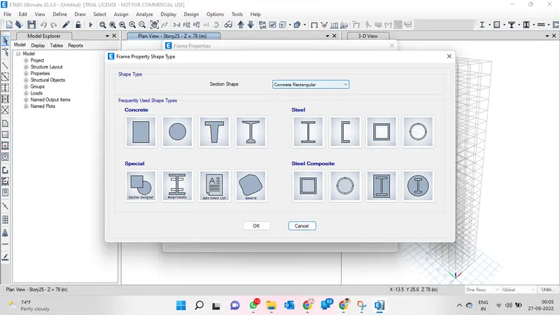
- Choose Define>>Section Properties>>Frame sections ,Choose rectangular Concrete from it
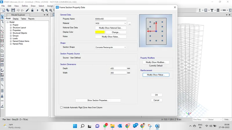
- The following Box Appears and change the repective data for beam,Its size,material,depth and width as shown below
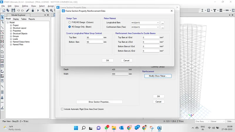
- Choose Modify shear rebar option and change the material as HYSD fe415 as Shown below
- From the frame section option choose concrete and Edit for column this time,Change the data with respect to size,material ,width and breadth as shown below
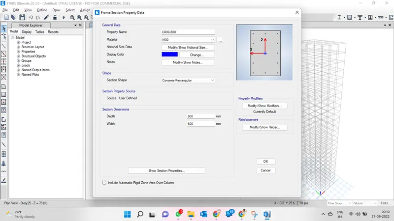
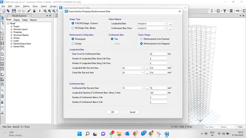
- Choose Modify Shear rebar and change the datas over there and enter ok as shown below
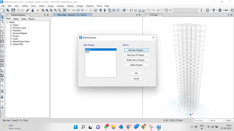
- Choose define >> Section Property>> Slab Sections and the following box appears
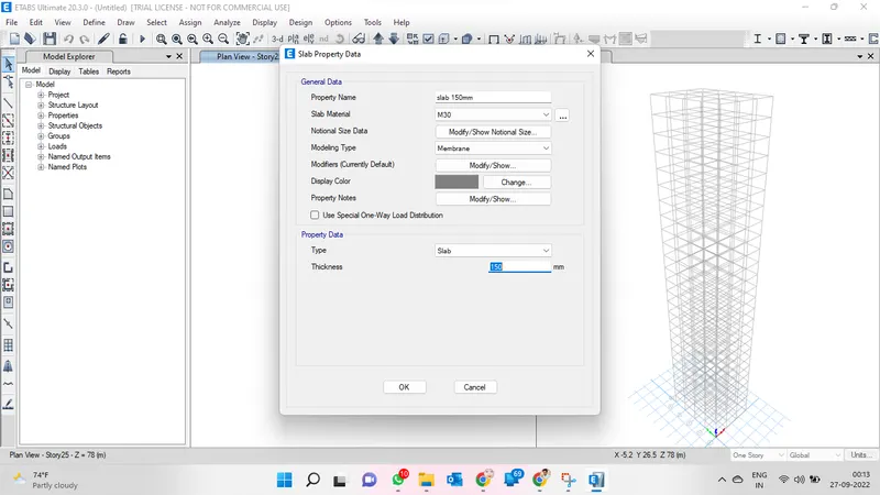
- Choose add new Property and edit the name,material,Tickness and Type as shown below
- Choose DEFINE>>LOAD PATTERN and the following box appears
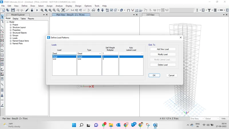
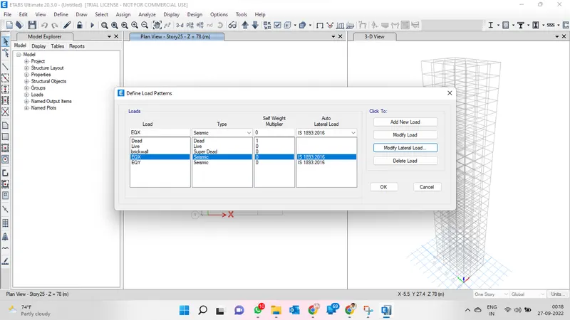
- Enter the repsective loads and proceed further as shown
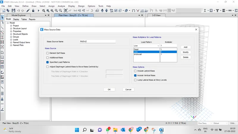
- Choose Define >> Mass source and enter the loads presentoverthere as shown below
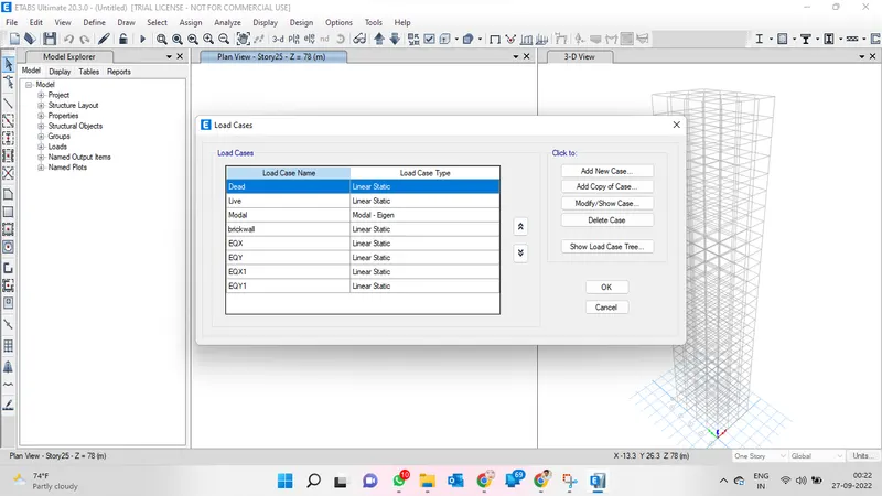
- Choose define>>Load cases and verify the loads present in it as shown below
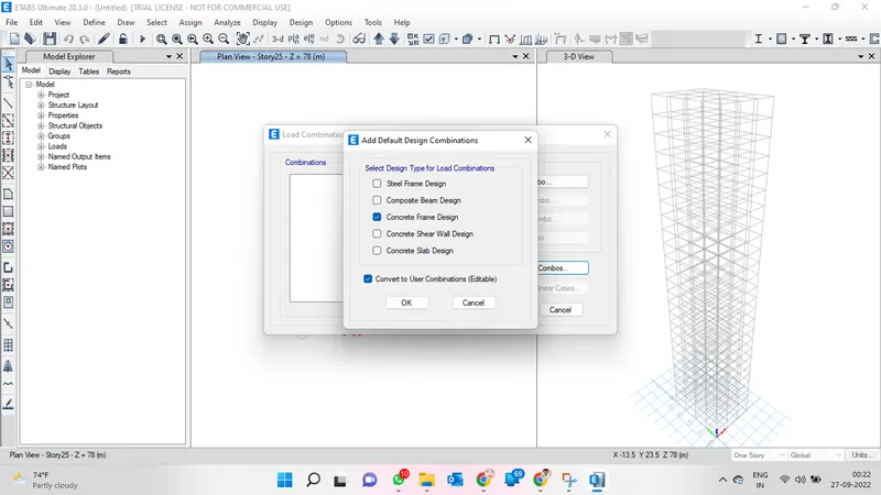
- Choose define>>Load Combination and choose default combofrom it as shown below
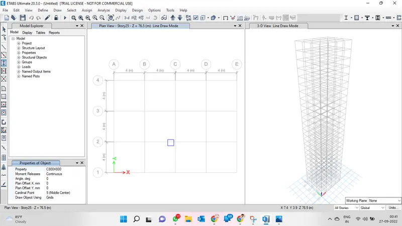
- Using Quick draw column tool change the property and single story to all story and place the column
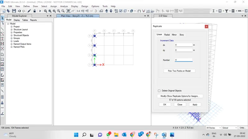
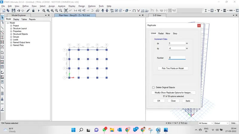
- After Placement of column along one side choose cntrl+R for replicateand replicate the column on nearby axes
- Using Quick draw beam tool change the property and single story to all story and place the column and replicate it using the option as shown below
- Using Quick draw Slab tool change the property and single story to all story and place the column as Shown below
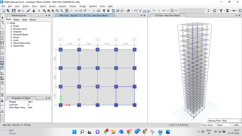
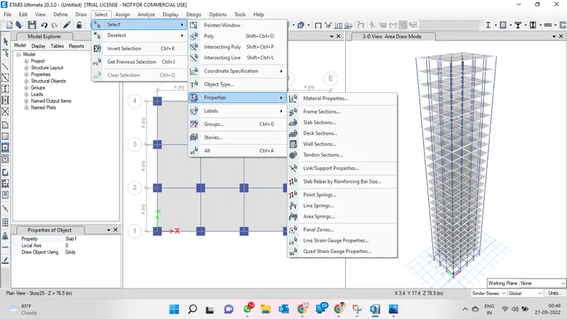
- Select the Beam and then Choose Select >> properties>>Frame sections
- Apply the dead load as 10KN as showm below
- Select the slabs and Choose Assign >> Shellload >> Uniform and APply the load value mentioned
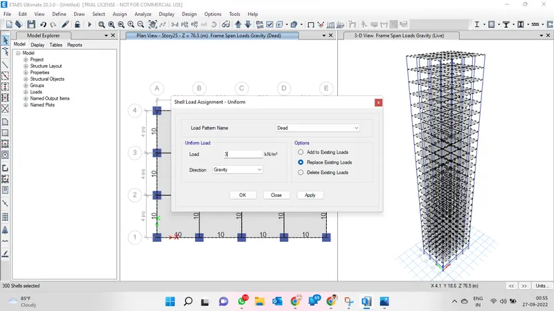
- the Slab seems to be in this manner after applying the loads as given below
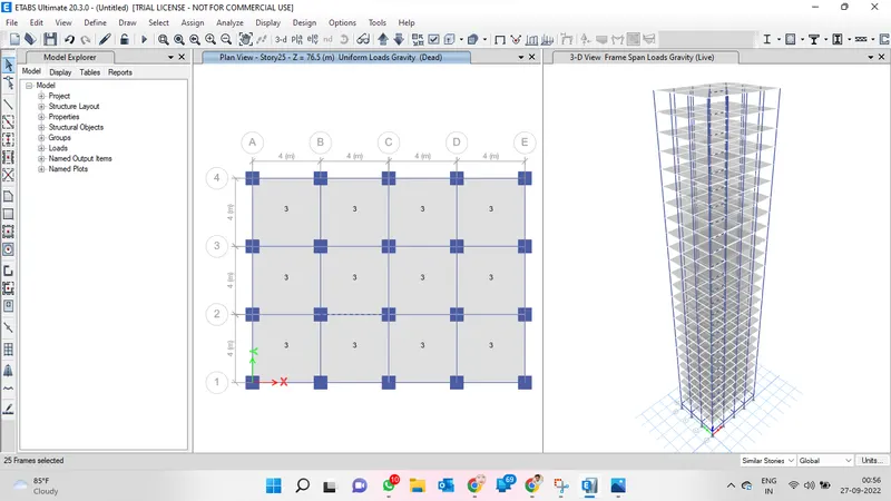
- Choose Assign>>Shell>> Diaphgram the followuing box appears.
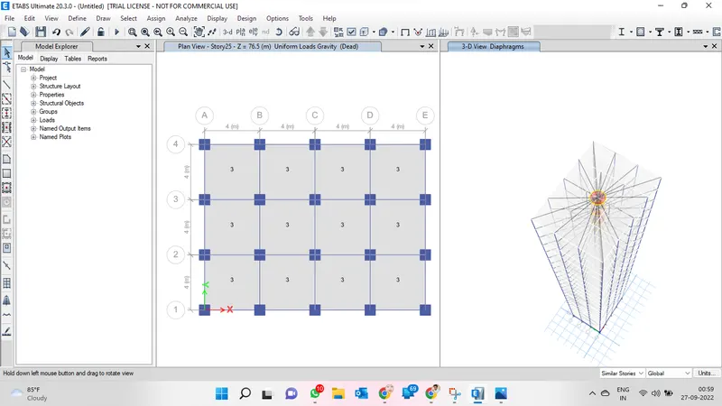
- Now run the analysis.
- using table option at the left we can analyze the table as shown below
- 1)Check if the translational fundamental natural period of vibration in both the x and y direction is approximately: Tx1Tx1= 4.4 second Ty1Ty1= 4.2 second
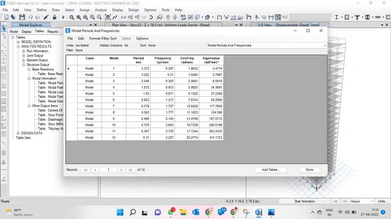
- From the table it is clear that tx1 = 3.37 and tx2 = 3.225 nearer to our value
- 2) Check if the following provision in Table 5 of IS 1893 (part 1) – 2016, on torsional irregularity satisfied:
- The above condition means the mode 3 should be lesser than mode 1 and 2 . which is also satisfied from the table
- 3)Check if the two provisions of clause 7 in Table 6 (shown below) of IS 1893 (part 1) – 2016, regarding vertical irregularity is satisfied
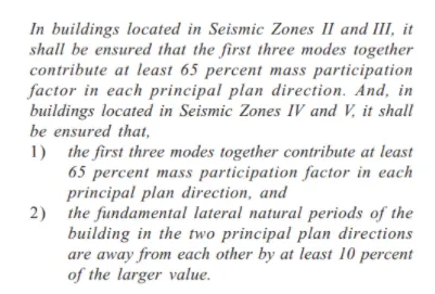
- 2)-1 From the below table it is clear that 1st mode itsel is greater than 65% and it satisfies the codal provision
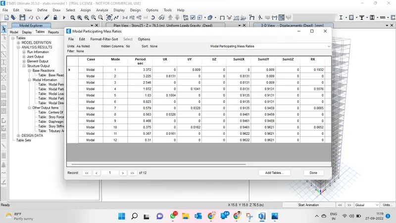
- 2)-2 The first Modal we have 3.372 Multiplying it by .9 we get 3.03 the second modal that has been arrived is 3.22 the condition doesnt satisfies in this case
- 3)-Check if provision on inter-storey drift limitations in clause 7.11.1.1 satisfied. Please note that this check is for Serviceability Limit State and hence is for situation when stucture is subjected to unfactored seismic base shear
-
Choose Display>>story response plot as shown below
-
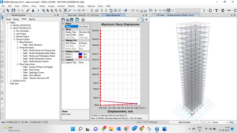
- Change the laod type into eqx and eqy and observe the deflection
- Both are less than .004 and proves it satifies the codal provision
Result: From the above proceudre we come to know how design 25 story building and assigjn the properties,apply load and run the analyse and also we are also able to check the Structure output of the plan