Modelling of 25 storey building with the specified properties using ETABS
1)
AIM:
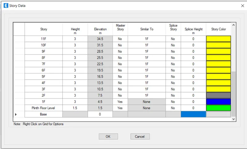
To model a 25 storey building on ETABS with structural properties as specified below. Ground floor or plinth floor level can be taken at a height of 1.5 metres from the base. Each of the successive 25 storeys has a storey height of 3 metres.
GIVEN:
Structural Element Sizes
- Beams : 300 × 400 mm
- Columns : 800 × 800 mm
- Slab : 150 mm thick
Material Properties
- Grade of Concrete : M30
- Grade of Steel Reinforcement Bars : Fe 415
Loading
- Dead Load on beams from infill wall : 10 kN/m (Let us assume the same for roof floor in view of parapet)
- Live load on floor : 3 kN/m2 (Let us assume the same for roof floor)
a) Buildings are assumed to be pinned at the base
b) All columns in all storey are of the same size
c) All beams in all storeys are of the same size
d) Building is located on Soil type-II and in Zone-III. Assume other factors if required.
Carry out the following exercises:
- Check if the translational fundamental natural period of vibration in both the x and y direction is approximately: Tx1">Tx1 = 4.4 seconds Ty1">Ty1 = 4.2 seconds
This check will help confirm if modelling is done correctly. Some deviations from the above values is possible (± 2%). But any major deviation will suggest an error in modelling.
- Check if the following provision in Table 5 of IS 1893 (part 1) – 2016, on torsional irregularity satisfied:
The natural period corresponding to the torsional mode of oscillation must be less than the two fundamental translational modes of oscillation along each principal plan directions.
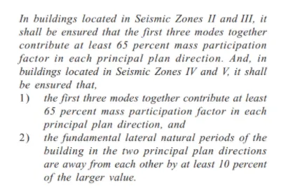
- Check if the two provisions of clause 7 in Table 6 (shown below) of IS 1893 (part 1) – 2016, regarding vertical irregularity is satisfied.
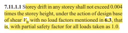
- Check if provision on inter-storey drift limitations in clause 7.11.1.1 satisfied. Please note that this check is for Serviceability Limit State and hence is for situation when stucture is subjected to unfactored seismic base shear
PROCEDURE:
- Open ETABS software.
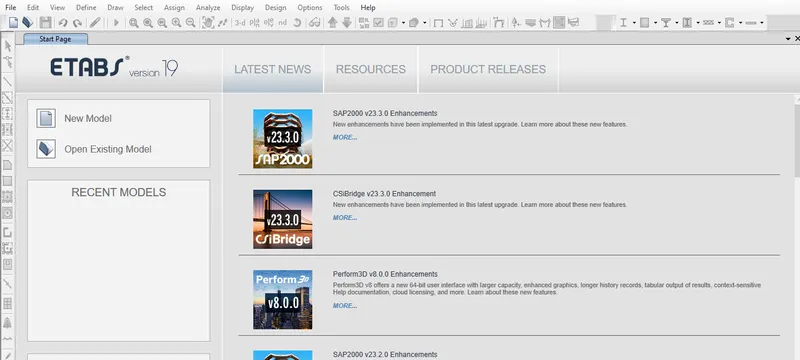
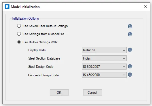
- Click on New Model, a Model Initialization option will pop up. Select Indian Design Codes for Steel and Concrete Design as shown in the below figure.
- Then a new window will pop up , New mode quick template,now input the grid dimensions and storey dimensions by choosing the custom grid only option as shown in the below figure.
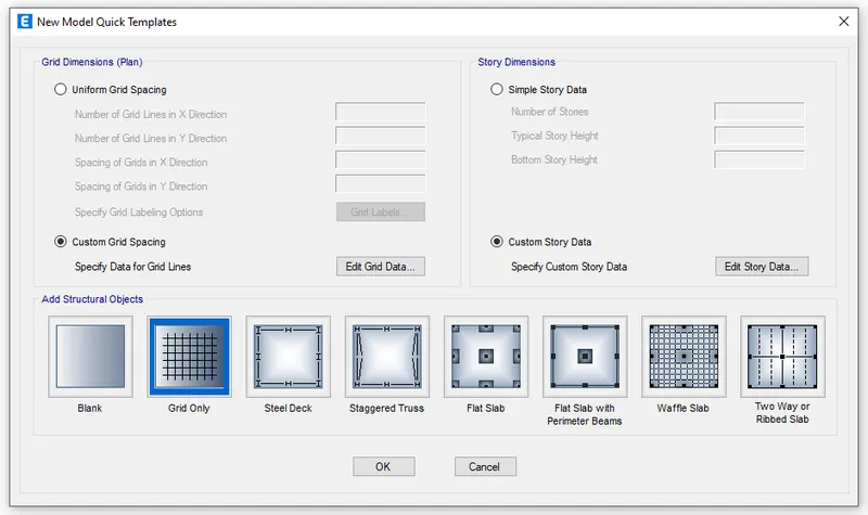
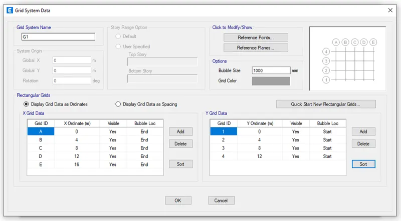
- Now, input the grid dimesions as given in the question.
- Also input storey dimensions.
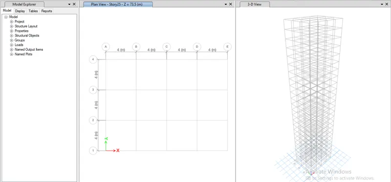
- Both grid and storey details have been filled.
- Now input the material property. Go to define tab and select material properties and then go to add material option in that window.
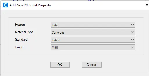
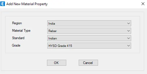
- Hence, the Concrete, HYSD500 and HYSD415 materials are added. Now, click ok.
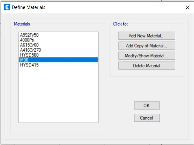
- Now, we need to add the frame members, i.e beams, columns and slabs.Follow the below steps to add respective members:
- Go to Define tab.
- Then to Section properties.
- And select frame sections (beams and columns)
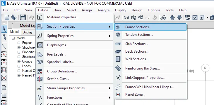
- Frame section property data window opens and then add new material property.
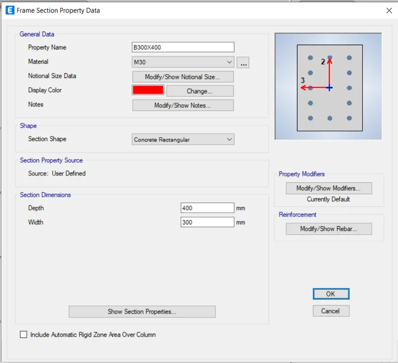
- Reinforcement details and cover to the reinforcement are also provided.
- Similarly, add columns to the list by providing the reinforcement details.
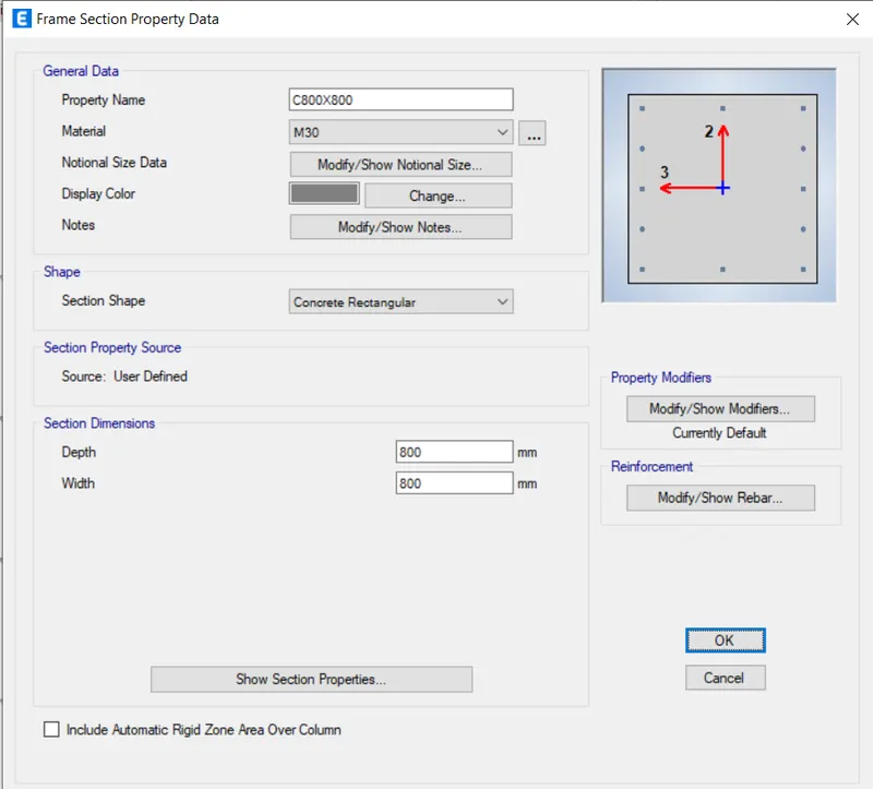
- Hence, the Beams and Columns are added to the list is as given below:
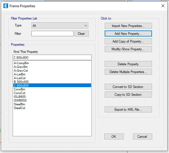
- Next we have to add the slab details.
- Go to define tab.
- Then to Section property and then select slab sections.
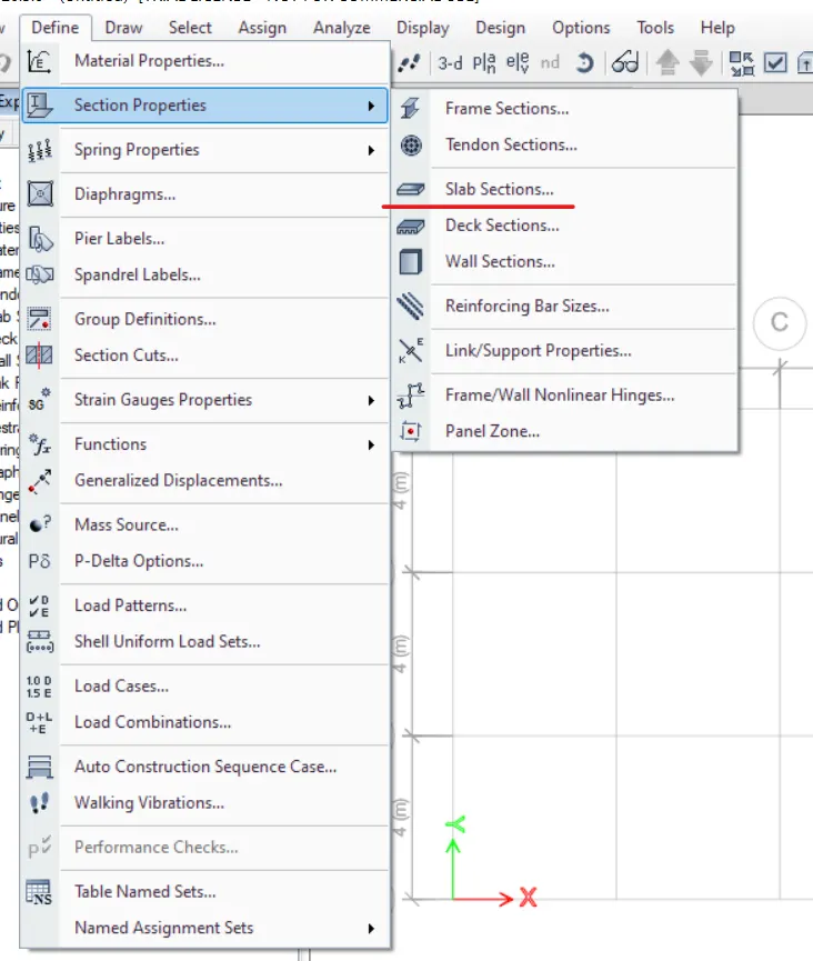
- Slab property data dialogue box opens.
- Now edit the slab properties.

- As all the properties of frame members have been added, now we have to place the structural members.
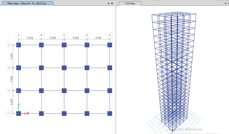
- For this choose quick draw column option from the tools availabe on the left side of the screen and place the columns at all the grid intersections.
- Since columns extends throughout the height of the structure, care should be taken to check whether the columns are assigned to all storeys or not.

- Next, we have to place beams in the position, use quick draw beams option.
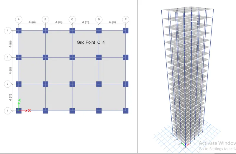
- Now, we have to create the slabs, initially change all the storeys option to similar storeys which may exclude the base.
- Then, choose quick draw floor or wall option to easily draw the floor slabs.
- Now assign loads to the frame.
- Go to define tab.
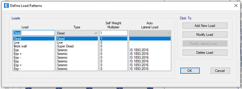
- Then to load patterns.
- Define load patterns dialogue box appears as shown in the figure.
- Then, apply the loads.
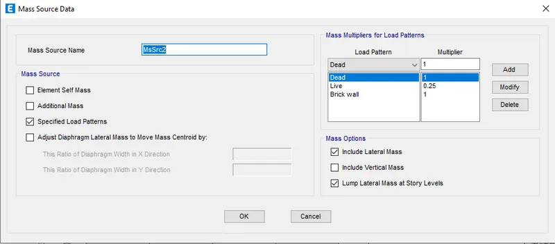
- Now, provide the mass source value to calculate the seismic weight in the mass source data dialogue box as shown below.
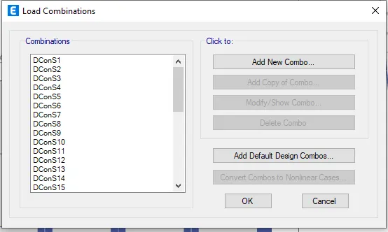
- Next, define the load combinations.
- For this, go to define.
- Then click on Load combinations.
- Provide the default load combination.
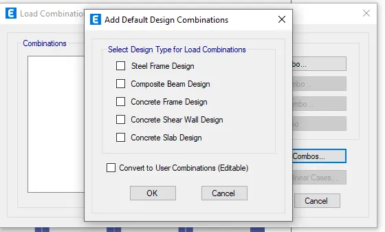
- Choose Concrete frame design and click ok.
- Select all the floors.
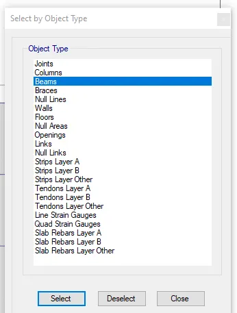
- Go to Select.
- Select object type then floors.
- Then go to assign.
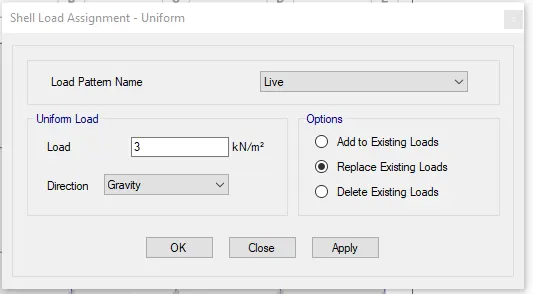
- Select shell loads then Uniform.
- Then apply 3kN/m2
- Apply and click Ok.
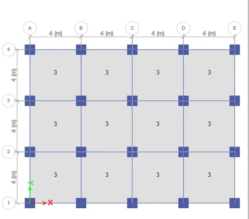
- Select all the floors.
- Select object type then Beams.
- Hence all the beams are selected.
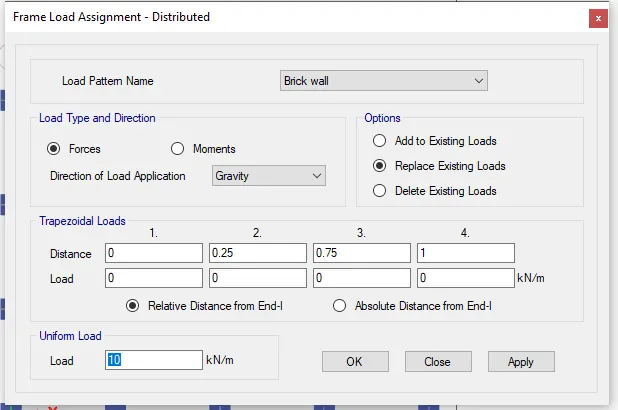
- Then go to assign and click on Frame loads then distributed then load pattern - Brick wall load and type load as 10kN/m
- Apply and then ok.
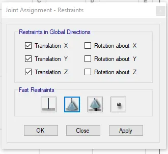
- Add the pin support, for this select all joints by keeping in view the base storey.
- Then Go to assign and then joint and then click on restraint and then select pinned joint.
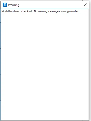
- No, go to analyse tab and check model, it is checked for any errors and warnings in the model.
- Analyse the model.
- Go to analysis.
- Run analysis.
- Hence, analysis has been completed.
- Now, we need to check the details given in the question.
- Initially go to display tab.
- Click on Show tables.
- Then Analysis result.
- Then Structure output.
- Then Modal information.
- Then Modal periods and frequencies.
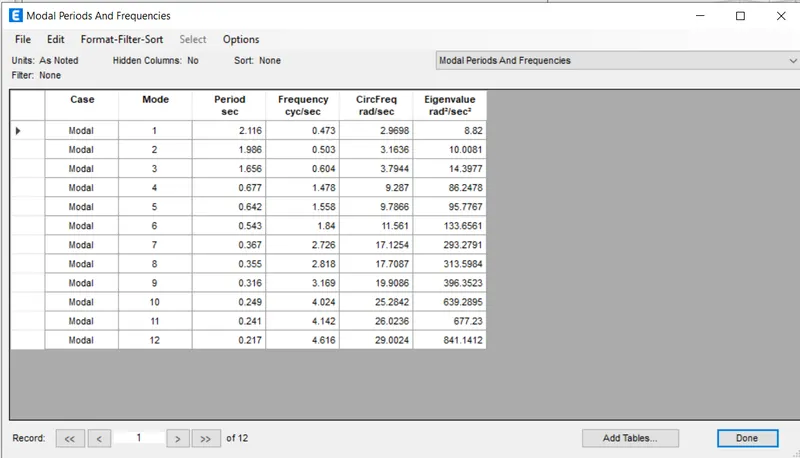
- Check for translational fundamental natural period of vibration in both the x and y direction:
-
1st mode corresponds to translation in y direction, hence Ty1 = 2.116 s
-
2nd mode corresponds to translation in x direction , hence Tx1 = 1.986 s
-
- Check for the following provision in Table 5 of IS 1893 (part 1) – 2016, on torsional irregularity satisfied:
- The natural period corresponding to the torsional mode of oscillation must be less than the two fundamental translational modes of oscillation along each principal plane directions.
- The natural period corresponding to two translational modes of oscillation is obtained as:
- Tx1 = 1.986 s
- Ty1 = 2.116 s
- The natural period corresponding to the torsional mode of oscillation is obtained as:
-
Txy1 = 1.656 s
-
- Hence, it is verified that the natural period corresponding to the torsional mode of oscillation is less than the natural period corresponding to two translational modes of oscillation.
- The natural period corresponding to two translational modes of oscillation is obtained as:
- Now, modal participation ratios have to be taken, for this go to display tab then click on Show tables and then Analysis result then Structure output then Modal information and finally click on Modal participating mass ratios.
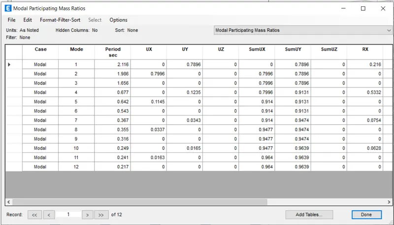
- Check if the two provisions of clause 7 in Table 6 of IS 1893 (part 1) – 2016, regarding vertical irregularity are satisfied.
- Modal mass participation ratios of first three modes in X direction is obtained as obtained are:
-
- 1st = 0.216
- 2nd = 0.7996
- 3rd = 0
- Summation of these three we get, 0.216+0.7996+0 = 1.0156 >100% > 65% .
- Hence it satisfies the code which says i.e, "the first three modes together contributes atleast 65% mass participation factor in each principal plan direction".
- Now, the difference between X and Y time period is given by, 2.116-1.986 = 0.130 >≈ 6.14%.
- Hence, it does not satisfy the code which says , "the fundamental natural periods of the two buildings in the two principal plan directions are away from each other by at least 10% of the larger value".
Result:
The analysis of the 25 storey building is completed and the specified checks are also carried out. The structure satisfies all the codal provisions except the second provision of clause 7 in Table 6 of IS 1893 (part 1) – 2016, regarding vertical irregularity, which is given as, the fundamental natural periods of the two buildings in the two principal plan directions are away from each other by at least 10% of the larger value.