Modelling of 25 storey building with the specified properties using ETABS
AIM:
Modelling of 25 storey building with the specified properties using ETABS
INTRODUCTION :
objective of the challenge to know modelling of high rise building in ETABS software and to verify the seismic code requirements from ETABS analysis.
PROCEDURE :
STEP-1
- open ETABS software
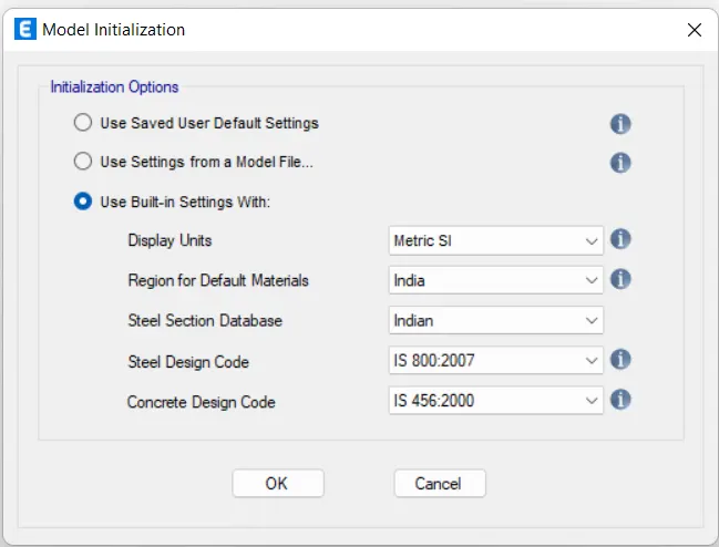
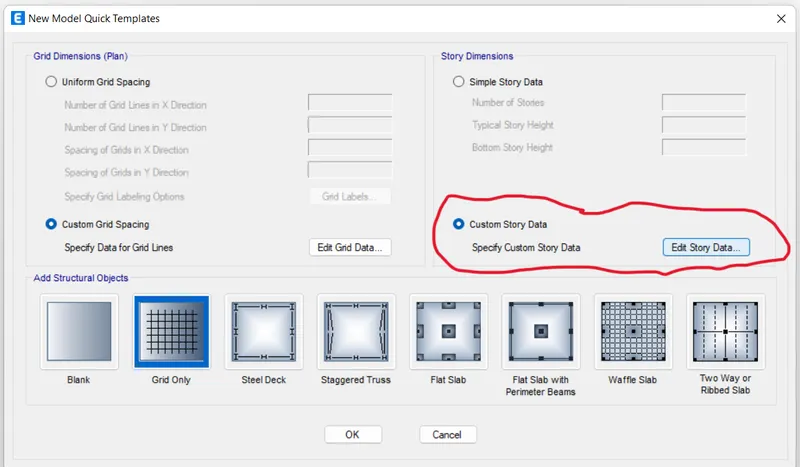
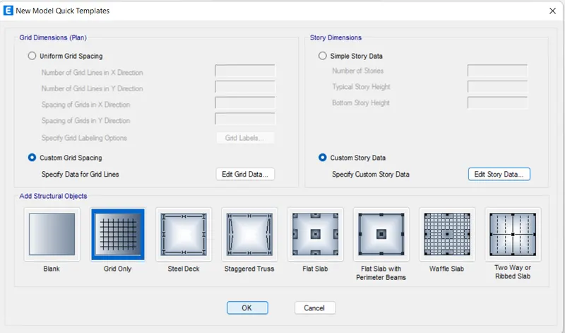
- select new model > select use built in setting with
- set parameter as shown in image
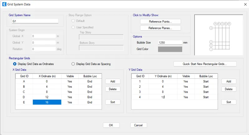
- select custom grid setting and select edita data
- edit the grid system data as shown in image
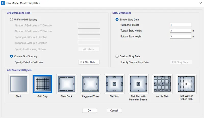
- select custom story data > select edit story data
- edit story data as shown in image
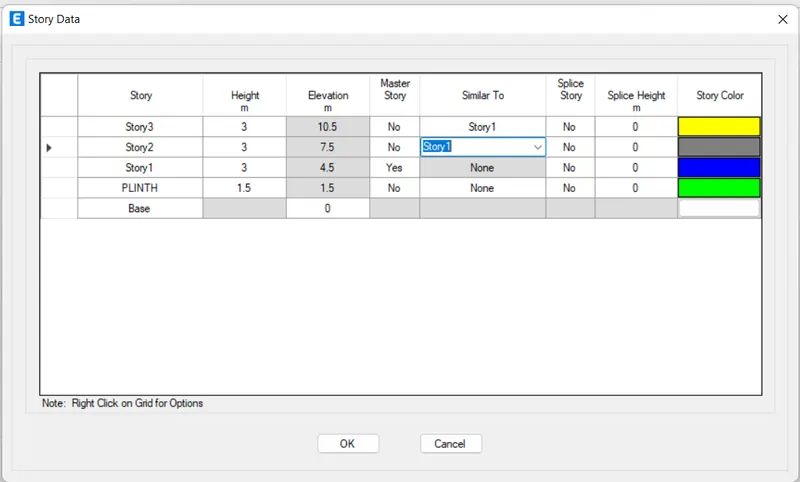
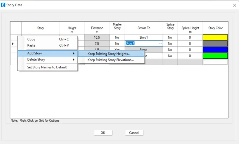
- we need to make 25 story building so that we need to add story
- right click of mouse on story 3
- select add story then select keep existing story height
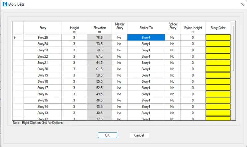
- type22in add story as 3 story already created
- press ok and following table will appear then select ok
- now select grid only from model quick template
- press ok
- following screen will appear
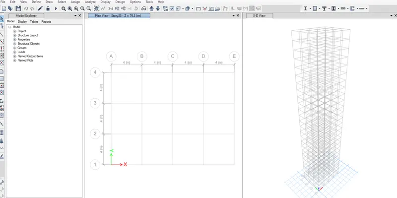
STEP-2
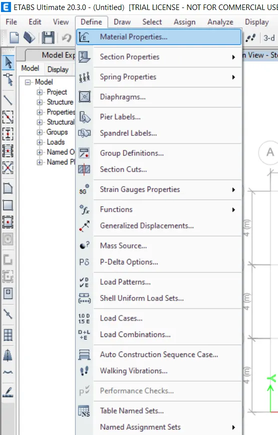
- go to define tab > select material properties
- select add new material
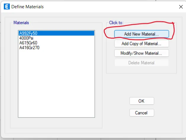
- edit add new property for concrete
- region-India, material type-concrete, std-indian, grade-M30
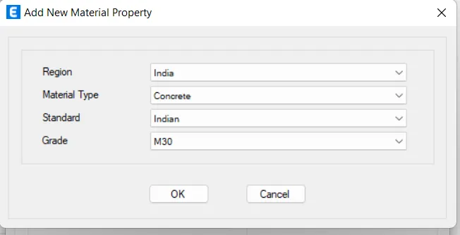
- press ok and edit table as shown in image
- material name as M30
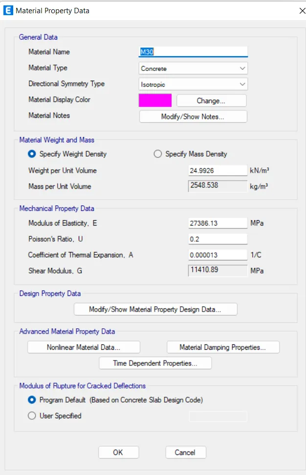
- press ok
- edit add new property for rebar
- region-Idia, material type-rebar, std-Indian, grade-HYSDgrade415
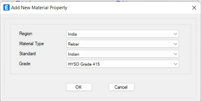
- material name-HYSD415
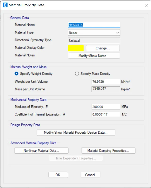
- press ok
STEP-3
- go to define tab > select section properties > select frame section
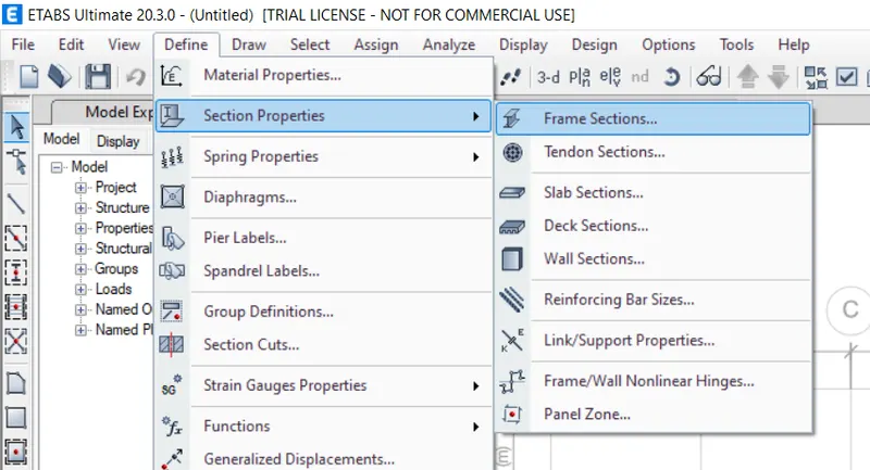
- select frequently used shape type > concrete> rectangular section for beam
- 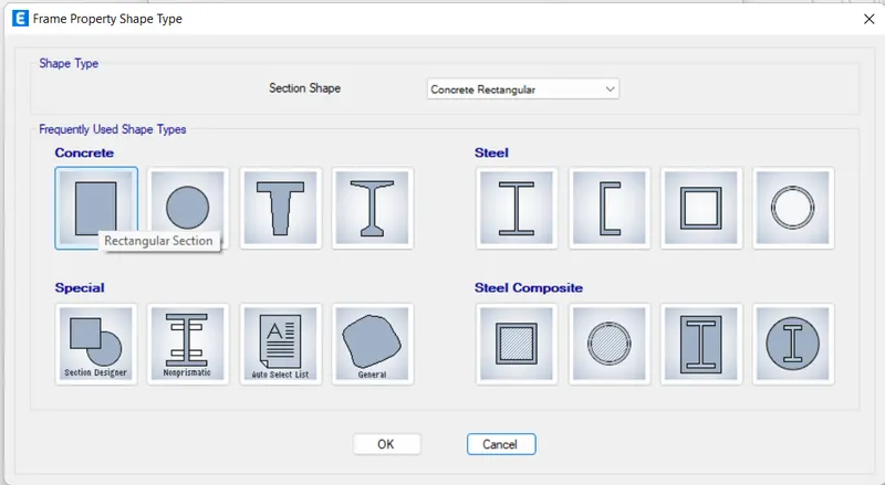
- frame section property table will appear
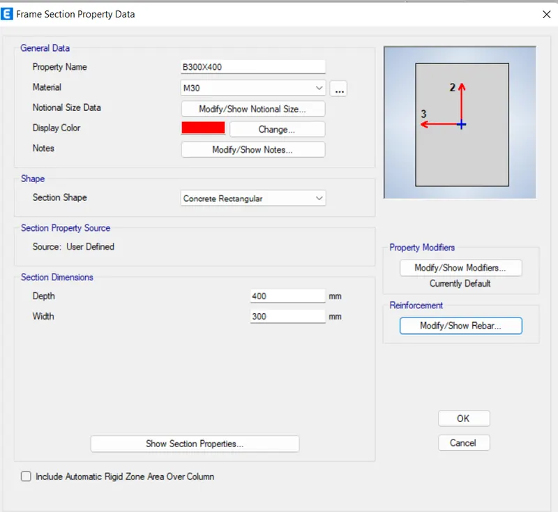
- type property name as B300x400
- type depth-400 and width-300
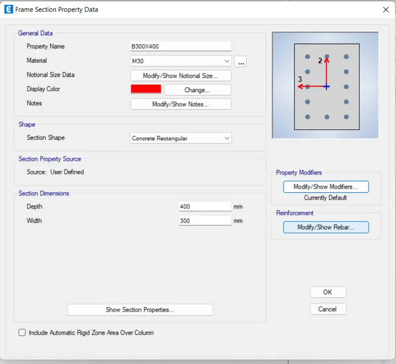
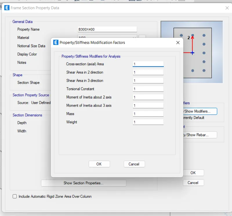
- select property modifier
- here keep the value of moment of inertia 1, usually for eq design we used 35% but it is applicable in ultimate design
-
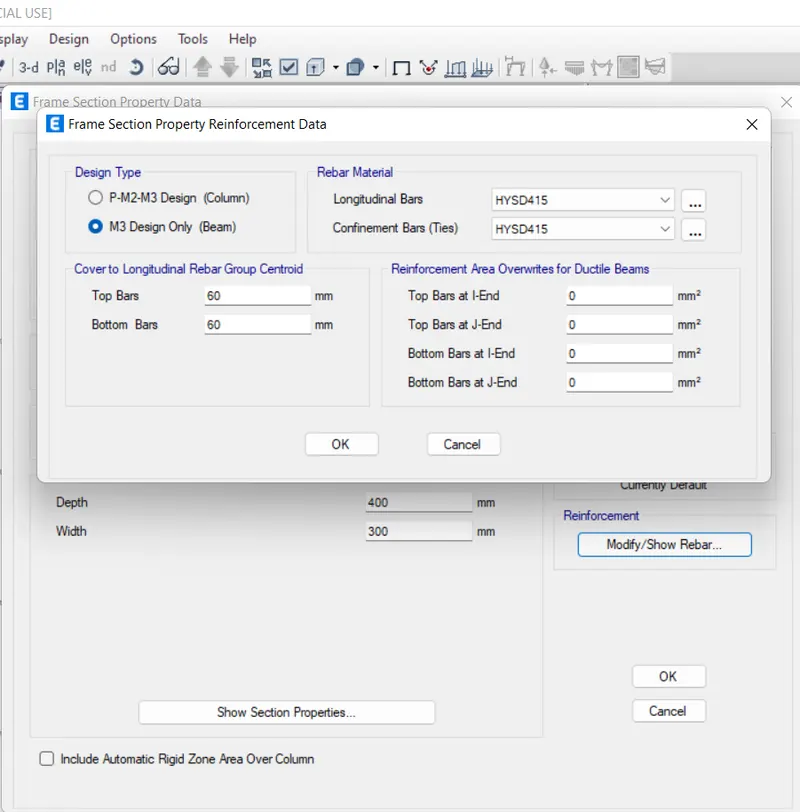
- select modify show rebar
- select m30 desgin only for beam
- press ok
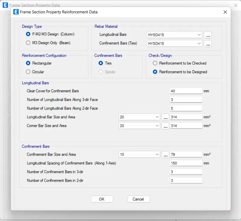
- select again add material for column design
- follow the similar procedure as we done in above step
- except select frame section properties as P-M2-M3 design for column
STEP-4
for slab
- go to define tab > select section properties > select slab section
- edit the property as shown in image

STEP-5
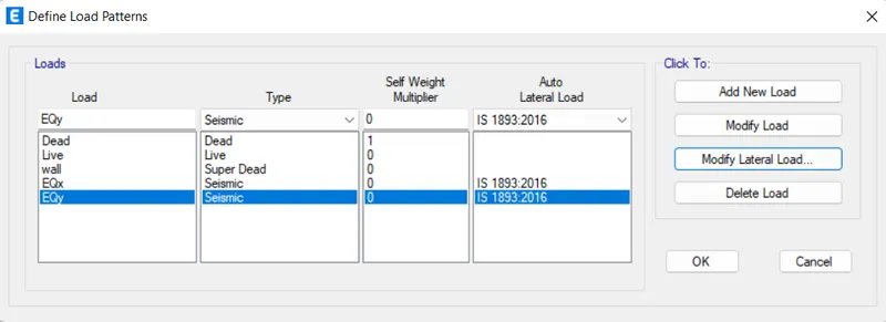
- load pattern
- go to define tab > select load pattern
- add load > wall load, eqx load, eqy load
-
- press ok
STEP- 6
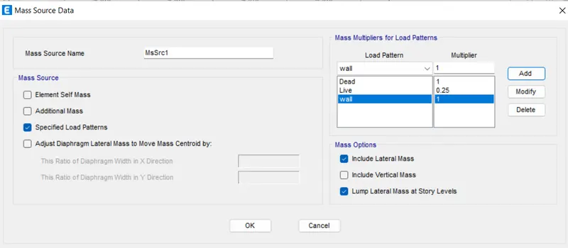
- Select mass
- mass should be considered for seismic lateral movement
- go to define tab > select mass source
- select modify/show mass source
- select speified load patterns
- considered deal load as 100%, LL-75%, wall load or super DL-100% as per code
- press ok
STEP-7
- check for load cases as we assign properly or not, go to define tab > select load cases
- go to define tab > select load combination
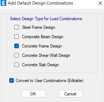
- select add default design combo
- select following properties and press ok
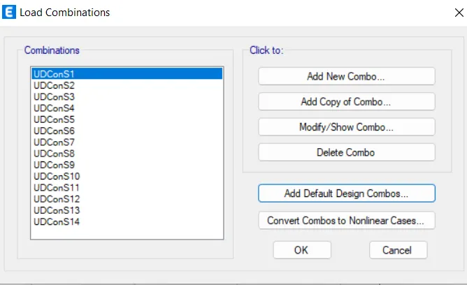
- press ok
STEP-8
COLUMN
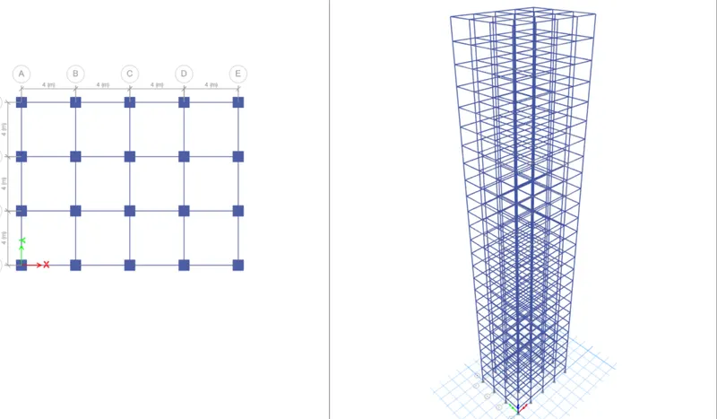
- select quick draw column from left side column
- at bottom left properties object will open
- Select all stories
- select property-C800X800
- and draw column on grid points
- first i have draw column on y axis and then by using replicate option we have drawn other remaining column on grids.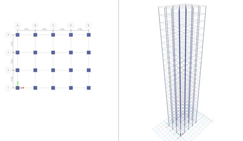
BEAM
- now select quick beam drawn option
- in properties object > select property- B300X400
- select all stories
- MARK the beam on top most x-axis
- mark the beam at left most y-axis
- then by using replicate option draw other beams on x and y direction
SLAB
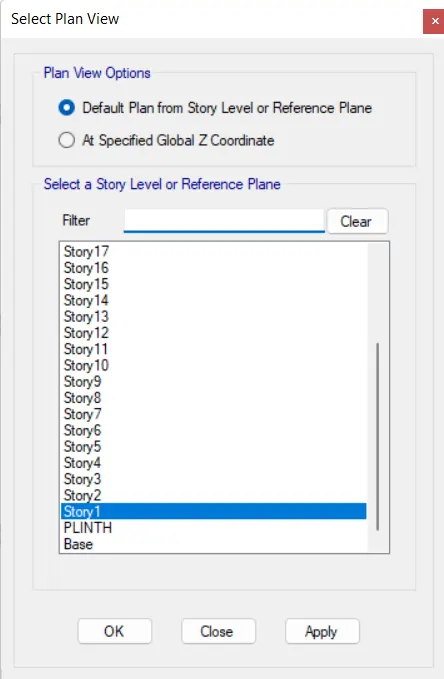
- select select object > go to set plan view to story 1
- select similar story not all stories

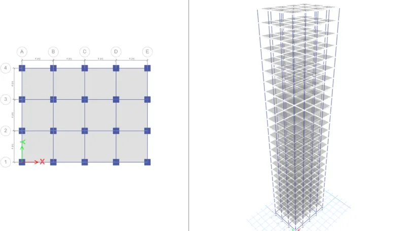
- select properties object
- select property > select S150
- assign slab in map
STEP-9
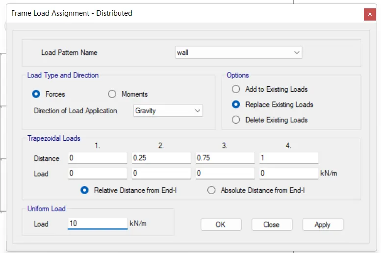
- select frame section
- go to select tab > select properties > select frame section > select B300x400
- go to assign tab > select frame loads > select distributed
- load pattern name - type wal, uniform load - type 10kn/m as given
- press ok
- now select slab section
- go to select tab > select properties > select slab section > select S150
- press ok and close
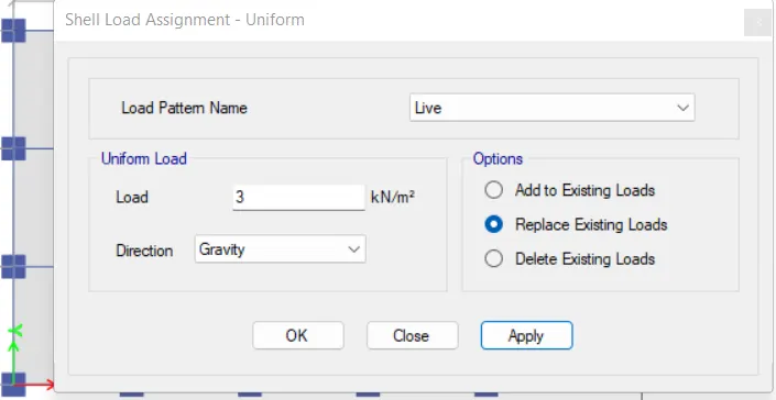
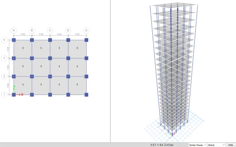
- go to assign tab > select shell loads > select uniform
- load pattern name- select live, select load -3kn/m^2
press apply and ok
- select slab section again
- go to select tab > select properties > select slab section > select S150
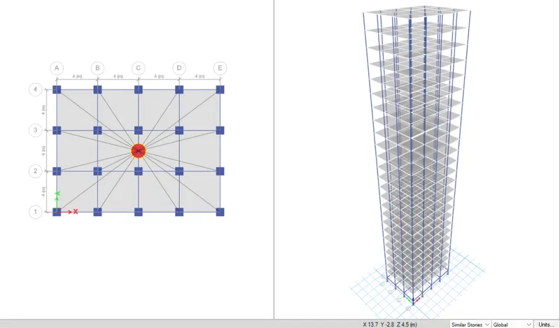
- go to assign tab > select shell > select diaphragms > select D1> select apply ok close
STEP-10
- run analysis
- go to run analysis > below the menu tab > you can see play symbol of run analysis
- save the file
- analysis completed
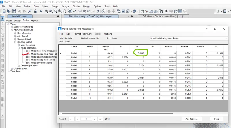
- go to model explorer > select structure output > select model information >select modal periods and frequencies by selecting right click of mouse and then table
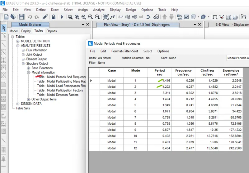
- now go to modal participating mass ratio
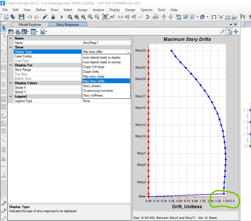
- now go to display command > select story response plot
- select display type - max story drift, case combo-EQx
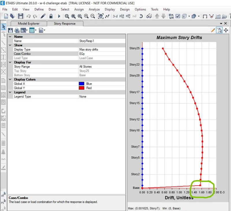
- now select case combo EQy
RESULT :
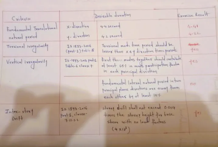
we have created ETABS modelling of a 25 storey building and the result obtained as follows