Modelling of 25 storey building with the specified properties using ETABS
OBJECTIVES : To Know modeling of a high rise building using E-Tabs.
AIM: To model a 25 storey building using ETABS with reference of IS 1893
Introduction: ETABS is an engineering software product that caters to multi-story building analysis and design. Modeling tools and templates, code-based load prescriptions, analysis methods and solution techniques, all coordinate with the grid-like geometry unique to this class of structure. Basic or advanced systems under static or dynamic conditions may be evaluated using ETABS. For a sophisticated assessment of seismic performance, modal and direct-integration time-history analyses may couple with P-Delta and Large Displacement effects. Nonlinear links and concentrated PMM or fiber hinges may capture material nonlinearity under monotonic or hysteretic behavior. Intuitive and integrated features make applications of any complexity practical to implement. Interoperability with a series of design and documentation platforms makes ETABS a coordinated and productive tool for designs which range from simple 2D frames to elaborate modern high-rises.
Procedure:
STEP 1
- Open E-Tabs ->new file
- A new tab will open
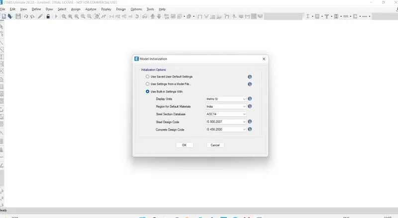
- Use built in settings ->change the units and codes as per indian standard->Click Ok
- A new tab will open
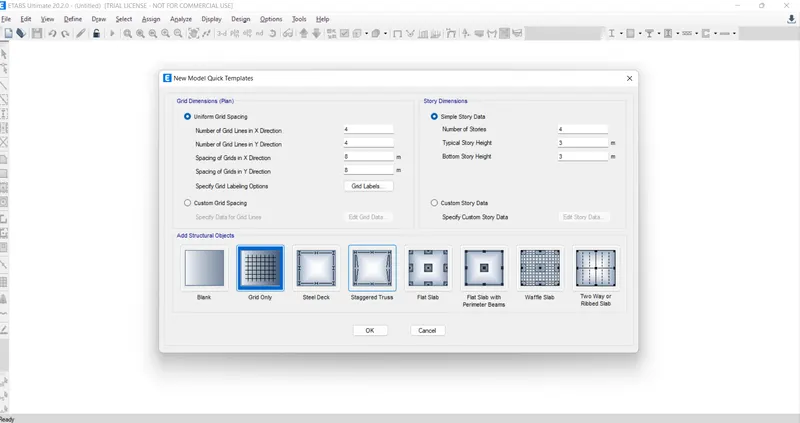
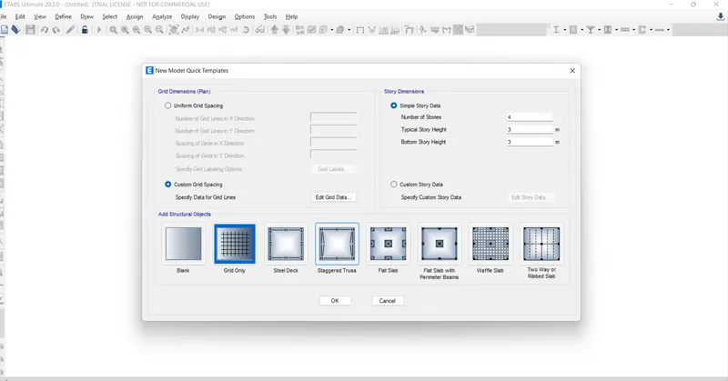
- Click on custom grid spacing Edit grid data
- A new tab will open.
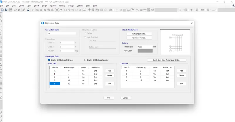
- Enter the grids ordinates in X direction And Y direction
- Click on Add to made more grids as pers requirement Click on Ok
- You will be brought back to the previous pagE
- Click on custom storey data->A new tab will open.
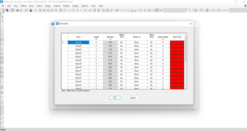
- Right click on and select "add new story"->Enter number of story you want->enter distance between them
- Select story 1 as the master story and all athers as No(as shown in the above pic)
- Select siimilar to "Story 1"->SO that all other story will be similar to story 1
- Click Ok.
STEP 3:
- Will be taken to template page->click Ok
- The main page will open showing the building structure you designed shown below.
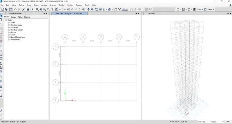
STEP 4
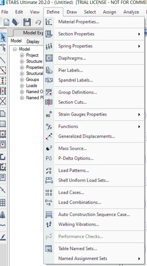
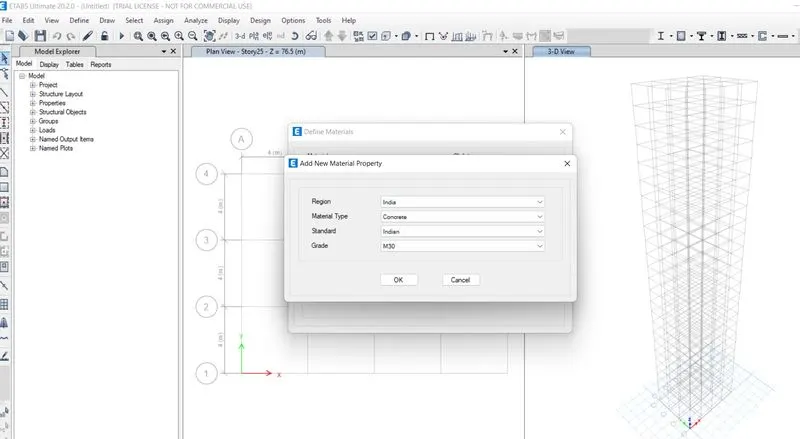
- Click on Define bar->material properties->a new tab open
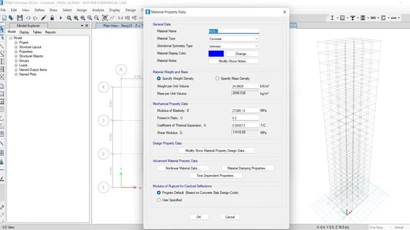
STEP 6
- Next we need to add rebar as the material.
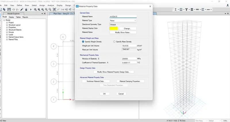
step 7:
- After adding the material properties.
- we have to add the column and beams sections
- Go to define
- section properties
- frame sections
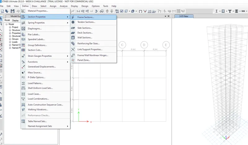
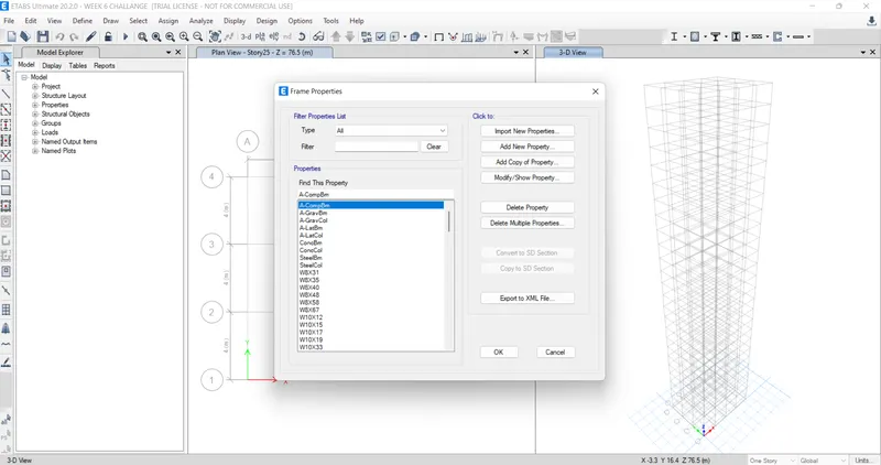
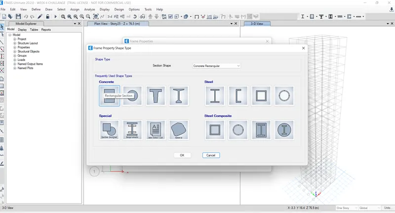
- Next a frame section property data will open->you have to enter the data for the beam and columns
- Change the property name as pers given data B300x400->change material in to M30
- enter the depth and width of the sections.
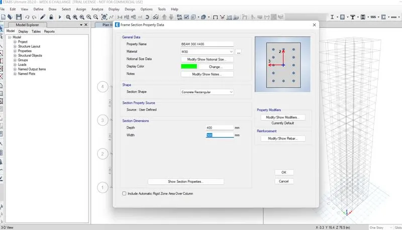
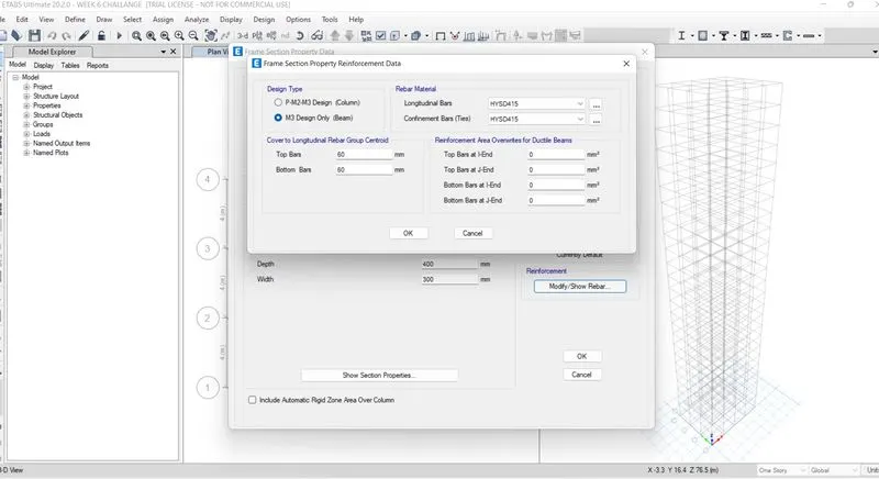
- Click on Modify/show rebar to enter the rebars types and numbers
- A new tab will open click on M3 design only
- Change longitudnal bars Ties bar types to the one you made before
- Enter the covers distance click on OK.
STEP 8:
- Again on frame sections Add new property
- Select the rectangular concrete section click on OK
- A new tab open->rename the property as C800x800
- Enter the width and depth of the column.
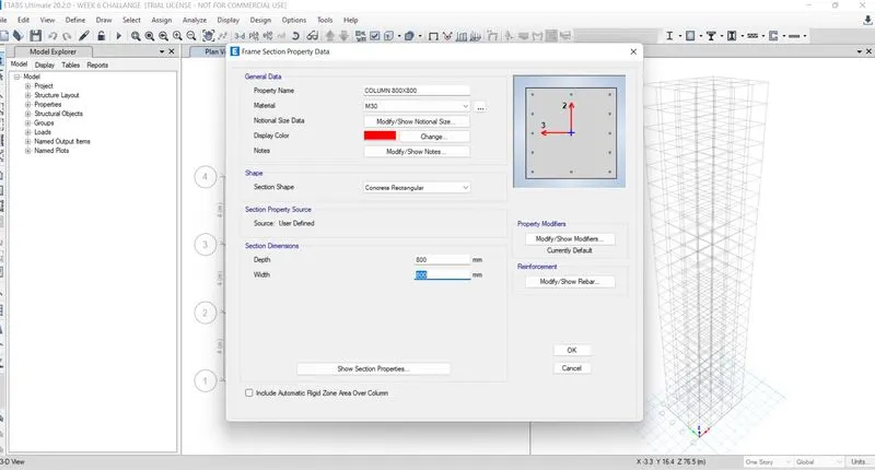
- Click on modify/show rebar to enter the bars type of clumns
- A new tab will open
- click on P-M2-M3 design.
- Enter longitudnal and tie bars type.
- reinforcement to be designed.
- Enter the number of bars your want in 2&3 direction.
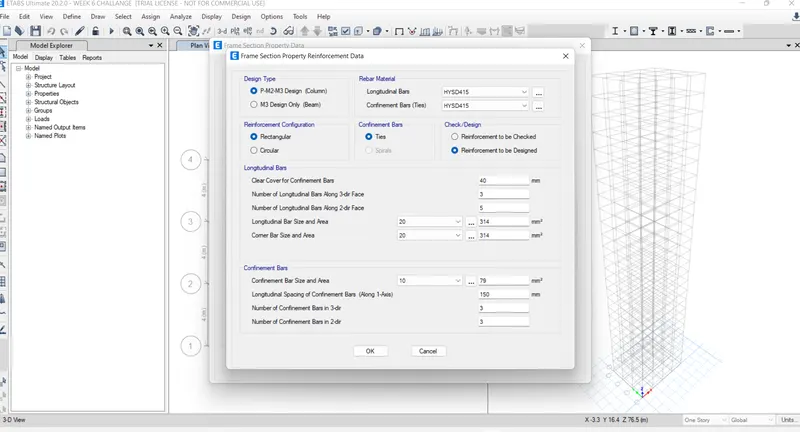
STEP 9:
- Next we select the slab section for the slab of 150mm
- Go to define
- section properties slab section.
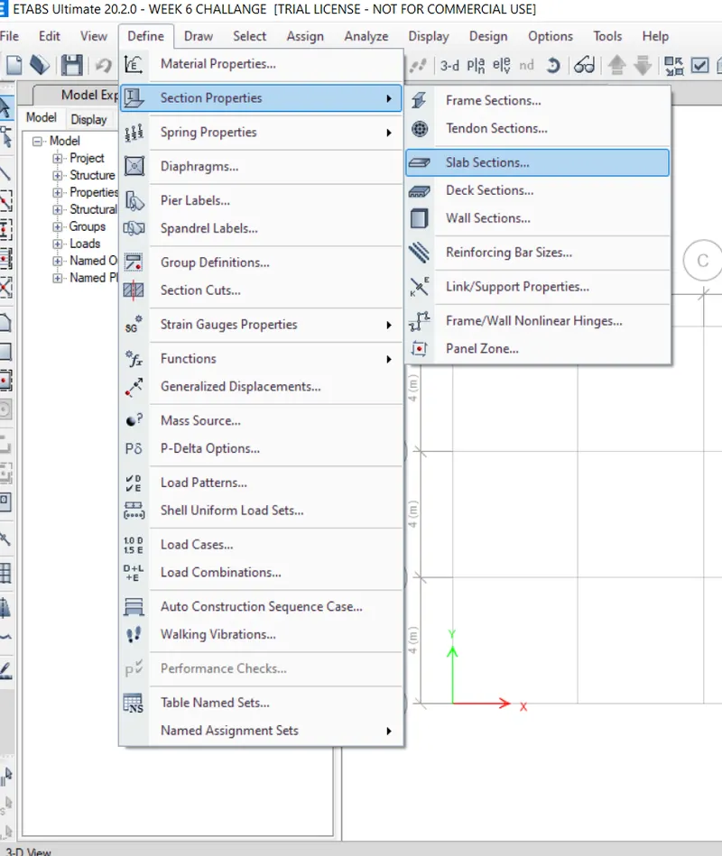
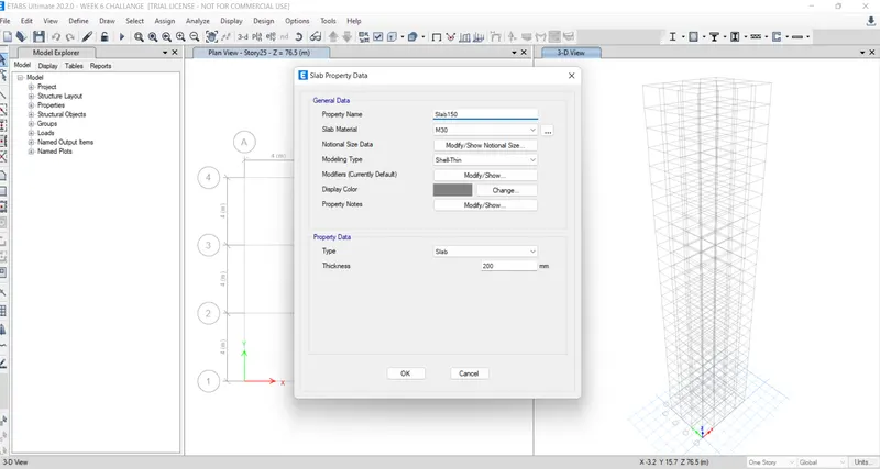
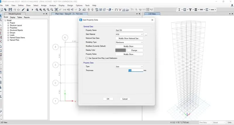
- Now we need to define load patterns->Go to Define Bar "Load patterns"
- Add dead load ,live load,brickwall load and earthquake load as shown.
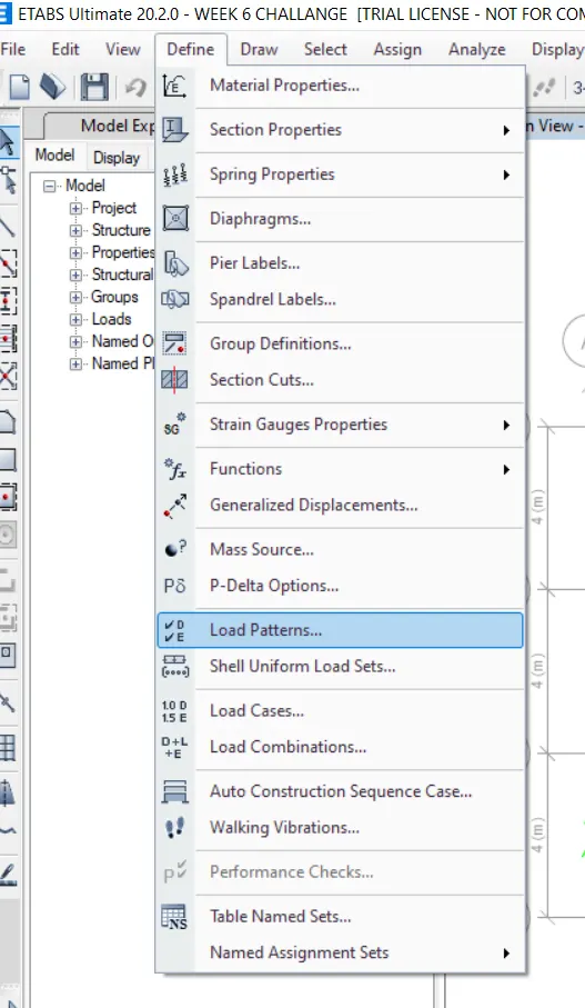
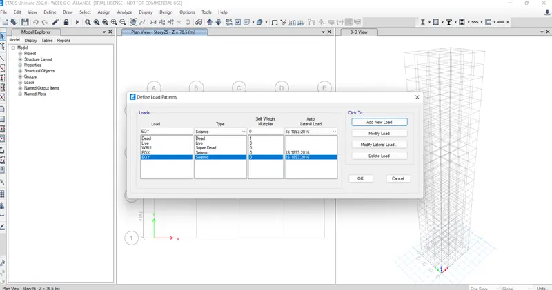
- Now we have to modify the earthquake load as per the direction of applications
- To modify ,click on earthquake loads "EQx-"
- CLick on Modify lateral load
- A new tab will open
- select only the Load direction you want X dir-eccentricity in this case
- Select Site III as suggested in the question & time period user defined 0.5 sec.
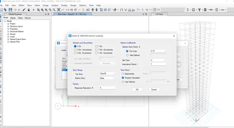
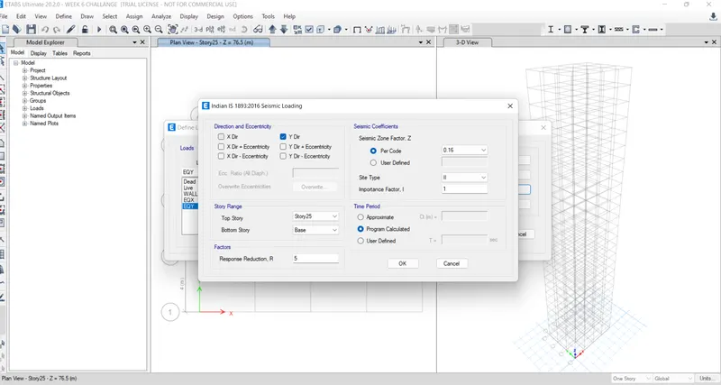
- Now we define mass source
- Go to Assign Menu->MAss source
- A new tab will open->Click on Modify/show mass source.
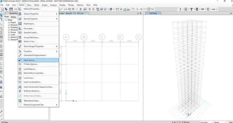
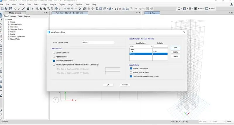
- modify tab will open
- select specified load patterns
- Input dead load=1,
- brickwall-1,
- live load=0.25.
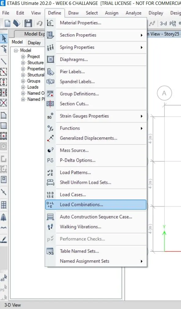
- Now load combination will be defined
- From the define menu->go to load combination
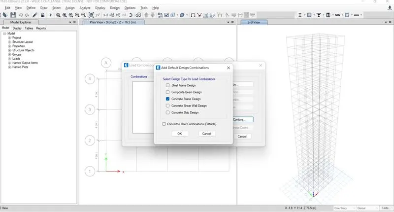
- a new tab will open->click on Add default design combos
- Select concrete frame design
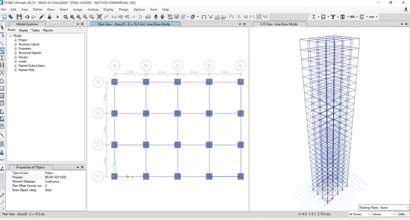
Now Drawing beams and columns:
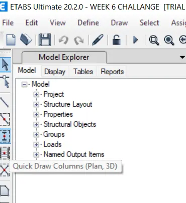
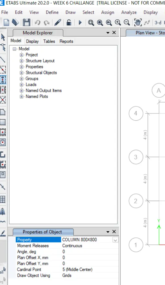
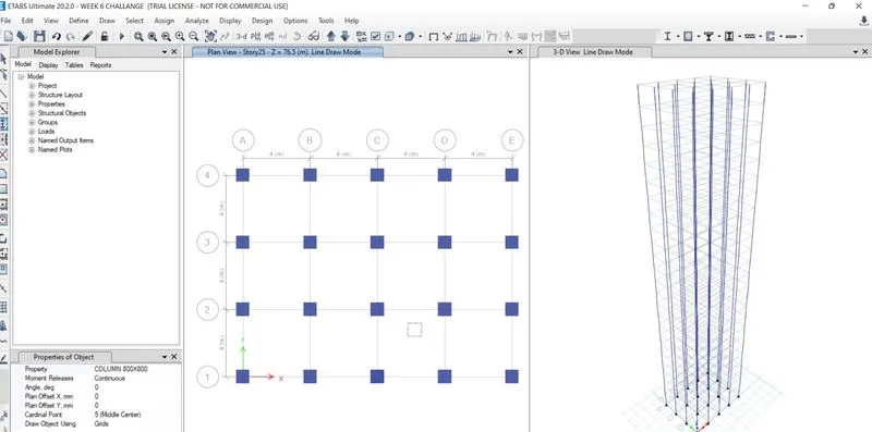
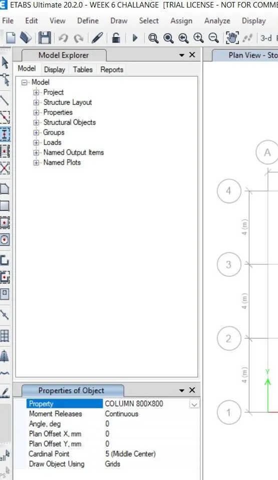
Now beams :
NOW ASSIGNING SLAB PORTIONS :
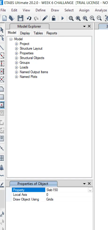
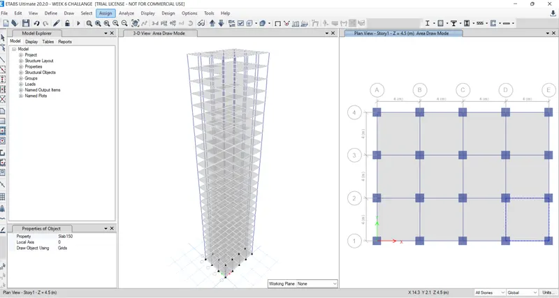
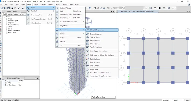
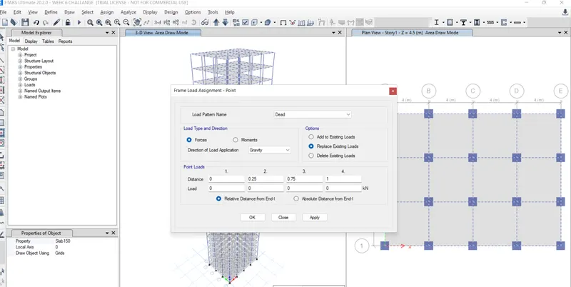
NOW APPLY LVE LOAD -10KN/M.
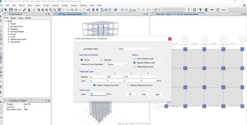
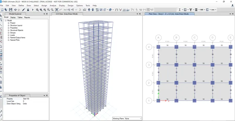
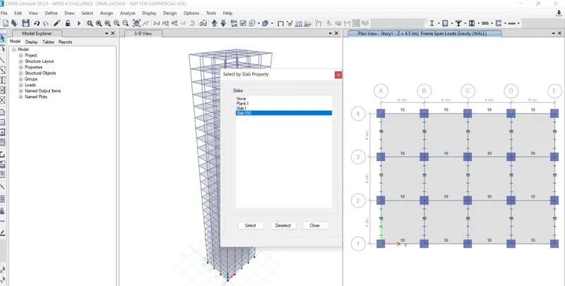
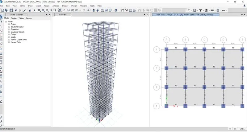
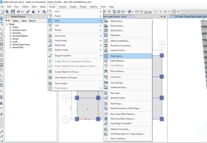
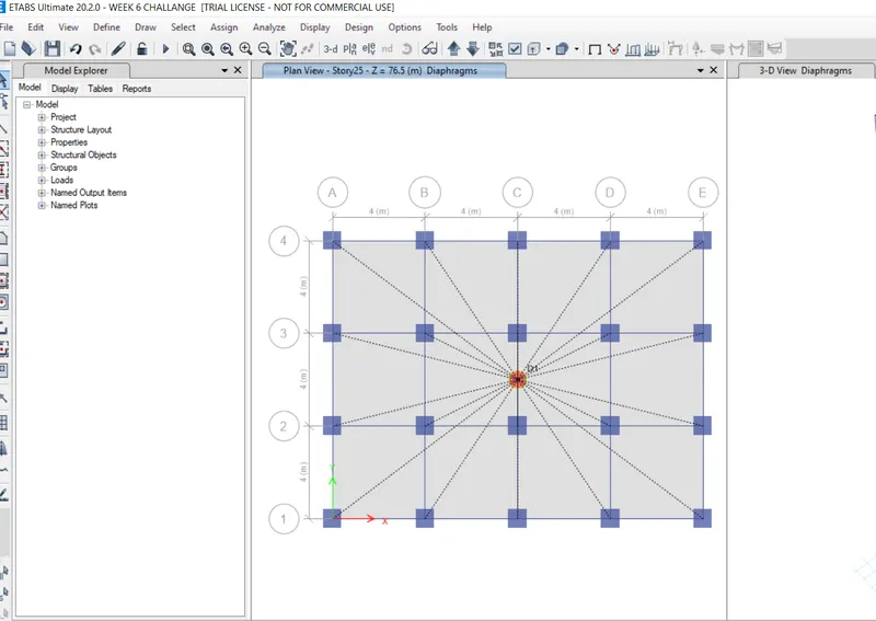
NOW SHELL LOAD PLACEMENT:
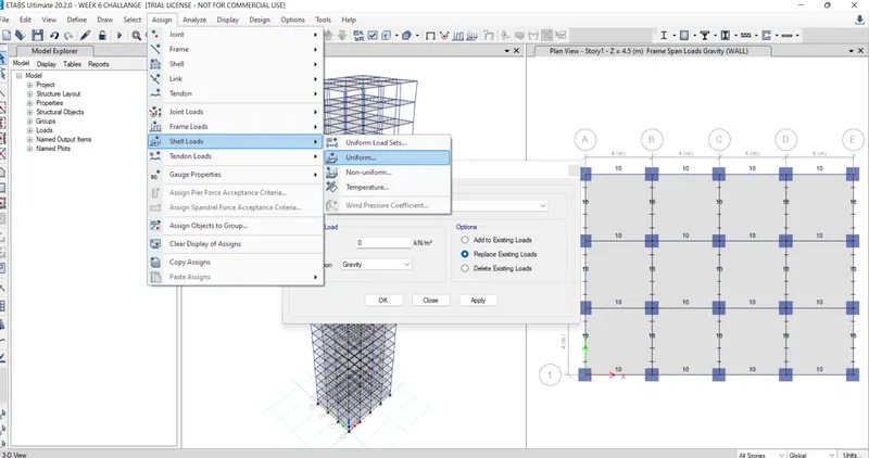
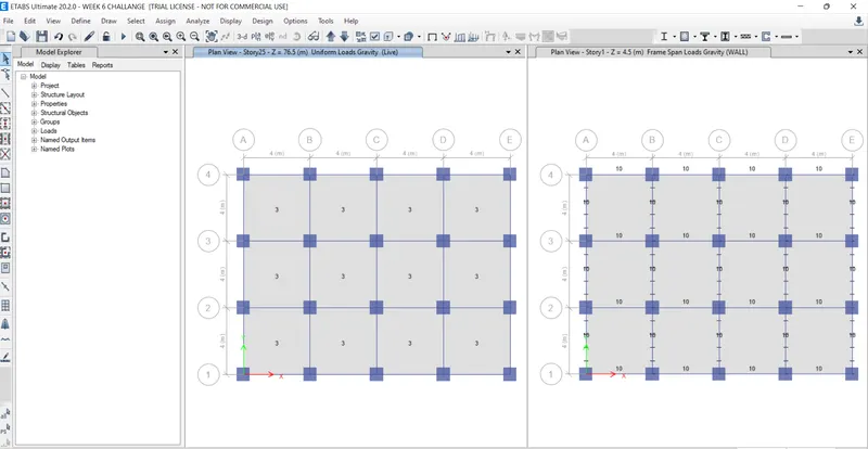
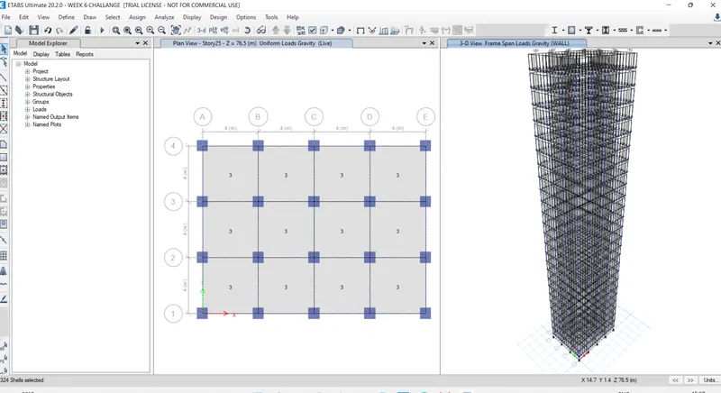
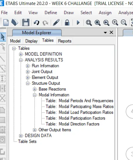
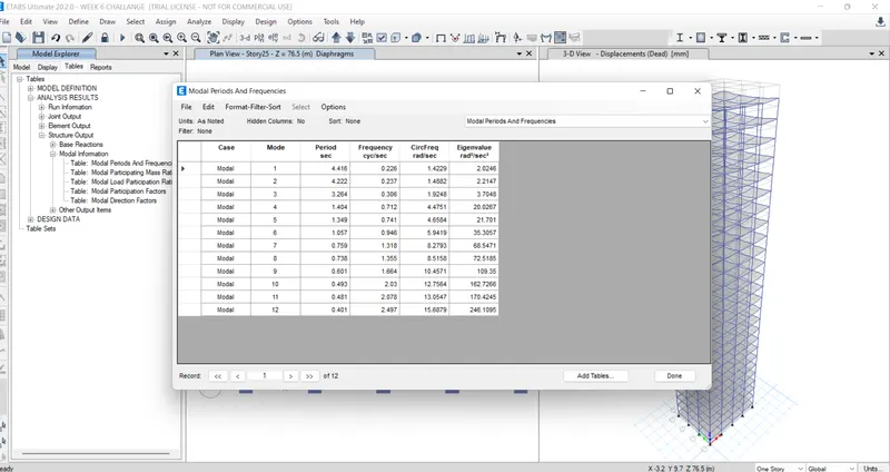
from challange 6:
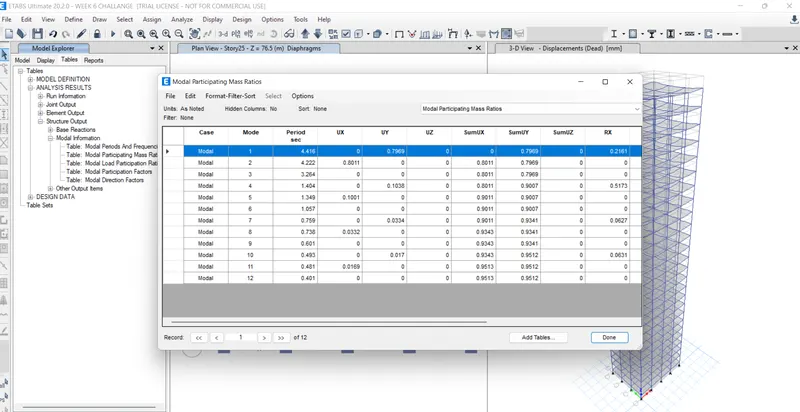
Fundemantal transalation natural period x-direction -as given is -4.4 seconds and exercise result is 4.416.
Fundemantal transalation natural period y-direction -as given is -4.2 seconds and exercise result is 4.22.
Vertical irregularity: acc to IS183-2016 (Part-1) table 6 clause 7:
First three modes togethar should contribute atleast 65% in mass participation factor in each principal direction -YES.
Fundematal natural periods n two principal plane direction area away from each other by atleast 10%. -NO.
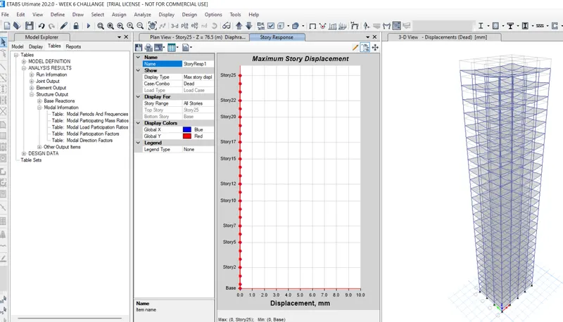
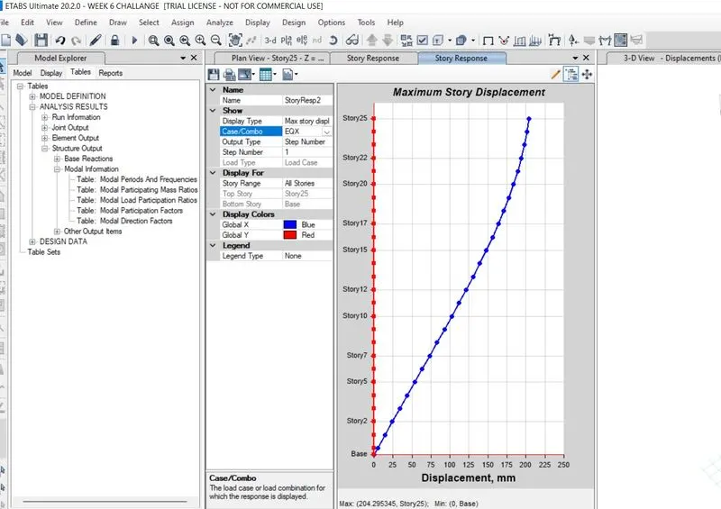
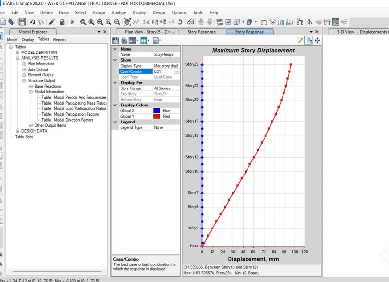
Inter storey -drift : IS 1893-2016 part-1 clause 7.11.1.1 : storey drift shall not exceed 0.004 times the storey height for base shear with no shear load factor(4x10^3) -yes.