Modelling of 25 storey building with the specified properties using ETABS
Challenge 6)
Aim: Model a 25 storey building on ETABS with structural properties as specified.
Opening and steup a new file:
- Open the ETABS software, in the file menu there is an option for new model click on it.
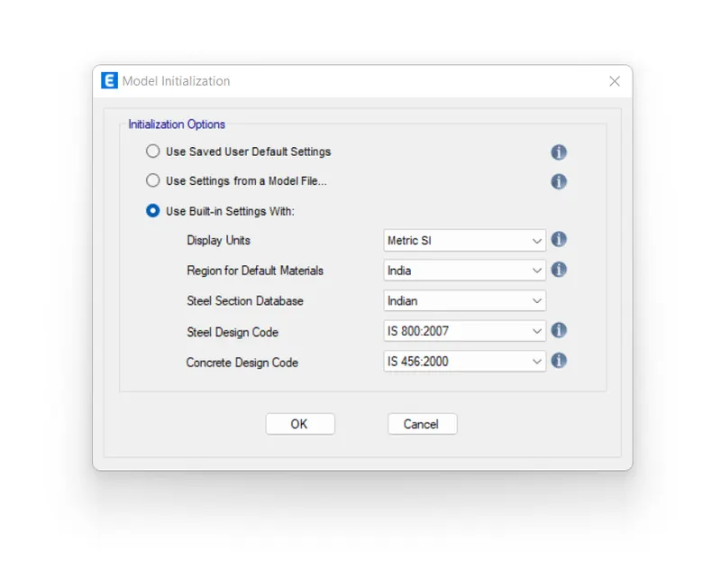
- A new window is display on the screen named 'Model Initializaton', click on the third option 'use built in display with' and select all the required perimeters.
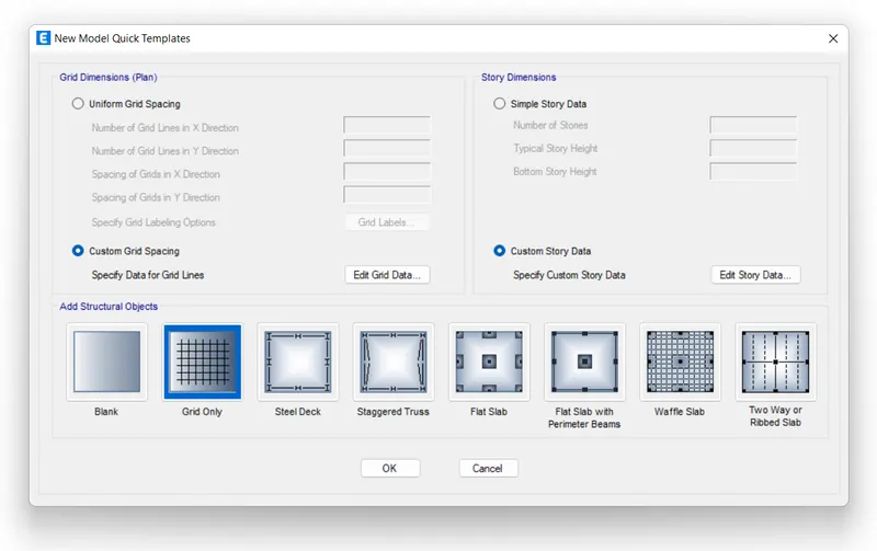
- When click on ok another display appears on screen named 'New Model Quick Template'.
- Give all the grid Dimension and Story Dimensions and press ok.
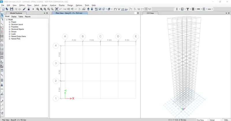
- After entering all the Grid spacing and story data, as per given details the home page of the etabs is visible as shown below.
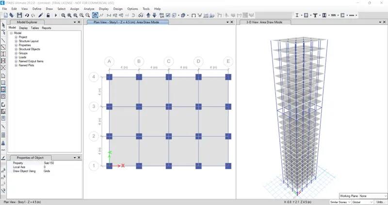
- There are automatically two views generated one is plan view and another one is the 3d view of the drawing.
Defining Materials:
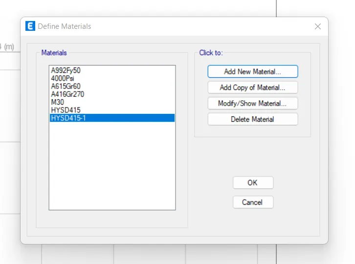
- Now to define material properties, Go to the define tab and click on the Material properties option.
- A new display appears on the screen.
- Click on the add new material option.
- Now select the material type as Concrete and grade as M30.
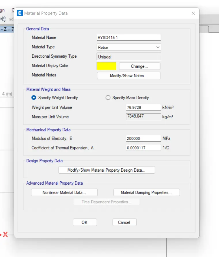
- Click on Ok. Another window displays showing material Property Data, click ok again.
- Again select other material type as Rebar and grade as HYSD 415.
Defining Section Properties:
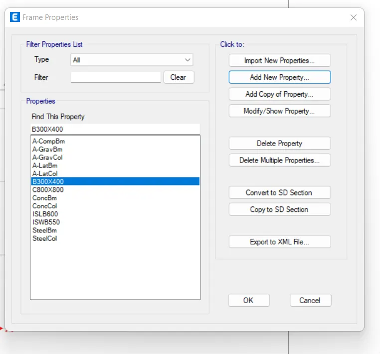
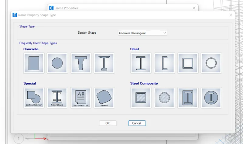
- Now to define section properties, Go to the define tab and click on the Section properties option and then click on frame sections.
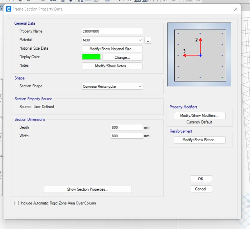
- A new window appears on the screen named Frame Section Property Data.
- Name the property as C800X800 for column.
- Select material as M30 and Give the dimension for depth and widht as 800.
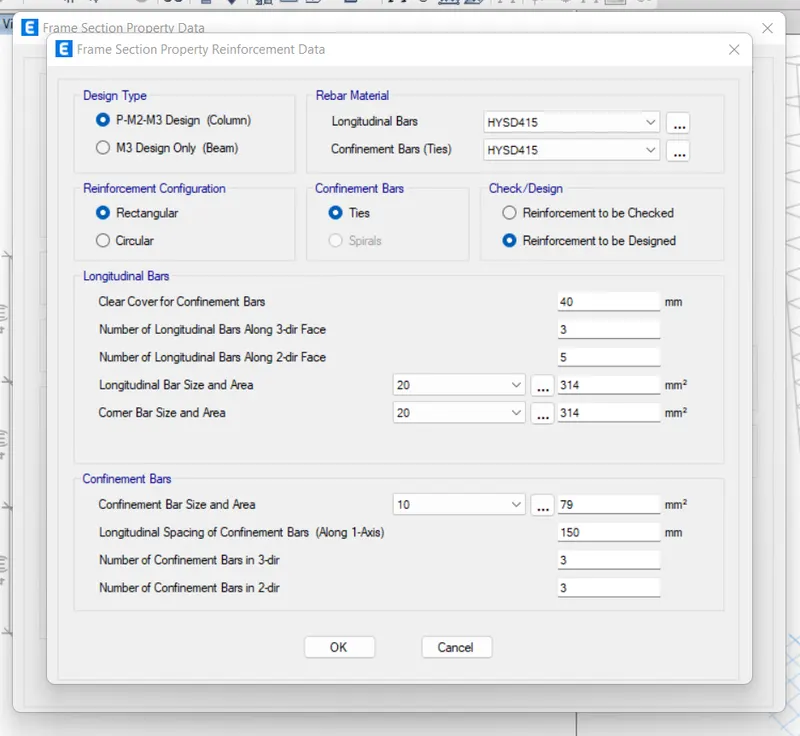
- To provide reinforcement, Click on modify/show Rebar.
- A new tab appears named Frame Section Property Reeinforcement Data.
- Similiarly for the beam follow the same steps as for the column.
- Name the beam as B300X400 and give the depth as 400 and width as 300.
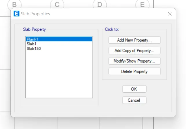
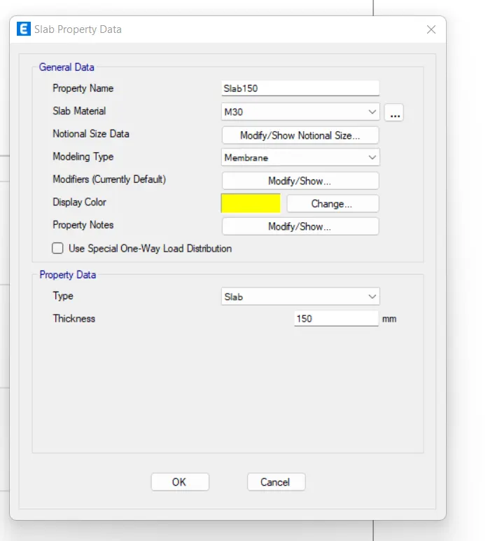
- Similiarly go for the slab sections, Go to define tab click on the section properties and then click on slab section.
- A tab is opened named slab properties, click on add new property option.
- A new tab is opened named slab properties data.
- Enter the Property name as Slab150, Slab material as M30 and modelling type as Membrane.
- In the property data section, select the type as slab and thickness as 150 mm. Click oK.
Defining Load Patterns:
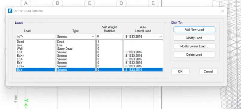
- Now to define load pattern, Go to the define tab and click on the Load pattern option.
- A tab is displayed on the screen, where dead and live load are already present.
- Add another load as wall and enter type as Super dead and click on Add New Load.
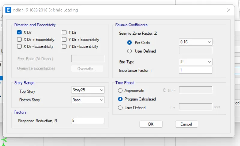
- Similiarly add earthquake load in x and y direction and also add the positve and negative eccentricity of both the x and y.
- And add the Auto Lateral Load as IS 1893:2016. And click Ok.
Defining Mass Source:
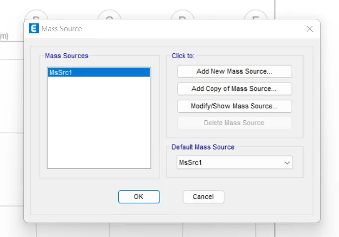
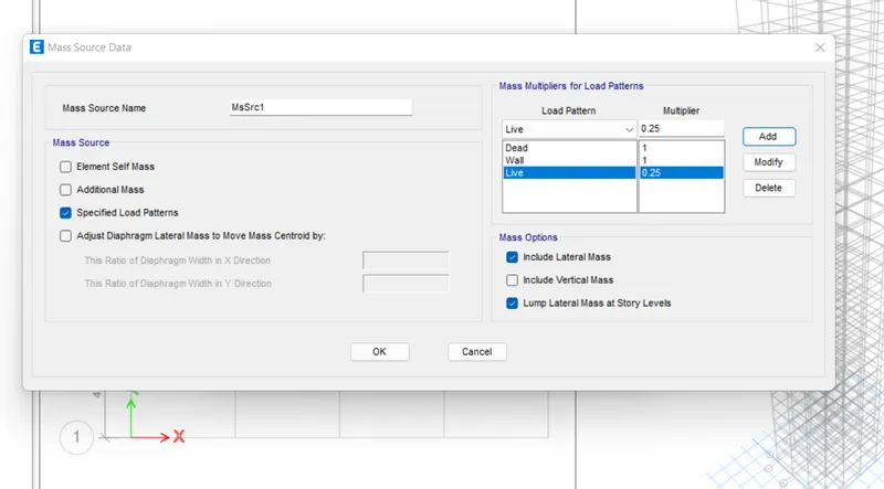
- Now to define Mass Source, Go to the define tab and click on the Mass Source option.
- A new popup displays on the screen click on modify/show mass source.
- A new diplay appears on the screen, named mass source data.
- Add the mass multipliers for load patterns 100% for dead and wall load and 25% for live load.
- Click on oK twice.
Defining Load Combination:
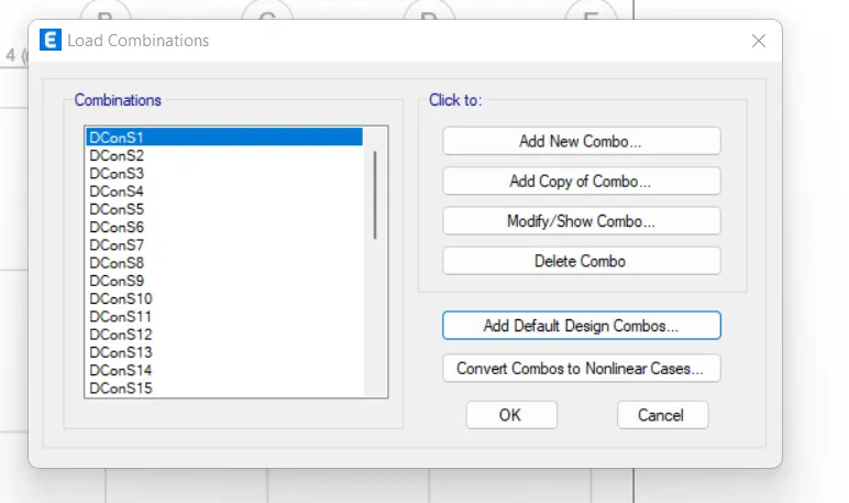
- Now to define load combination, Go to the define tab and click on the Load combination option.
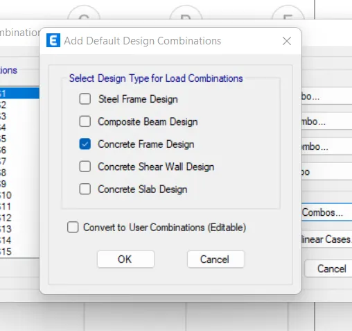
- Click on Add Default and Design combos.
- Select the concrete frame design option, and click oK twice.
Modelling of columns:
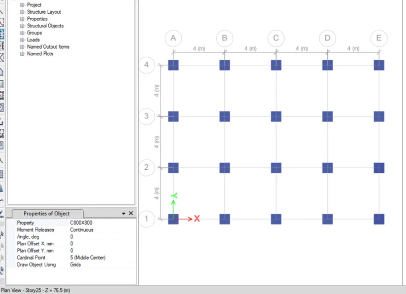
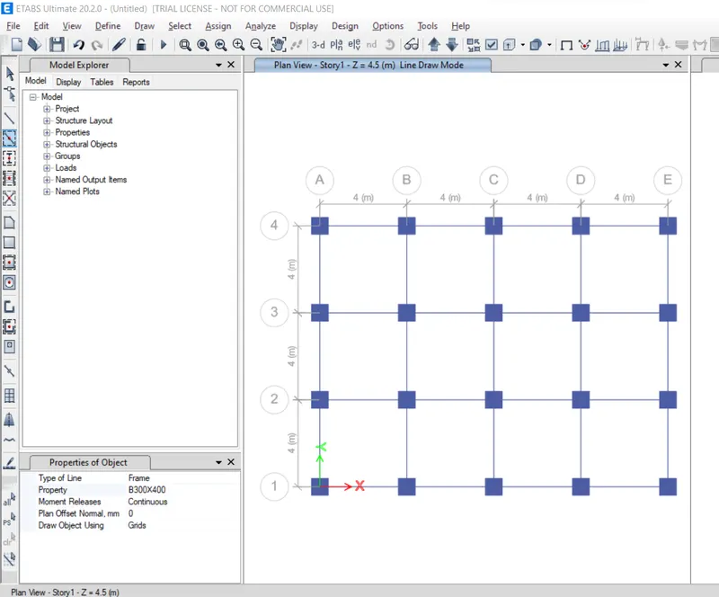
- Go for quick draw columns option, In the properties of object select the C800X800.
- Select the all stories option as the column is created on all the stories of the building.
- Click on each of the grid to create the column of the grids.
Modelling of beams:
- Go for quick draw beams option, In the properties of object select the B300X400.
- Select the all stories option as the beam is created on all the stories of the building.
- Click on each of the grid to create the beams between the grids.
Modelling of slabs:
- Go for quick draw floors option, In the properties of object select the S150.
- Select the Similiar stories option as the slab is not created on base and plinth of the building.
- Click on each of the grid to create the slabs between the grids.
- Now select all the beams, Go to the select tab then click on select the object and select the object type as beam.
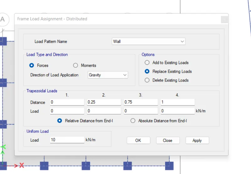
- Go to the Assign tab, select the frame loads and click on the distributed opton.
- A tab is opened named as the frame load assignment- Distributed.
- Select the Load pattern name as Wall and give the load as 10kn/m. Click on apply and then click on close.
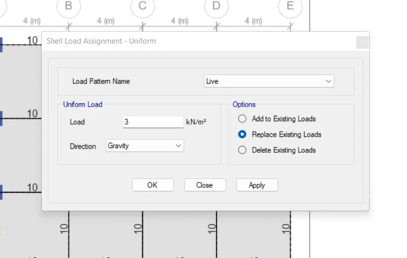
- Similiarly select all the slabs, and apply the loads.
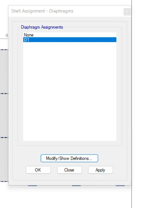
- And again select the slab for diaphragms.
- Go to assign tab, then go to the shell option and click on the diaphgram option.
- A new tab is displayed on the screen ,Click on D1 then click on apply and press ok.
- Now click on the Run Analysis or the shortcut key for the run analysis is F5.
Exercise:
- Fundamental Translational Natural Period:
- X-direction 4.385 that is similiar to 4.4
- Y-direction 4.193 which is similiar to 4.2
- Yes, Torsional mode time period is lesser than X and Y direction time period.
- Yes, the first threee mode together contributes more than 65% in mass participation.
- No, Fundamental lateral period in two principal plane direction are away from each other by 10%.
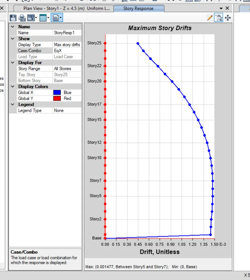
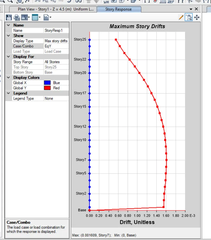
- Yes, the storey drift not exceed 0.004 times the story height.