Modelling, Assemble and apply GD&T to the butterfly valve
Objective: To design and assemble all the components of a Butterfly Valve in a 3D modeling software, and then apply Geometric Dimensioning and Tolerancing (GD&T) symbols to the final drawing sheet.
Introduction to Butterfly valve:
- A butterfly valve is a type of quarter-turn valve used to regulate or isolate the flow of fluid through a pipe. The valve is named after its disc, which is usually shaped like a butterfly and is connected to a rod that passes through the center of the disc. The disc is rotated a quarter turn to open or close the valve.
- Butterfly valves are commonly used in applications where a tight shut-off is not required. They are simple, lightweight, and easy to install, making them a popular choice for a variety of industrial and commercial applications.
Introduction to Geometric Dimensioning & Tolerancing:
- Geometric Dimensioning and Tolerancing (GD&T) is a system used to define and communicate the tolerances and geometric requirements of a product or part. It is a symbolic language that uses standard symbols, rules, and definitions to specify the size, shape, orientation, and location of features on a part.
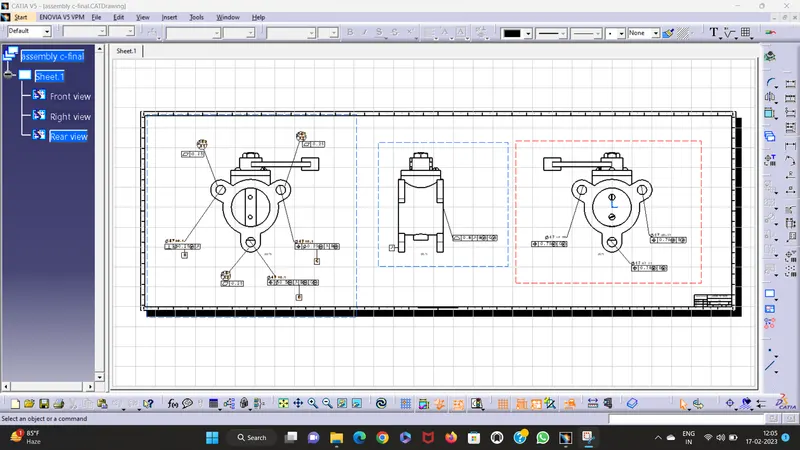
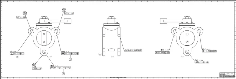
- Here after modelling various components of the Butterfly valve, GD&T (Geometric Dimensioning & Tolerancing) is applied to each component and final assembly.Geometric Dimensioning and Tolerancing (GD&T) is a system for defining and communicating engineering tolerances.
- Next, the designer would use feature control frames and other GD&T symbols to specify the allowable variation in these critical features. For example, the diameter of the disc may be defined using a basic dimension, and a tolerance could be specified using a geometric tolerance symbol such as a diameter symbol with a tolerance value.
Advantages of GD&T:
-
Improved communication: GD&T provides a precise and standardized way to communicate design requirements between designers, engineers, and manufacturers. This helps to reduce errors and misunderstandings and ensures that all parties have a clear understanding of the required dimensions and tolerances.
-
Increased accuracy: GD&T allows for more precise control of part geometry and location. This can lead to improved accuracy and performance of the finished product, as well as reduced scrap and rework.
-
Cost savings: By specifying the allowable variation in part dimensions and tolerances, GD&T can help to reduce the amount of material needed and the number of manufacturing steps required. This can result in cost savings for the manufacturer and the end customer.
Application of GD&T:
-
Automotive: GD&T is used extensively in the automotive industry to ensure the quality and precision of components such as engines, transmissions, and suspension systems.
-
Medical devices: GD&T is used to ensure the accuracy and safety of medical devices such as pacemakers, artificial joints, and surgical instruments.
-
Consumer products: GD&T is used in the design and manufacturing of a wide range of consumer products, from small electronic devices to complex machinery.
-
Industrial machinery: GD&T is used to ensure the accuracy and performance of industrial machinery such as turbines, pumps, and compressors.
-
Tool and die manufacturing: GD&T is used to ensure the accuracy and precision of the tooling and dies used in manufacturing processes such as stamping, molding, and casting.
Overall, GD&T is a versatile tool that can be applied to a wide range of manufacturing processes and industries to ensure the accuracy, reliability, and safety of mechanical components.
Some of the key reasons for using GD&T include:
- Provides a precise and consistent method for communicating design intent.
- Simplifies tolerance analysis.
- Facilitates and simplifies gaging requirements.
- Reduces the need to explain complex requirements.
- Identifies critical-to-function features.
COMPONENTS OF BUTTERFLY VALVE
Various components of butterfly valve and GD&T applied to them are shown below.
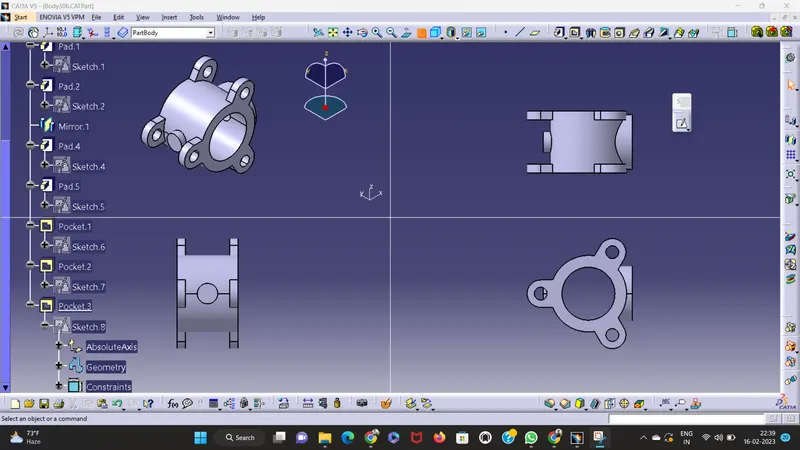
1. BODY - BUTTERFLY VALVE:
To model a butterfly valve body in CATIA V5, you can follow these steps:
-
Open a new CATIA V5 part document.
-
Create a sketch on the XY plane and draw the outline of the butterfly valve body. The sketch should include the disc, the stem, and any mounting holes or flanges. Use dimensions and constraints to define the geometry of the sketch.
-
Use the Extrude command to create a solid body from the sketch. Specify the thickness of the body and choose the direction of the extrusion.
-
Use the Pocket command to remove material from the butterfly valve body, leaving the disc shape. Specify the depth of the pocket and choose the direction of the cut.
-
Create a sketch on the top face of the butterfly valve body and draw the outline of the disc. Use dimensions and constraints to define the size and location of the disc.
-
Use the Fillet command to add fillets to the edges of the butterfly valve body and any other features. Specify the radius of the fillets.
2. SHAFT - BUTTERFLY VALVE:
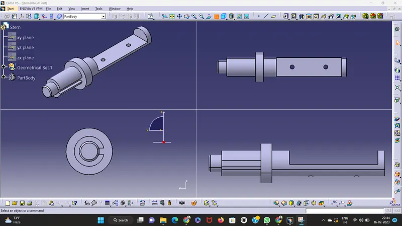
- Follow first three steps in above body procedure.
-
Create a sketch on one end face of the shaft and draw the outline of the stem that will fit into the butterfly valve body.
-
Use dimensions and constraints to define the size and location of the stem.
-
Use the Hole command to create a hole through the end of the shaft for the stem.
-
Specify the diameter and depth of the hole, and choose the location and orientation of the hole.
-
Create any additional sketches and features as needed, such as grooves or keyways for connecting to the butterfly valve disc.
The disc/plate, lever and nut are assembled to this shaft.
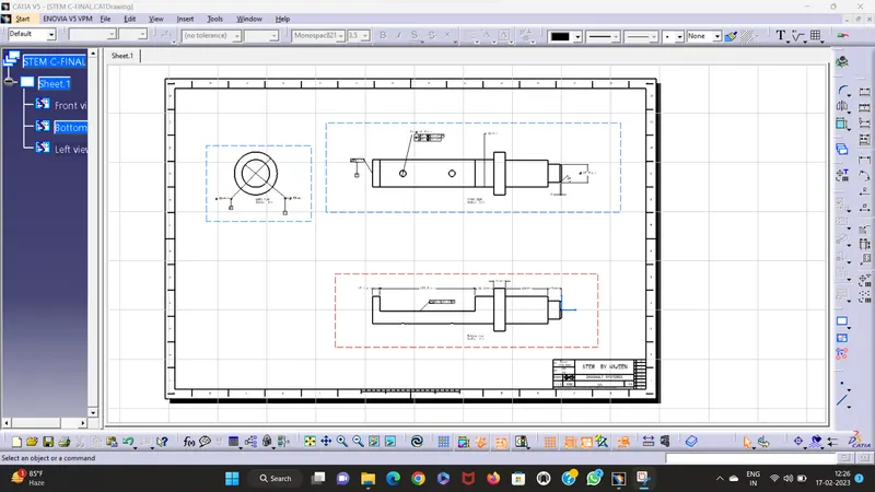
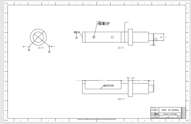
Drafting:
-
Open the CATIA V5 part document containing the butterfly valve shaft model.
-
Click on the Drafting workbench to open a new drawing document.
-
In the new drawing document, select the orientation of the drawing sheet, the sheet size, and the scale.
-
Click on the “Insert a View” icon and select the butterfly valve shaft model to insert it into the drawing.
-
Use the “Drawing Views” toolbar to add any necessary annotations such as dimensions, tolerances, and notes.
-
Use the “Text” toolbar to add any additional text annotations, such as the title of the drawing, the name of the part, and the name of the manufacturer.
-
Add a Bill of Materials (BOM) to the drawing by clicking on the “Insert a BOM” icon and selecting the appropriate properties to include in the BOM.
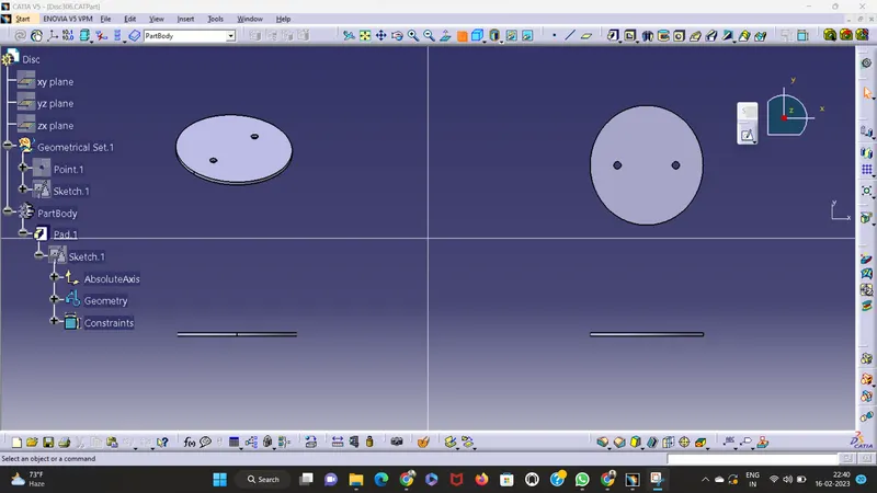
3. DISC - BUTTERFLY VALVE:
- When valve is fully opened or closed the disc is rotated a quarter turn.
- Disc is mounted on shaft.
- The disc is rotated a quarter turn so that it allows an almost unrestricted passage of the fluid.
Follow the above procedure to design the disc.
-
Use the Extrude command to create a solid body from the sketch. Specify the thickness of the disc and choose the direction of the extrusion.
-
Create any additional sketches and features as needed, such as mounting holes or keyways.
-
Use the Fillet command to add fillets to the edges of the disc and any other features. Specify the radius of the fillets.
Drafting:
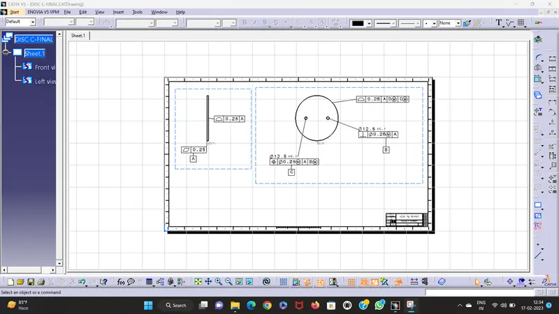
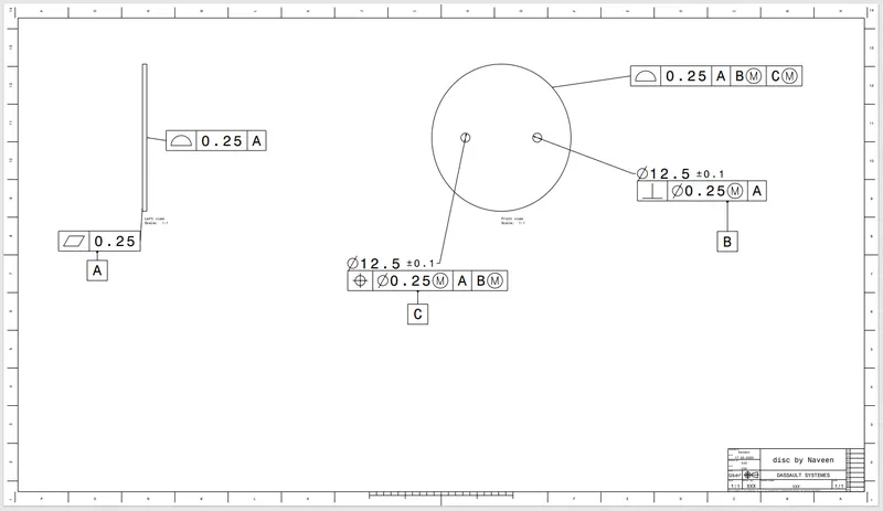
-
In the new drawing document, select the orientation of the drawing sheet, the sheet size, and the scale.
-
Click on the “Insert a View” icon and select the butterfly valve disc model to insert it into the drawing.
-
Use the “Drawing Views” toolbar to add any necessary annotations such as dimensions, tolerances, and notes.
-
Use the “Text” toolbar to add any additional text annotations, such as the title of the drawing, the name of the part, and the name of the manufacturer.
-
Add a Bill of Materials (BOM) to the drawing by clicking on the “Insert a BOM” icon and selecting the appropriate properties to include in the BOM.
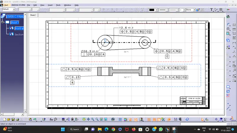
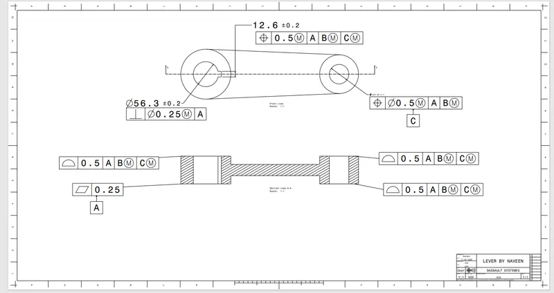
4. LEVER - BUTTERFLY VALVE:
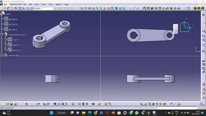
- Lever is mounted at an end of shaft outside the body.
- Hand lever is usually used in small sized Butterfly valves.
- It is used to open or close the valve.
Follow the above procedure to model the lever.
5. RETAINER - BUTTERFLY VALVE:
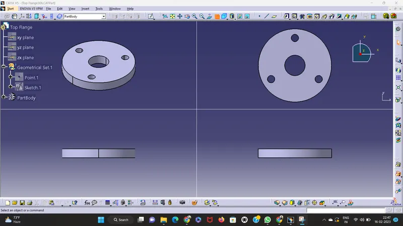
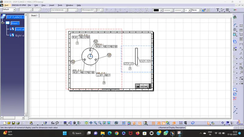
- Retainer is a kind of washer fixed on the body of butterfly valve.
- Follow the above procedure to design and 2D drafting of Retainer.
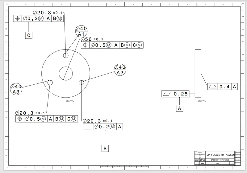
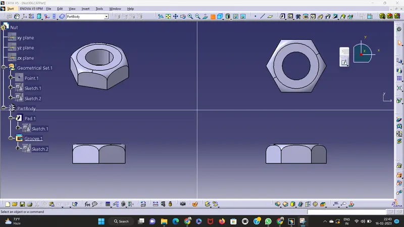
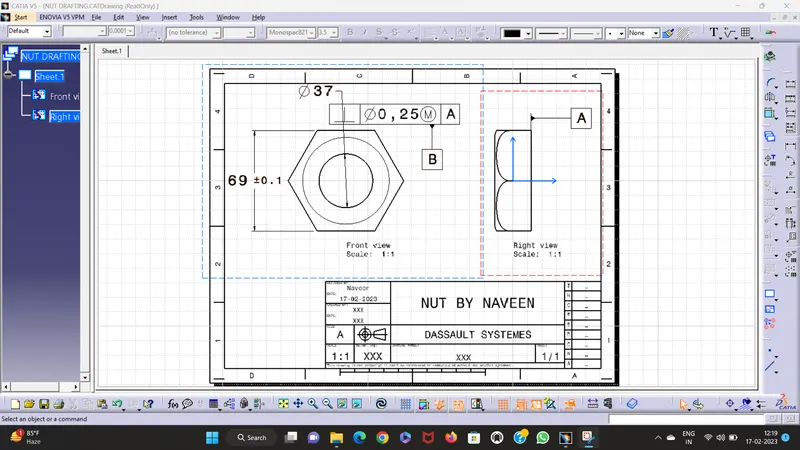
6. NUT - BUTTERFLY VALVE:
Follow the above procedure to design and 2D drafting of nut.
It is fixed at the top end of shaft to keep the lever and retainer on position relative to the body of butterfly valve.
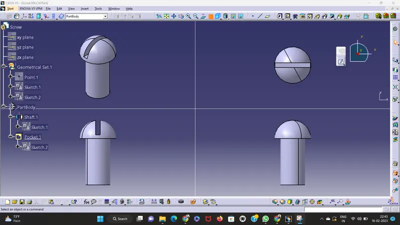
Additional component: Screw
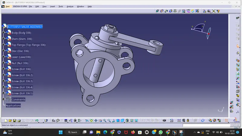
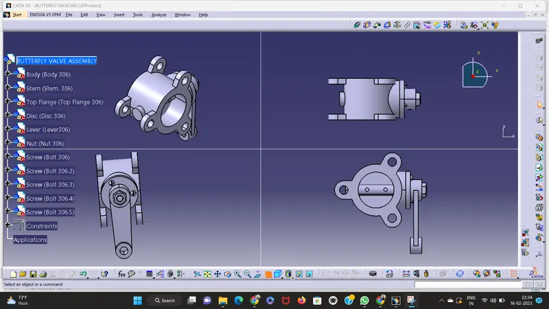
ASSEMBLY - BUTTERFLY VALVE:
- Open a new CATIA V5 assembly document.
- Use the “Insert a Component” icon to insert the butterfly valve body, shaft, and disc models into the assembly.
- Fix the body by using Fix comand.
- To assemble the components use the Manipulation, contact, coincidence constraint.
- Use the “Constraints” toolbar to add constraints between the components, such as coincident, parallel, and concentric constraints. For example, constrain the shaft to the center of the disc, and the disc to the inside of the butterfly valve body.
CONCLUSION:
Butterfly valve assembly was successfully designed and applied GD&T to all parts and the assembly as shown above report.