Base Bracket
Objective:To Create the Base Bracket Plastic component through the given Class-A surface. To begin with, the tooling axis for the given Class-A Surface should be created meeting the requirements of the draft angle and at the end perform the Draft analysis on the model.
TOOLING AXIS :
- First Check for clearence in all the axis directions will Completed by creating an intersection through an axis on a plane with the model and the constructing two lines contact with the walls on it, the line intersecting the two lines and passing through the point on the tooling axis.drafting analysis is done by the reference of tooling axis.
CLASIFICATION OF SURFACES:
The clasification of surfaces are Class A, Class B, ClassC.
Class A:
- Class A surface is a visible exterior surface of a product. for example take an automobile, that should be present in high-quality appearance. To create Class A surfaces , engineers use features within their design software. that show the connections between the different panels to make up the surface.
Class B:
- Class B surface is always not visible surface to the Customer (the underside of a product that would have to bend down to see it).
Class C:
- Class C surface is the back side surface of a part that is permanently covered by another part. Class C is present in between Class A and Class B surfaces.
Steps to Create Class A,B,C surfaces to the given Base Bracket:
STEP 1: TOOLING AXIS:
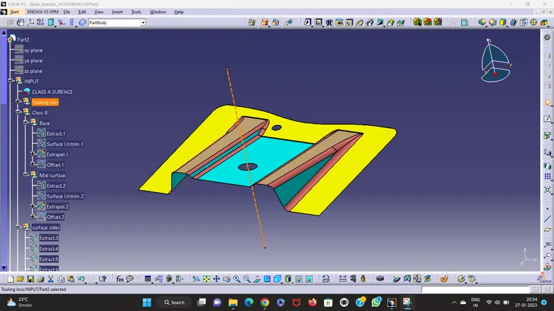
- Create a tooling axis on a given model (base bracket) by selecting convienient to the drafting analysis'
- click on point and select the circle surface one dialoge box wll appear select circle/sphere/elipse and click on ok.
click on line and select point-direction in dialog box and click on point and click on ok.
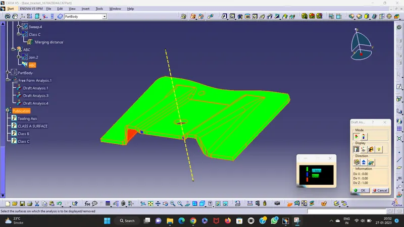
STEP 2: DRAFTING ANALYSIS ON CLASS-A SURFACE:
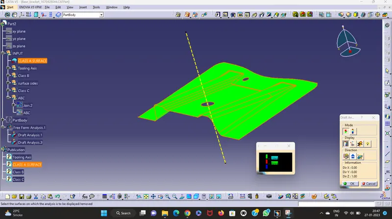
- click on insert---analysis---FEATURE DRAFT ANALYSIS
- Drag the compass to the tooling axis
- click on compass in the dialog box---drag some distance---lock it---select the surface with respect to the tooling axis.
- If the entire surface is appear in green in clour the drafting analysis is correct if not make corrections according to it.
STEP 3: CREATION OF CLASS-B SURFACE:
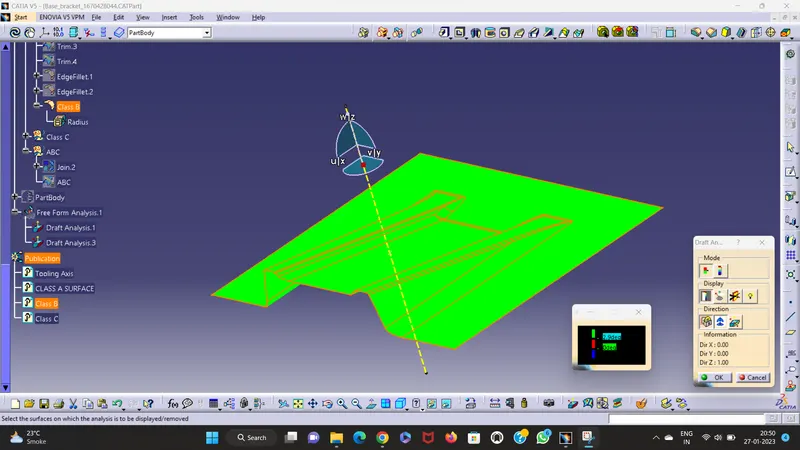
- click on extract command click on surface and click on ok.
- click on untrim command and click on surface and click on ok.
- click on extrapolate command and click on surface and click on ok.
- click on off-set command and click on surface give a value of 2.5mm and click on ok.
- click on trim command to trim the exta surface acording to the need.
- click on edge fillet command and give the fillet value of 3mm and 1 mm at the edges.
STEP 4: CREATION OF CLASS-C SURFACE:
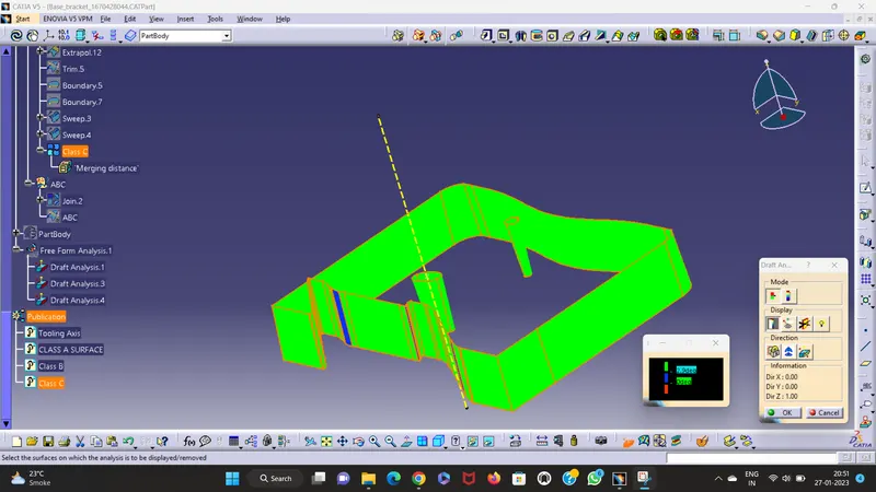
- click on boundary command and click in edge of the surface and give the limit and click on ok.
- click on draft command to the give the draft angle and give the value.
- click on extrapolate command and click on surface and click on ok.
- click on trim command to trim the exta surface acording to the need.
STEP 5: CREATION OF CLASS-A,B,C SURFACE:
- Click on join command to join all the surfaces to make it as complete surface model.
STEP 6: CREATION OF SOLID:
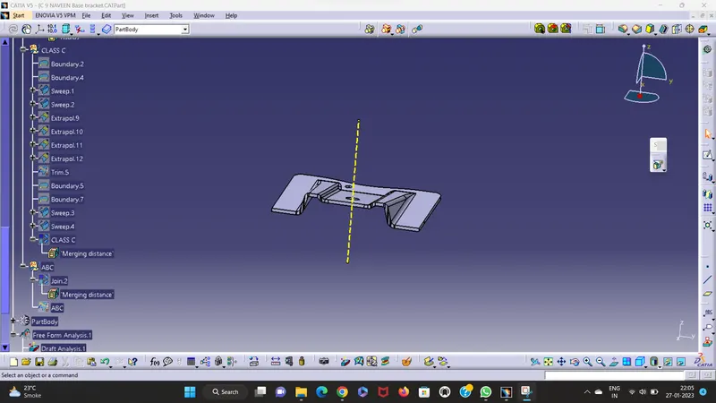
- Click on start, click on mechanical design and select part design.
- click on part body and click on define part body and click on fill surface and click on ok.
STEP 7: DRAFT ANALYSIS SOLID MODEL:
- click on insert and click on analysis and click on FEATURE DRAFT ANALYSIS
- Drag the compass to the tooling axis.
- click on compass in the dialog box and drag some distance and click on lock it and then select the surface with respect to the tooling axis.
- If the entire surface is appear in green in clour the drafting analysis is correct if not make corrections according to it.
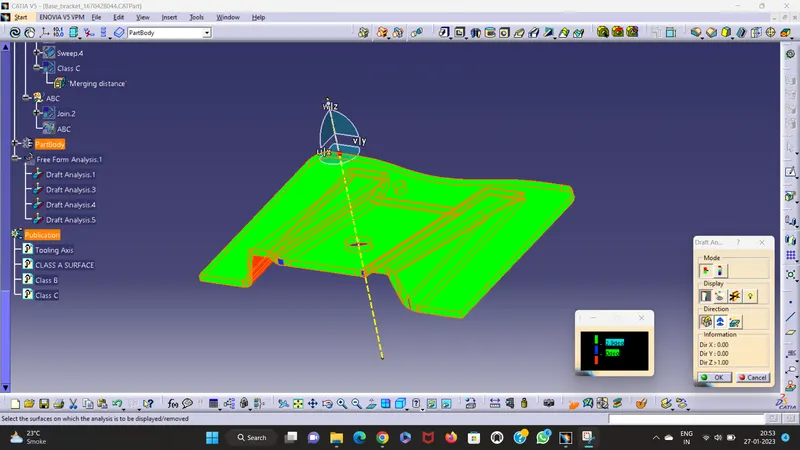
Conclusion: Hence the solid body of the Base Bracket was made successfully with Draft Analysis.