Development of a Door Trim panel
Objective:
The objective of this project is to manufacture a solid body for a side door trim of a vehicle, using the four given parts which are the Lower Substrate, Bottle Holder, Map Pocket, and Door Armrest. Additionally, B side features such as the doghouse, heat stake, and locator must be incorporated while adhering to the relevant design rules and guidelines.
Theory:
Role of plastics in the Automotive industry:
Plastics play a significant role in the automotive industry, as they are lightweight, durable, and can be easily molded into various shapes and sizes. Here are some specific roles of plastics in the automotive industry:
-
Lightweighting: Plastics are much lighter than traditional materials like metal, which helps reduce the overall weight of the vehicle. This can lead to improved fuel efficiency and reduced emissions.
-
Safety: Plastics can be engineered to absorb energy during a crash, which can help protect passengers and reduce injuries.
-
Design and aesthetics: Plastics can be molded into complex shapes and designs, allowing automotive manufacturers to create unique and attractive designs for their vehicles.
-
Durability: Plastics are highly resistant to corrosion, chemicals, and weathering, which makes them ideal for use in harsh automotive environments.
-
Noise and vibration reduction: Plastics can be used to dampen noise and vibration in a vehicle, which can improve the overall driving experience for passengers.
-
Cost-effectiveness: Plastics can be produced at a lower cost than traditional materials, which can help reduce the overall cost of a vehicle.
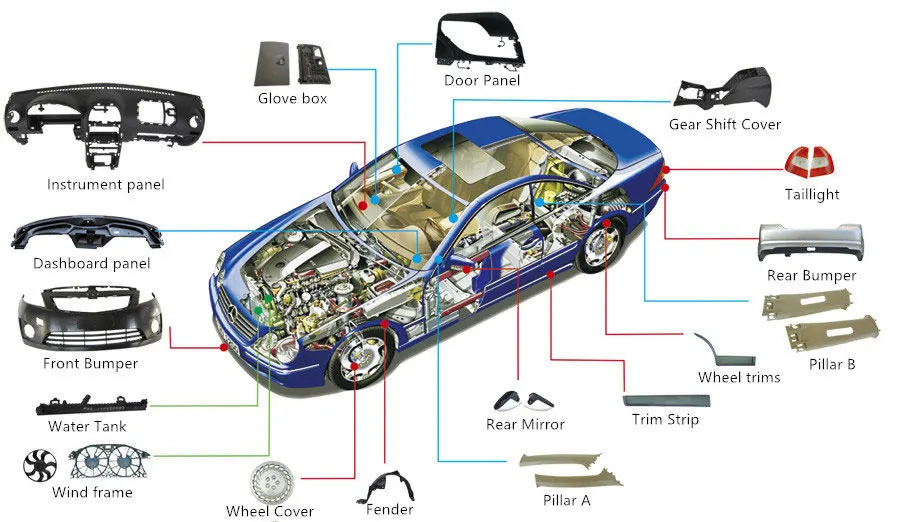
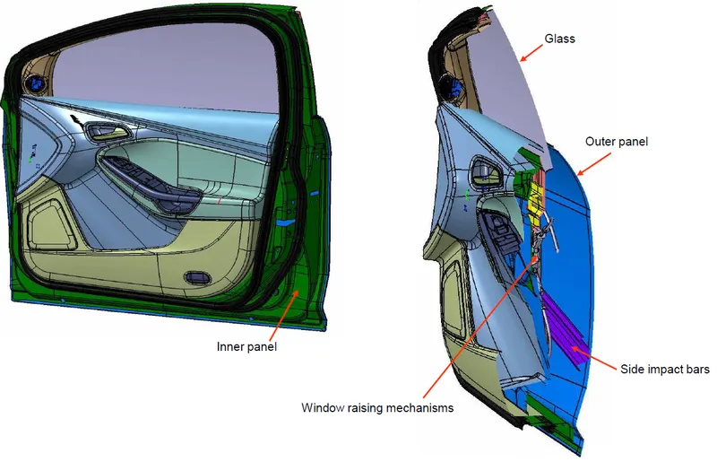
Plastic parts are all individually designed and manufactured by a method called injection moulding and then later using attachment features they are all assembled together to make it a functionable component.
Manufacturing Process:
Injection Moulding:
- Injection molding is a manufacturing process used to produce a wide range of plastic products by injecting molten plastic material into a mold cavity. The process involves melting plastic pellets or granules and injecting them into a mold under high pressure. The plastic then cools and solidifies inside the mold, taking the shape of the mold cavity.
- The process is commonly used for producing high-volume, mass-produced plastic parts, such as automotive parts, electronic housings, containers, toys, and many other consumer and industrial products. It offers several advantages over other manufacturing methods, including high production rates, low labor costs, and the ability to produce complex parts with high accuracy and repeatability.
The steps involved in injection molding are:
-
Clamping: The two halves of the mold are securely closed together using a clamping unit to prevent any plastic from leaking out.
-
Injection: The plastic material is melted and injected into the mold cavity under high pressure using an injection unit.
-
Dwelling: The plastic material is allowed to dwell or remain in the mold for a specific amount of time to ensure it fully fills the mold cavity.
-
Cooling: The plastic material is cooled and solidified inside the mold using a cooling system, typically by circulating water or other coolant through the mold.
-
Mold opening: The clamping unit is opened, and the two halves of the mold are separated, allowing the finished part to be ejected.
-
Ejection: The finished part is ejected from the mold using an ejection system, such as pins or ejector plates.
-
Recycling: Any excess plastic material is usually recycled and reused in future injection molding runs to minimize waste and reduce costs.
Tooling Direction for Plastic Part:
The tooling direction for a plastic part refers to the orientation of the part relative to the direction of the mold opening. The tooling direction is an important consideration in injection molding because it can affect the strength, appearance, and quality of the finished part.
There are two primary tooling directions used in injection molding:
-
Longitudinal Tooling: The part is oriented in the direction of the mold opening, with the longest dimension of the part parallel to the mold opening. Longitudinal tooling is typically used for parts with a uniform thickness and simple geometries.
-
Transverse Tooling: The part is oriented perpendicular to the mold opening, with the longest dimension of the part perpendicular to the mold opening. Transverse tooling is typically used for parts with complex geometries, varying thicknesses, or when a high-quality surface finish is required.
The choice of tooling direction depends on a variety of factors, including the part geometry, the material being used, the desired strength and appearance of the finished part, and the production process. In general, parts with simple geometries and uniform wall thicknesses are more suitable for longitudinal tooling, while parts with complex geometries or varying wall thicknesses are better suited for transverse tooling.
Procedure :
MASTER SECTION
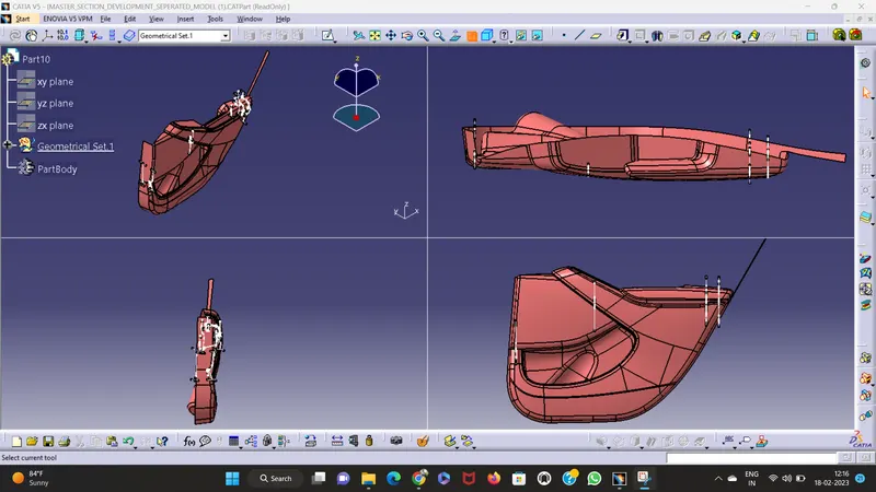
1.Surface classes :
In product design and manufacturing, the surfaces of a part are often classified into three groups, known as A-surface, B-surface, and C-surface.
-
A-surface: The A-surface is the primary visible surface of the part, and it is the surface that will be seen by the end user. This surface is typically the highest quality surface, with a smooth and defect-free finish that is free of visible parting lines or other molding marks.
-
B-surface: The B-surface is the secondary visible surface of the part, and it is typically the opposite side of the part from the A-surface. The B-surface may be visible in certain applications or angles, and it is important to ensure that it is consistent with the overall appearance of the part.
-
C-surface: The C-surface is the non-visible surface of the part, and it is typically the side of the part that is in contact with the mold during the injection molding process.
1.1 A- class surface :
Following points are related to A-Surfaces :
- To design the outer visible surface of part
- Design in this way to maintain aesthetic look of parts .
- A- surface may have texture .
The first step to follow in this project is to extract the CLASS-A surface.
1.Door arm rest
2.Lower substrate
3.Map pocket
4.Bottle holder
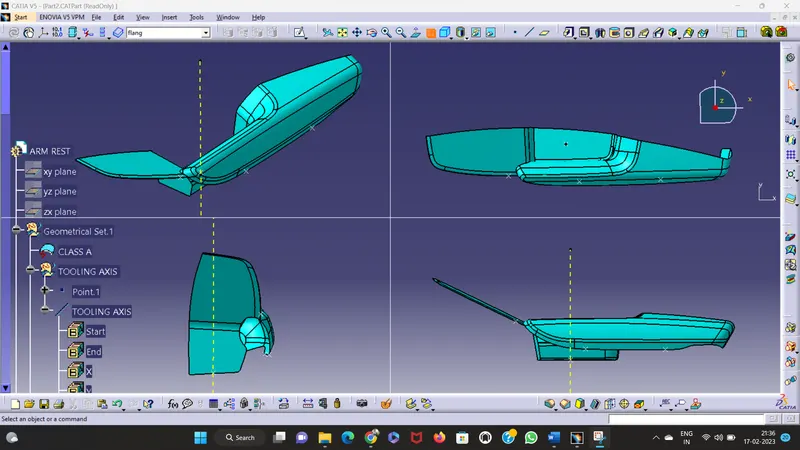
1.1.DOOR ARM REST CLASS A SURFACE :
1.2.LOWER SUBSTRATE CLASS A SURFACE :
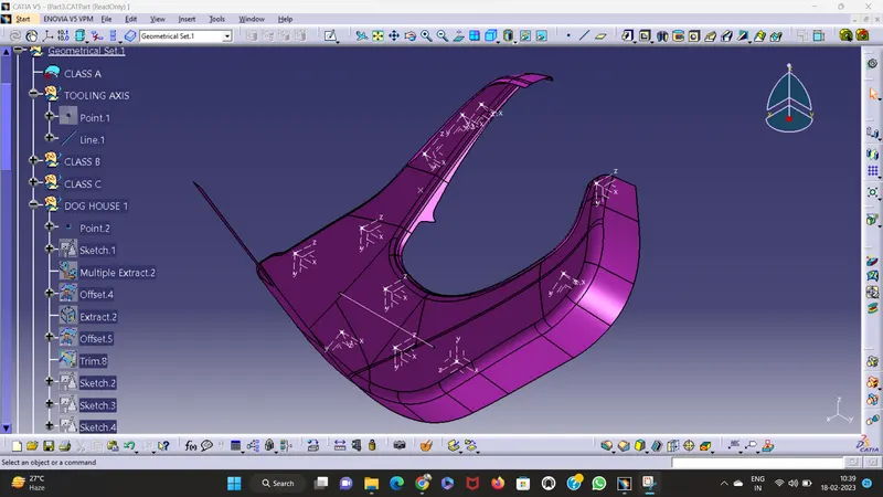
1.3.MAP POCKET CLASS A SURFACE :
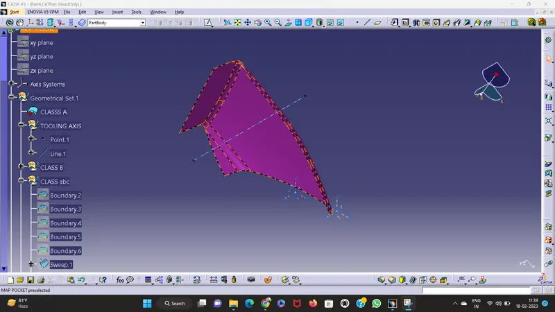
1.4.BOTTLE HOLDER CLASS A SURFACE :
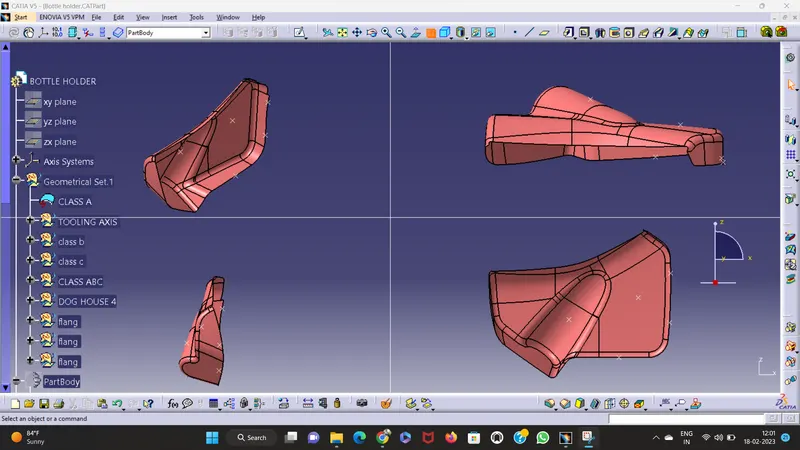
OVERALL CLASSS A SURACES :
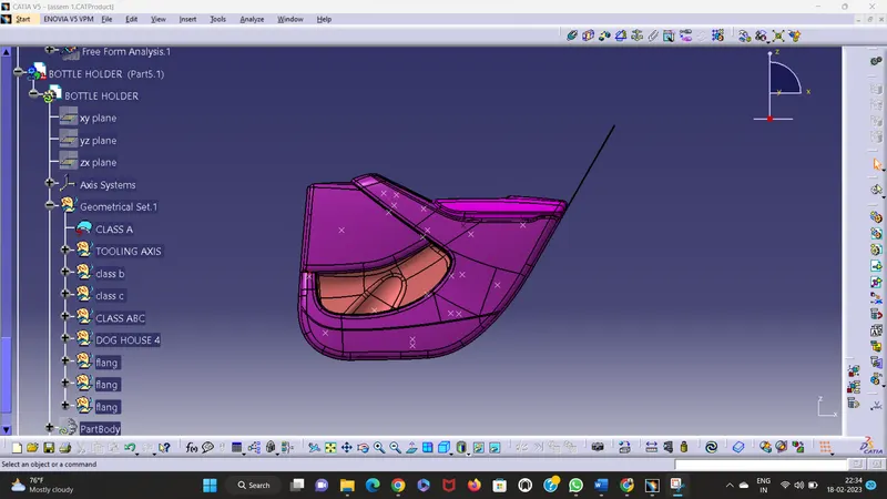
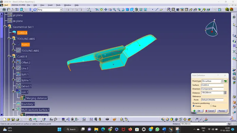
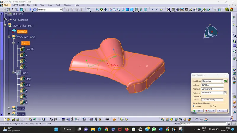
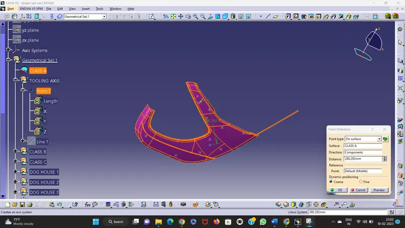
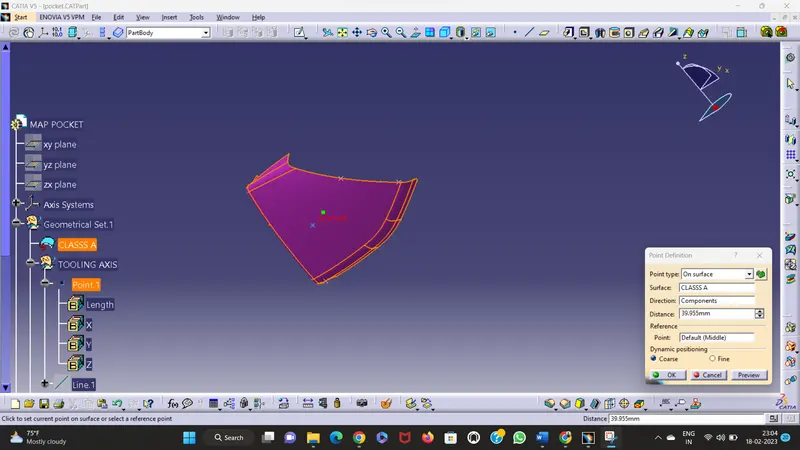
CREATING THE POINT FOR THE ALL THE COMPONENTS (ON THE SURFACE )
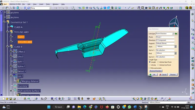
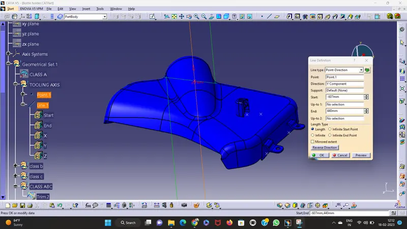
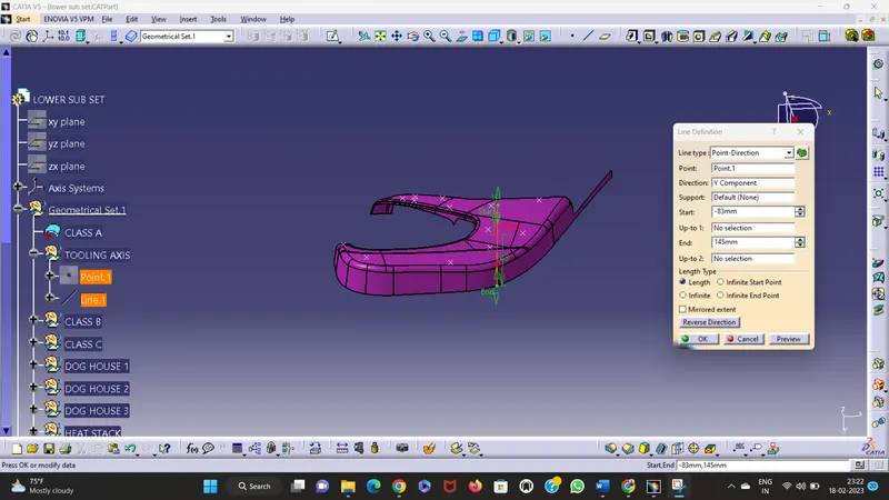
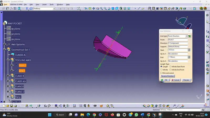
3.TOOLING AXIS CREATION :
The steps to create the tooling axis:
-
Create a Part Design
-
Define the Parting Line
-
Insert Parting Line
-
Define Tooling Axis
-
Verify Tooling Axis
-
Design Mold Cavity and Core
3.1 CREATING THE TOOLING AXIS IN ALL 4 THE COMPONENTS :
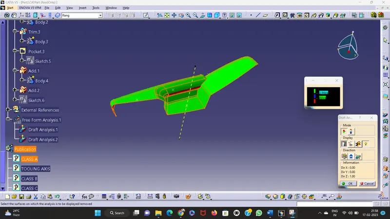
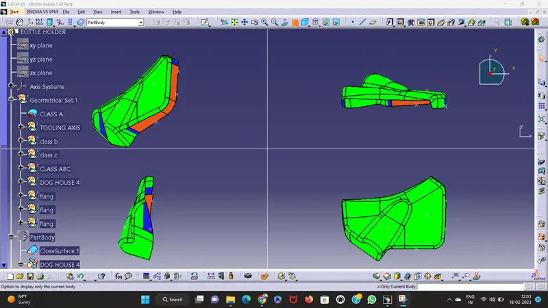
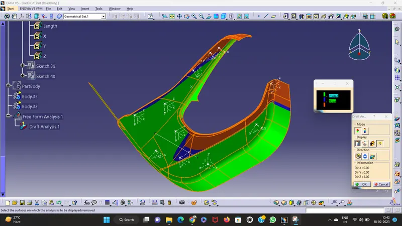
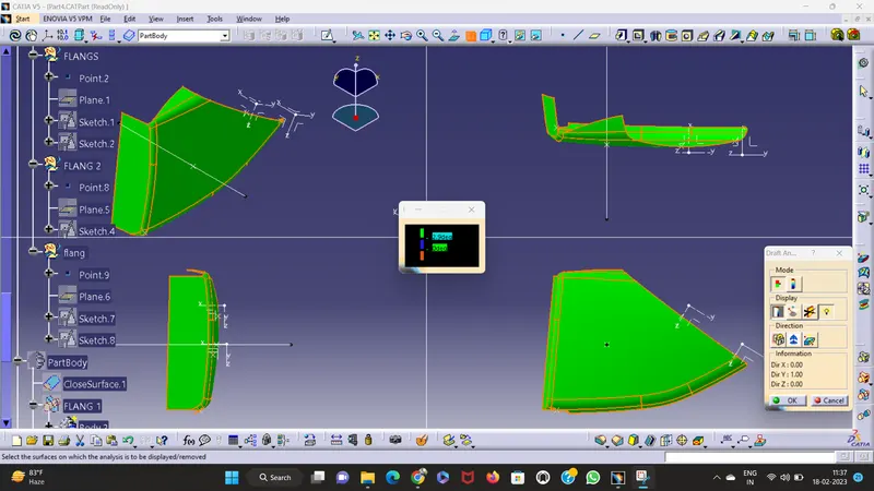
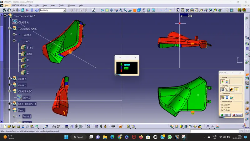
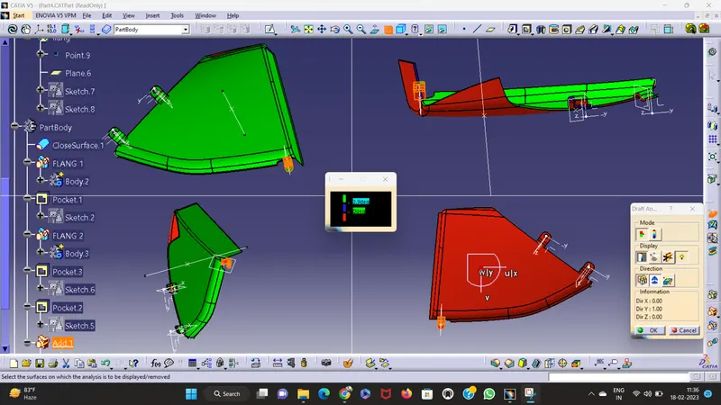
4.CREATING DRAFT ANALYSIS OF CLASS A IN ALL THE 4 COMPONENTS :
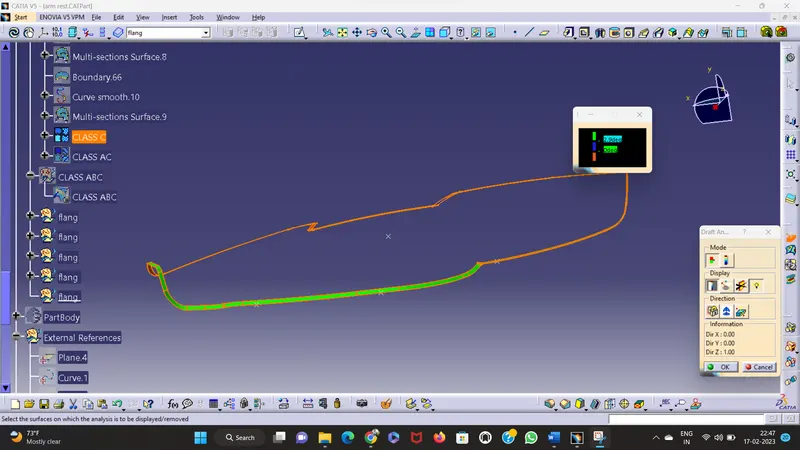
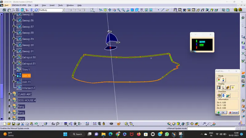
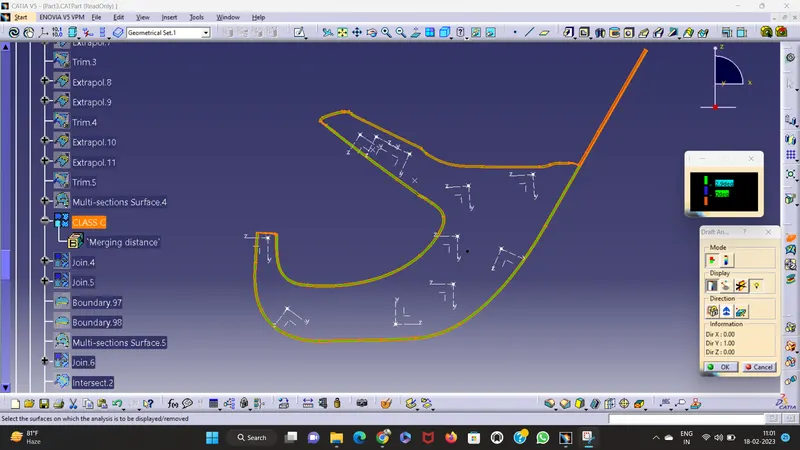
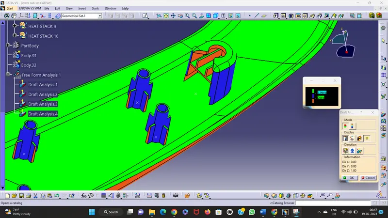
- The minimum draft angle for the faces of the component must be 3 degrees.
- GREEN bar shows the draft angle of 2.9 or above 2.9 degrees.
- The blue bar shows below 2.9 degrees draft angle.
- The other limit being and the RED bar shows the negative draft angle.
- The class A draft analysis as shown in below
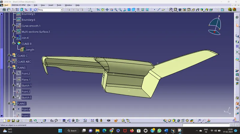
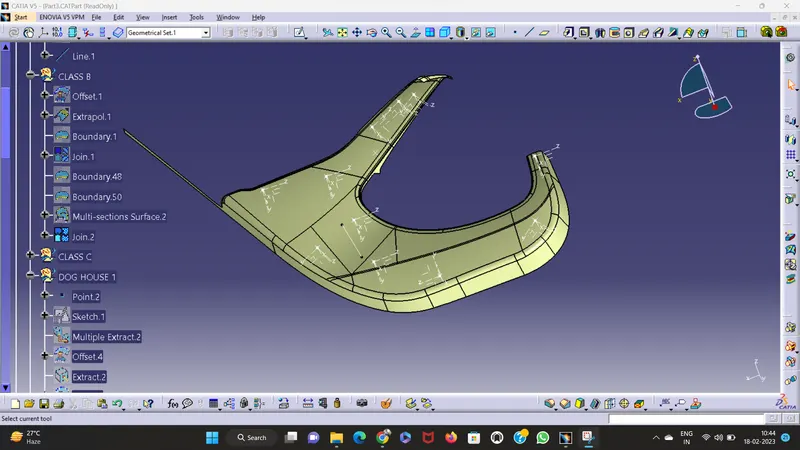
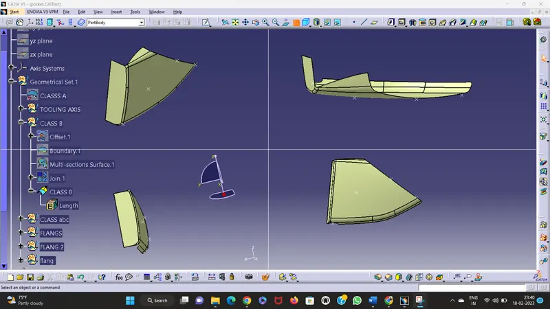
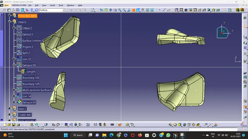
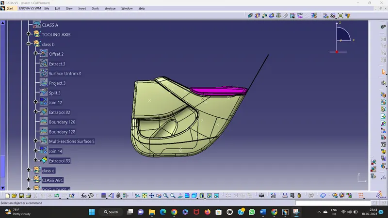
5) B CLASS SURFACE :
- Insert Geometrical set(class B) under Geometrical set-1 and define it as Class B .
- Go to off-set command and click on surface give the value and then click ok.
- click on multi body projection and click on edges of surface and then select one guide curve and click on ok.
- click on trim command to trim the exta surface according the requriment.
- click on edge fillet command and give the fillet at the edges.
CREATING THE B SURFACE USING MASTER SECTION IN ALL THE COMPONENTS :
CREATING THE DOOR ARM REST OF CLASS B SURFACE
CREATING THE LOWER SUBSTRATE OF CLASS B SURFACE
CREATING THE MAP POCKET CLASS B SURFACE
CREATING THE BOTTLE HOLDER OF CLASS B SURFACE
OVERALL CLASSES B SURFACES :
6) C CLASS SURFACE :
- Insert geometrical set under(Geometric Set 1) and click on ok.
- click on boundary command and click in edge of the surface and give the limit and click on ok.
- click on draft command and give the draft angle and give the value of 2.9 and click on ok.
- sweep the class c surface as shown in below.
- Extrapolate the unjoined surfaces and trim them.
CREATING THE DOOR ARM REST OF CLASS C SURFACE :
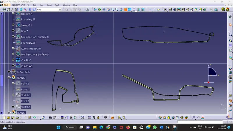
CREATING THE LOWER SUBSTRATE OF CLASS C SURFACE :
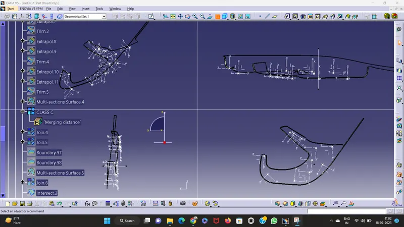
CREATING THE MAP POCKET OF CLASS C SURFACE :
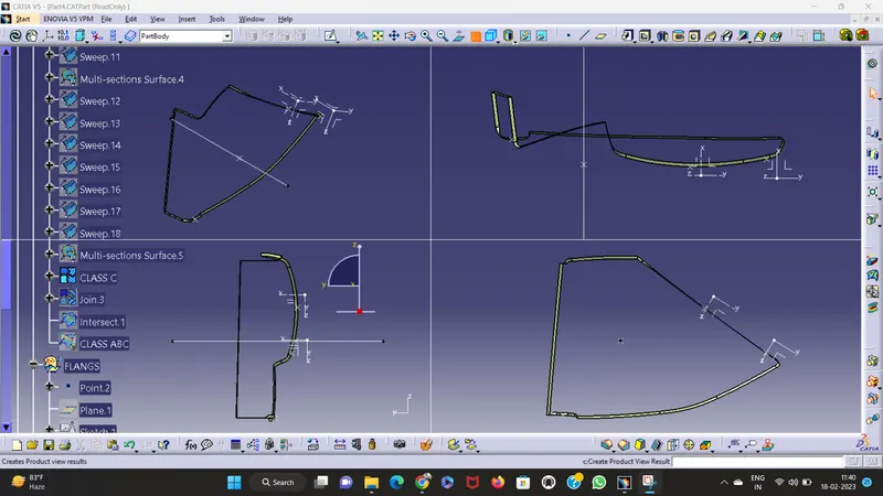
CREATING THE BOTTLE HOLDER OF CLASS C SURFACE
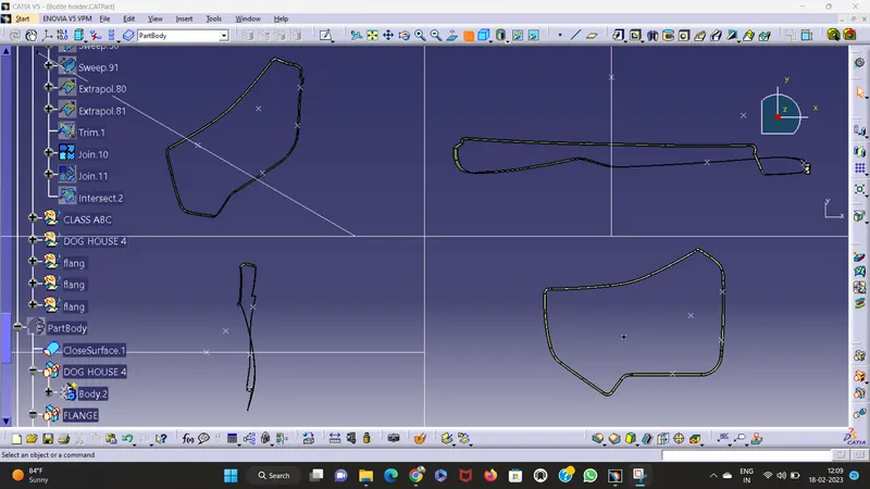
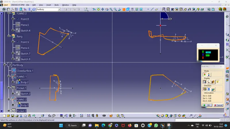
C DRAFT ANALYSIS
7. ADD ALL THE ABC SUFACES :
CREATING THE DOOR ARM REST OF CLASS ABC SURFACE
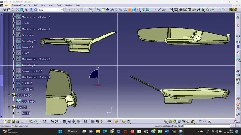
CREATING THE LOWER SUBSTRATE OF CLASS ABC SURFACE
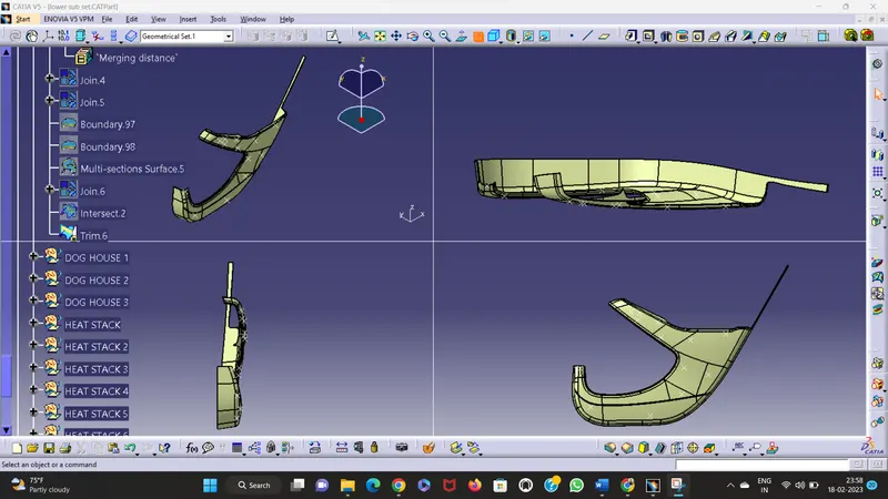
CREATING THE MAP POCKET OF CLASS ABC SURFACE
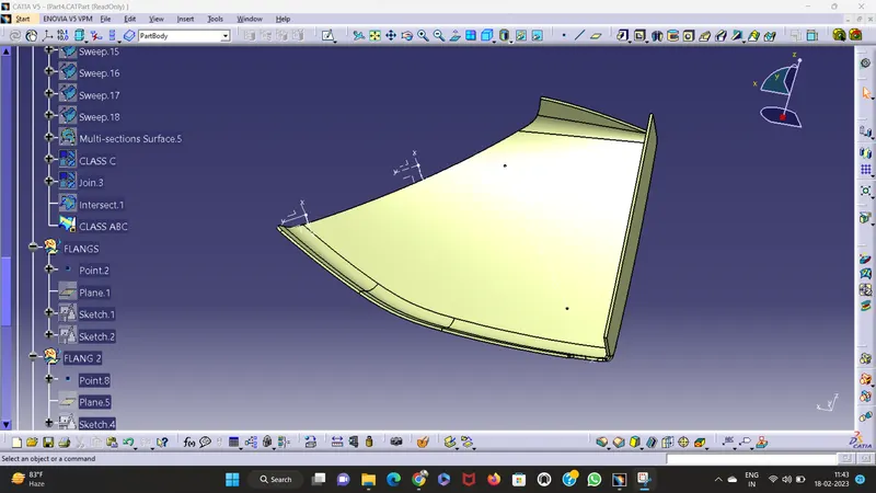
CREATING THE BOTTLE HOLDER OF CLASS ABC SURFACE
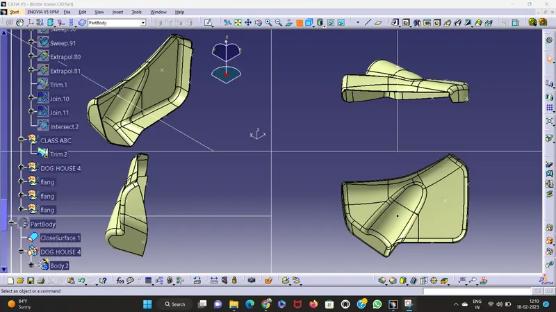
8.CREATING THE MAIN BODY OF ALL THE 4 COMPONENTS
CREATING THE DOOR ARM REST SOLID BODY :
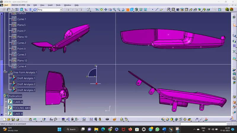
CREATING THE LOWER SUBSTRATE SOLID BODY :
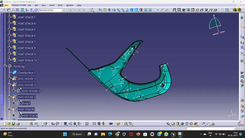
CREATING THE MAP POCKET SOLID BODY :
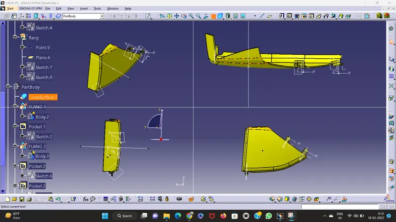
CREATING THE BOTTLE HOLDER SOLID BODY :
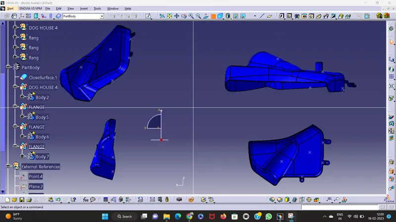
9.DRAFT ANALYSIS OF ALL THE 4 COMPONENTS :
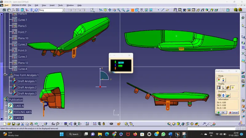
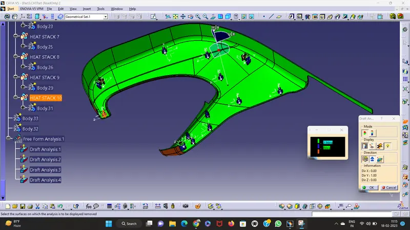
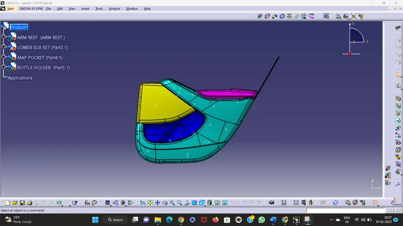
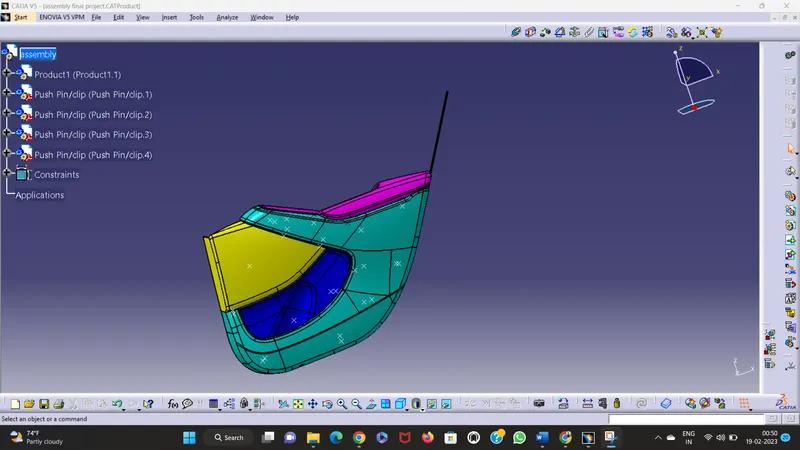
CREATING THE ASSEMBLY OF ALL THE 4 COMPONENTS :
- Open a new assembly document in CATIA V5.
- Create a new product and save it.
- Import the parts (Door arm rest, Lower substrate, Map pocket, Bottle holder) into the assembly.
- Place the parts in the desired position and orientation by using the Move and Rotate functions.
- Add constraints to the parts to restrict their movement relative to each other. Examples of constraints include coincident, concentric, and parallel constraints.
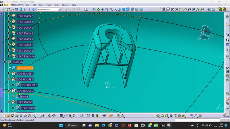
DOG HOUSE :
- Open a part file in CATIA V5.
- Enter sketching mode by clicking on the Sketcher icon in the toolbar.
- Draw a rectangle as the base of the dog house using the Line command.
- Draw a smaller rectangle inside the first rectangle using the Offset command to represent the wall thickness of the dog house.
- Draw a triangle on top of the smaller rectangle to represent the roof of the dog house using the Line command.
- Use the Trim command to trim the lines of the roof that overlap with the walls of the dog house.
- Draw a circle for the entrance of the dog house using the Circle command.
- Use the Trim command to trim the line segments of the smaller rectangle and the triangle that overlap with the circle.
- Use the Extrude command to extrude the sketch into a 3D model, specifying the extrusion depth as required.
- Add fillets to the edges of the dog house using the Fillet command.
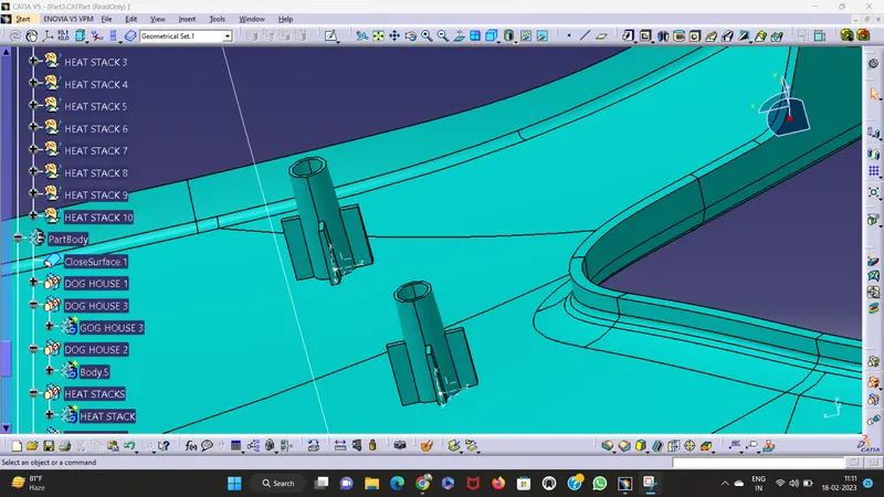
HEAT STAKES:
-
Open a new part file in CATIA V5.
-
Create a new sketch and use the Line command to draw the shape of the heat stake.
-
Draw a small circle at the center of the shape using the Circle command.
-
Use the Pad command to extrude the shape to the desired height.
-
Create a new sketch on the top face of the heat stake and draw a circle at the center of the top face.
-
Use the Pad command to extrude the circle to the desired height, creating a post on top of the heat stake.
-
Create a new sketch on the top face of the post and use the Line command to draw the outline of the top of the post.
-
Use the Trim command to trim the excess lines of the outline and create a closed profile.
-
Use the Pad command to extrude the profile to the desired height, creating a flat surface on top of the post.
FLANGES:
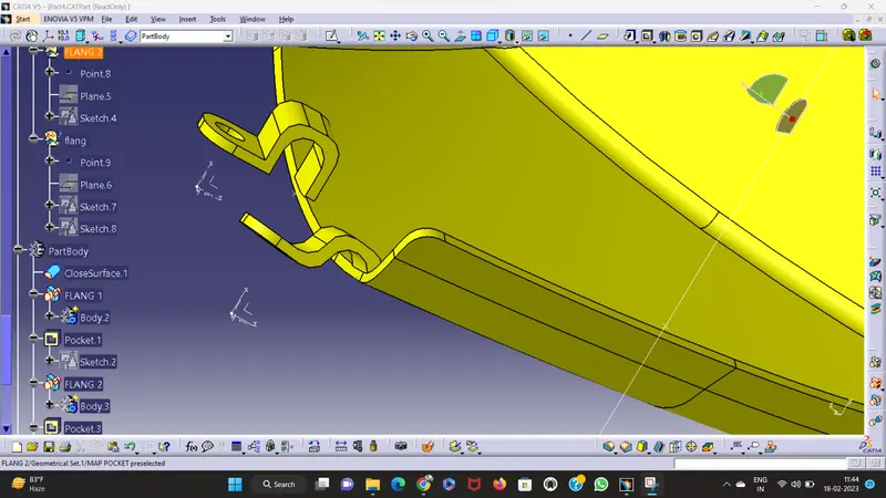
To draw a flange in CATIA V5, follow these steps: draw the outer and inner profiles using the Line and Offset commands, respectively. Extrude the outer profile using the Pad command, and then remove material from the center of the flange using the Pocket command. Add fillets and chamfers to the edges of the flange, and add any necessary holes and details. Finally, save the file and export it to the desired format.
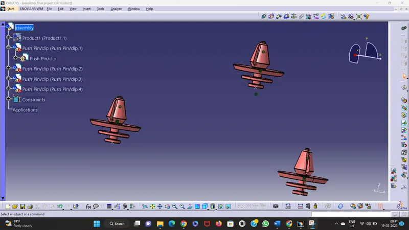
PUSH PIN/CLIPS:
- Create a new sketch and draw the profile of the push pin/clip.
- Extrude the profile to the desired height using the Pad command.
- Draw the shape of the head on top of the push pin/clip in a new sketch.
- Extrude the head shape to the desired height using the Pad command.
- Create a new sketch on the top face of the head and draw the shape of the retention clip using the Circle or Rectangle command.
- Use the Pocket command to remove the material inside the retention clip and add fillets and chamfers for smooth transitions and easy insertion.
- Add any necessary details or features to the push pin or clip.
DOG HOUSE AND HEAT STACKS ARE DRAFT ANALYSIS
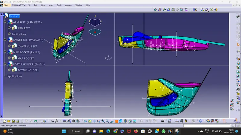
FINAL DOOR TRIM:
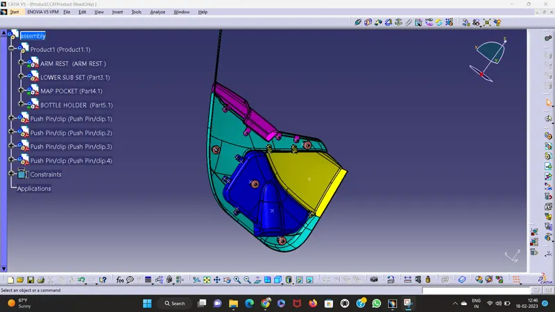
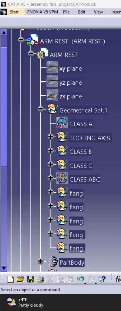
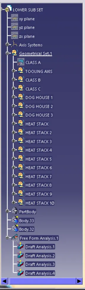
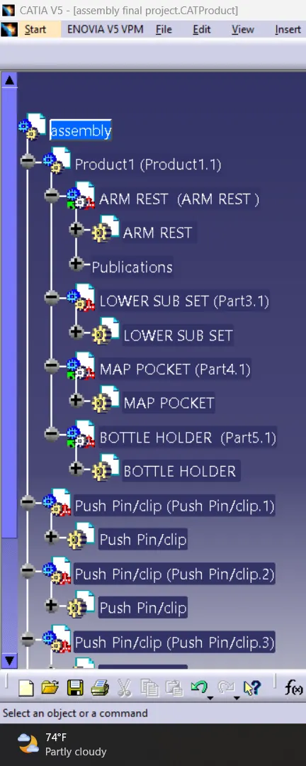
Tree Structure:
Conclusion: Hence the solid body of various parts of the door trim was made successfully with all necessary B-side features following all the design rules and guidelines.