Door Trim Lower with Engineering Features
DOOR TRIM LOWER:
Requirements:
• Creating of Tooling axis with a draft angle.
• Creation of surfaces like Class B and C to form a solid component.
• Perform Draft analysis to the Class A,B & C surfaces and Solid model.
Draft:
The Draft is an amount of taper Provided for the Casting parts or mould parts. it is perpendicular to the parting line in moulding.The main advantage of the draft angle is to release the Part easily from the mould.
Tooling Axis creation:
- It is the direction where the mould and cavity to be open. Selecting the direction of the tooling axis depends on the way at which components can be easily ejected.
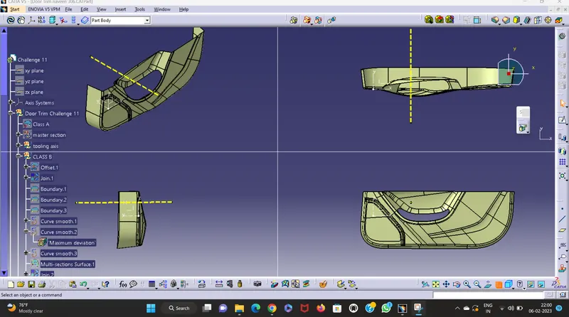
- The most easily ejectable direction is nearly close to the Z direction,(might be inclined to it) so we have made a sketch on the YZ plane of Axis System.
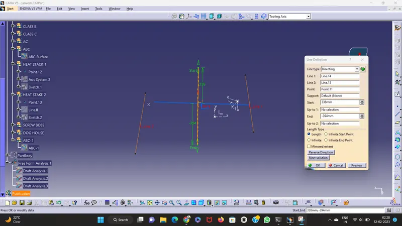
- To create a bisecting line considering the 2 faces which might be difficult to be tooled.
- One more sketch is created on the ZX plane of Axis System for considering the lone side face for tooling direction.
- A line is drawn with an angle to the side faces of the component so that with the resultant tooling axis the side face is cleared.
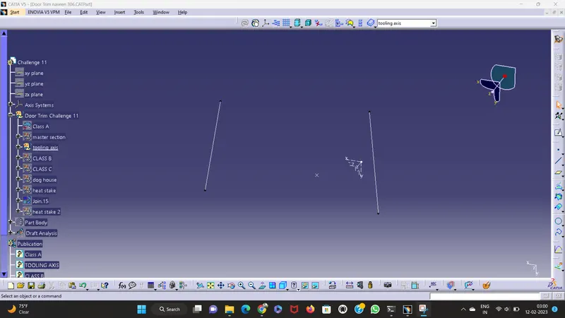
Then the resultant tooling axis is created using the bisecting method.
Draft Analysis:
Class A Surface :
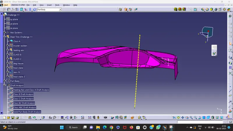
Draft Analysis:
- The minimum draft angle for the faces of the component must be 3 degrees.
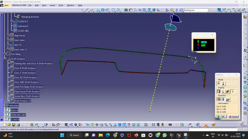
- GREEN bar shows the draft angle of 2.9 or above 2.9 degrees.
- The blue bar shows below 2.9 degrees draft angle.
- The other limit being and the RED bar shows the negative draft angle.
- The class A draft analysis as shown in below
CREATION OF CLASS-B SURFACE:
- Insert Geometrical set(class B) under Geometrical set-1 and define it as Class B .
- Go to off-set command and click on surface give the value and then click ok.
- click on multi body projection and click on edges of surface and then select one guide curve and click on ok.
- click on trim command to trim the exta surface according the requriment.
- click on edge fillet command and give the fillet at the edges.
- Publish Class B.
CREATION OF CLASS-C SURFACE:
- Insert geometrical set under(Geometric Set 1) and click on ok.
- click on boundary command and click in edge of the surface and give the limit and click on ok.
- click on draft command and give the draft angle and give the value of 2.9 and click on ok.
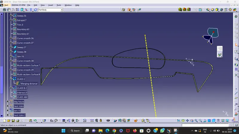
- sweep the class c surface as shown in below.
- Extrapolate the unjoined surfaces and trim them.
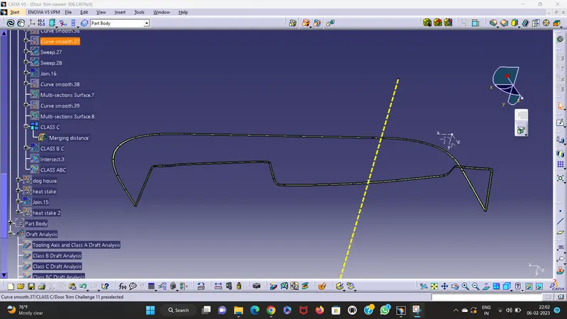
- Class C surface Draft analysis as shown in below figure.
- After joining Publish Class C.
CREATION OF CLASS-A,B,C SURFACE:
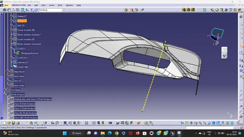
- Click on join command to join the class A, class C, class B to make it as a complete surface model and Publish ABC.
CREATION OF SOLID:
- Click on start and click on mechanical design and then part design.
- select part body, click on define part body.
- click on close surface and then ok as shown below.
Creation of Dog house:
- click on line command and draw two lines by constraining with axis and then click on ok.
- Insert part body and define the work object.
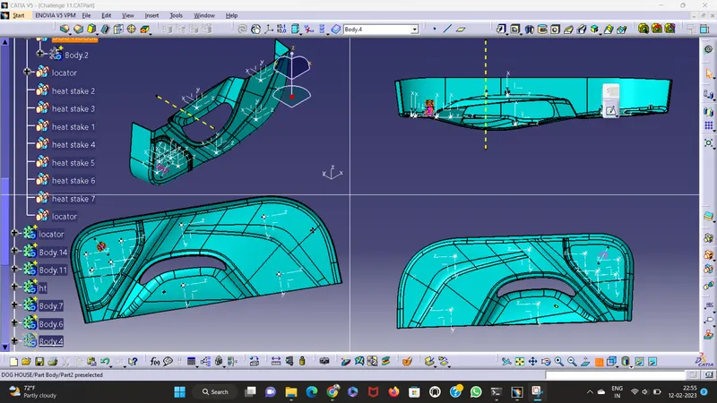
- Draw the dog house with dimensions as shown above by using the commands.
- Use boolean operations to add the dog house to the part body.
- Dog houses are used as a supporting feature.
Creation of Locators:
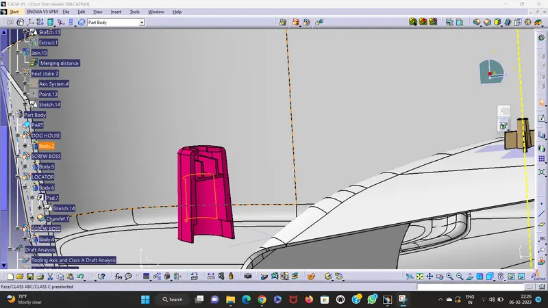
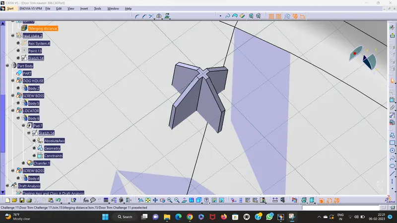
- Locators are 4-way locators.
- click on Rectangle command.
- Sketch the 2D part and Create a body.
- click on pad command--and give the thickness of surface and click on ok.
- Click on draft angle command to make it to the requried shape.
- Use boolean operations to add to the part body.
- change the add to union trim to remove extra faces.
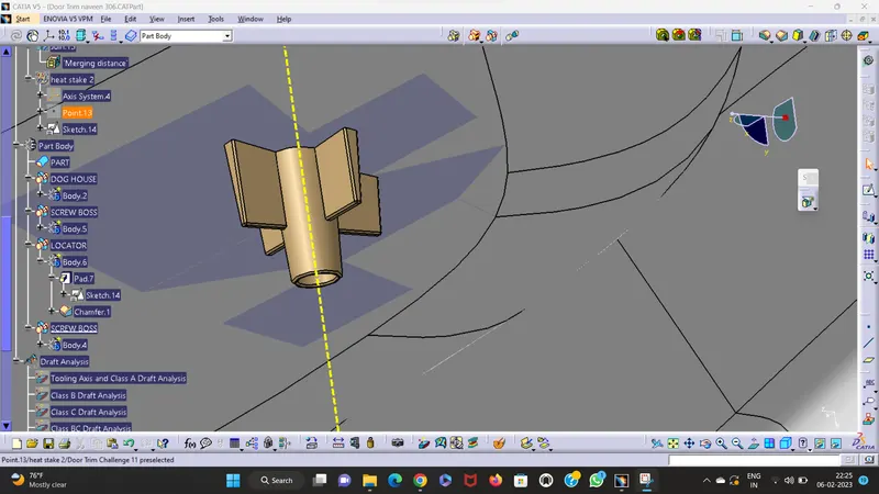
Creation of Heat Stakes:
- These heat stakes will enter the mating component and using a heat staking machine.
- Thus all degrees of freedom are arrested.
- The door applique is fixed on to the door surface with the help of locators and heat stakes.
- So these locators and heat stakes restrict all these degrees of freedom.
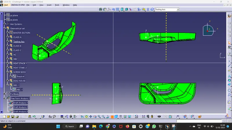
DRAFTING ANALYSIS ON SOLID SURFACE:
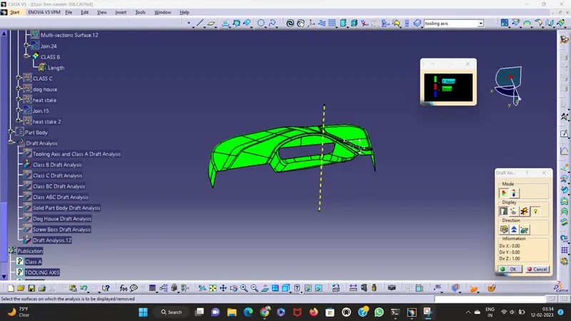
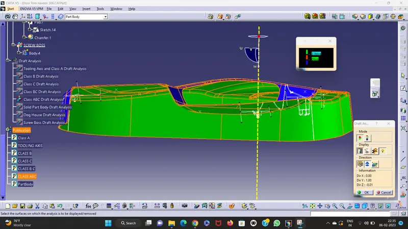
- Change the view into materialistic mode and Go to insert and click on analysis and then feature draft
analysis. - Drag the compass to the tooling axis as shown in figure.
- click on compass in the dialog box---drag some distance---lock it---select the surface with respect to the tooling axis.
- the entire surface is appear in green colour the drafting is correct. if not do corrections on it.
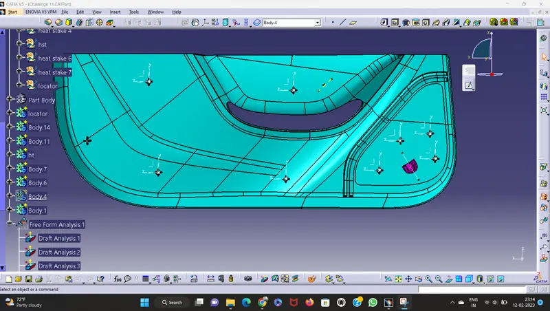
Conclusion: Hence the solid body of door trim lower was made successfully with all necessary Engineering features