Modelling and simulation of flow through a flowbench
Solution:
AIM:
Modelling and simulation of flow through a flowbench
PROJECT:
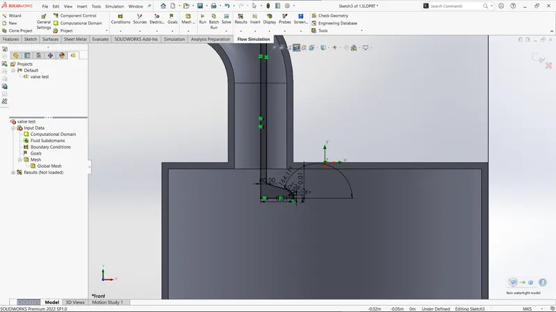
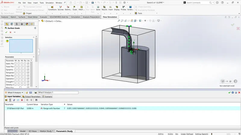
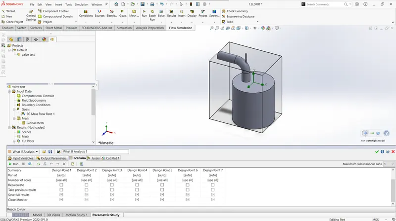
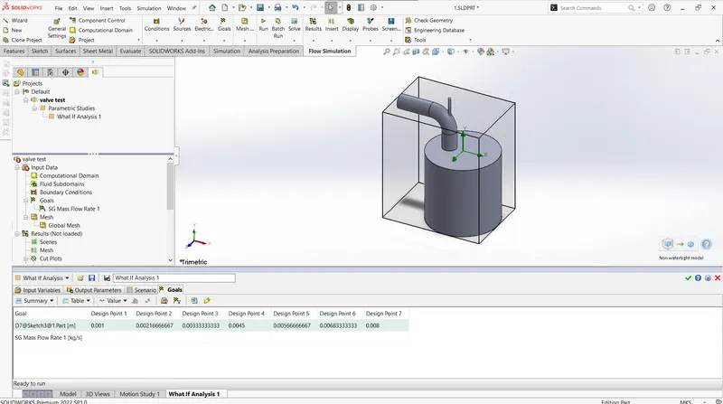
For this project, you will create a 3D model of a flow bench and run flow analysis. You will be obtaining a plot of lift vs mass flow rate
You need to do the following
- Grid dependence test
- For three grids run your simulation at a particular valve lift and explain your results
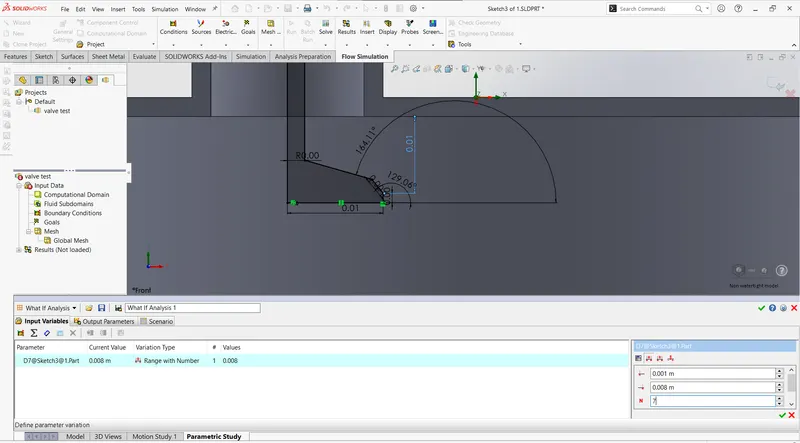
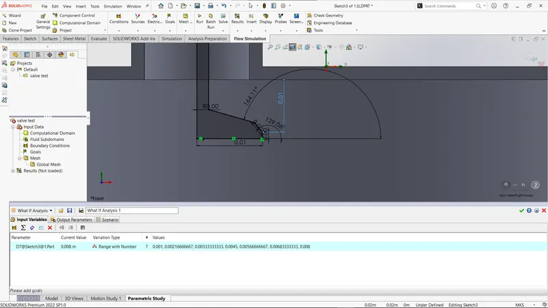
- Effect of valve lift on mass flow rate
- Once you have decided the best grid, run a parametric sweep to show the effect of valve lift on mass flow rate
INTRODUCTION:
Flowbenches are essential tools in the field of fluid dynamics and aerodynamics. They are used to evaluate the flow performance of various components such as cylinder heads, intake manifolds, and exhaust systems. This report focuses on the application of SolidWorks, a widely used Computer-Aided Design (CAD) software, for modelling and simulating flow through a flowbench. The aim is to analyze the flow behavior and characteristics, providing valuable insights for product development and optimization.
SolidWorks Flow Simulation is a powerful computational fluid dynamics (CFD) software that is used to simulate and analyze fluid flow and heat transfer in various engineering applications. It is a comprehensive tool that is seamlessly integrated into the SolidWorks CAD environment, allowing engineers to perform fluid flow analysis directly on their 3D models.With SolidWorks Flow Simulation, engineers can gain insights into the behavior of fluids, such as liquids and gases, and study how they interact with their surrounding environment. By simulating fluid flow and heat transfer, engineers can optimize designs, improve product performance, and make informed decisions before manufacturing or implementing a system.The software offers a wide range of capabilities, including steady-state and transient flow analysis, laminar and turbulent flow modeling, conjugate heat transfer analysis, and multiphase flow simulations. It provides a user-friendly interface that allows engineers to define the geometry, set up boundary conditions, and specify fluid properties easily.
SolidWorks Flow Simulation utilizes the finite volume method, which discretizes the domain into a finite number of control volumes. It then solves the governing equations of fluid flow, including the continuity equation, momentum equations, and energy equation, to calculate fluid velocities, pressures, temperatures, and other relevant parameters.
The software offers advanced visualization tools to help engineers interpret and analyze the simulation results effectively. It provides detailed data on fluid flow patterns, pressure distributions, temperature gradients, velocity vectors, and other important quantities. Engineers can use this information to evaluate the performance of their designs, identify potential issues, and optimize their systems.SolidWorks Flow Simulation finds applications in a wide range of industries, including automotive, aerospace, HVAC (Heating, Ventilation, and Air Conditioning), electronics cooling, chemical processing, and more. It enables engineers to validate and optimize their designs early in the development process, reducing the need for costly physical prototypes and iterations.
Basic Theory
SolidWorks Simulation is a finite element analysis (FEA) software integrated within the SolidWorks CAD environment. It allows engineers to simulate and analyze the structural behavior of their designs, ensuring their performance, reliability, and safety. Here are some basic theories underlying SolidWorks.
Methodology:
The following steps were undertaken to model and simulate flow through a flowbench using SolidWorks:
a. Geometry Creation: A detailed 3D model of the flowbench was created in SolidWorks. This model incorporated all the relevant components, including the inlet, outlet, test section, and various flow measurement devices.
b. Mesh Generation: The flowbench model was meshed to discretize the fluid domain, allowing for the simulation of fluid flow. An appropriate mesh density was chosen to ensure accurate results while maintaining computational efficiency.
c. Boundary Conditions: The necessary boundary conditions were applied, including the inlet velocity profile, pressure conditions, and appropriate constraints at the walls and outlets.
d. Fluid Flow Simulation: The simulation was performed using SolidWorks Flow Simulation module, which employs Computational Fluid Dynamics (CFD) algorithms. These algorithms solve the governing Navier-Stokes equations to predict the fluid flow behavior within the flowbench.
e. Post-Processing: After the simulation was completed, post-processing was conducted to analyze and interpret the results. This involved visualizing velocity vectors, pressure distributions, and other relevant flow parameters.
3. Results and Findings:
The simulation provided valuable insights into the flow behavior within the flowbench. Some of the key findings include:
a. Velocity Distribution: The simulation results illustrated the variation of velocity across different sections of the flowbench, highlighting regions of high and low velocity.
b. Pressure Distribution: The pressure distribution was mapped to identify potential areas of pressure drop or stagnation, which could impact the overall performance.
c. Flow Patterns: The simulation allowed visualization of flow patterns, turbulence, and vortices, aiding in understanding the flow characteristics.
d. Flow Uniformity: Flow uniformity within the test section was assessed, which is crucial for accurate testing of components.
RESULT:
The use of SolidWorks for modelling and simulating flow through a flowbench proved to be effective and efficient. The software's user-friendly interface and powerful simulation capabilities enabled a comprehensive analysis of the flow behavior.
However, it is essential to acknowledge certain limitations. The accuracy of the simulation heavily relies on the assumptions made during the modelling process and the selected turbulence model. Experimental validation of the simulation results is necessary to ensure reliability.
5. Conclusion:
In conclusion, this report demonstrates the application of SolidWorks for modelling and simulating flow through a flowbench. The results obtained from the simulation provide valuable insights into the flow behavior, aiding in product development and optimization.
By combining the power of SolidWorks with experimental validation, engineers and researchers can enhance their understanding of fluid flow phenomena, ultimately leading to improved designs and more efficient systems.
References:
- Skill-lync
- chatgpt
- solidworks simulation