Modelling and simulation of flow through a flowbench
Aim : To create an run a flow analysis of a 3D modal Flowbench
Objective :
- Run a grid dependence test for three different level of initial mesh
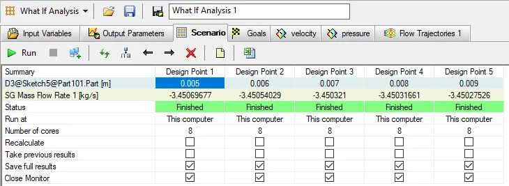
- Run a parametric sweep to show the effect of valve lift on mass flow rate
Theory
What is an Flowbench? An air flow bench is a device used for testing the internal aerodynamic qualities of an engine component. It is used primarily for testing the intake and exhaust ports of cylinder heads of internal combustion engines. It is also used to test the flow capabilities of any component such as air filters, carburetors, manifolds or any other part that is required to flow gas. A flow bench is one of the primary tools of high performance engine builders.
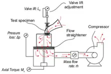
A flow bench consists of an air pump, a metering element, pressure and temperature measuring instruments such as manometers, and various controls. The test bench is attached in series with the pump and measuring element and air is pumped through the whole system. Therefore, all the air passing through the metering element also passes through the test bench. Because the volume flow rate through the metering element is mesured and the flow through the test bench also measured. The mass flow rate can be calculated using the pressure and temperature data to calculate air densities, and multiplying by the volume flow rate.
Valve lift : The valve lift is the distance by which the valve is raised from its seated position when it is fully opened.
Mass flow rate : The mass flow rate is the mass of a fluid passing per unit time. In other words, the mass flow rate is defined as the rate of movement of fluid pass through a unit area. The mass flow is directly dependent on the density, velocity of the fluid and area of cross-section.
Simulation Setup :
Parameters
Analysis Type : Internal
Fluid : Air
Pressure : 101325 Pa
Temperature :293.2 K
Flow type : Laminar & turbulence
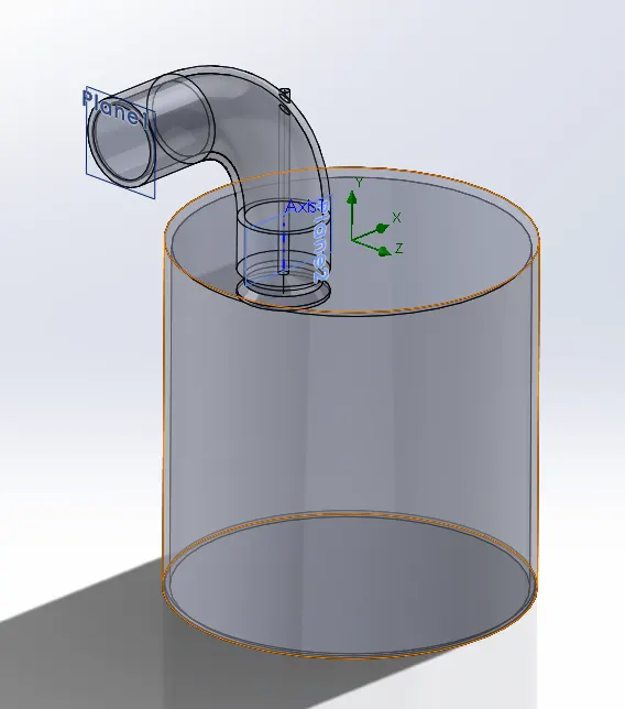
Modal
Procedure
- Design a Flowbench as shown above with suitable dimension
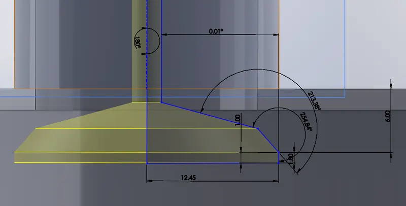
- Fully define the sketch of the valve as shown above
- Run a grid dependence test for three different level of initial mesh (3, 5, 7)
- Choose a suitable level of initial mesh and setup a parametric studies
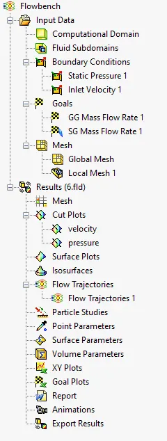
- Insert the boundaries, goals, cut plot, and flow trajectories
- Run the parametric studies with the valve lift as an input
- Obtain effect of valve lift on mass flow rate graph
Result
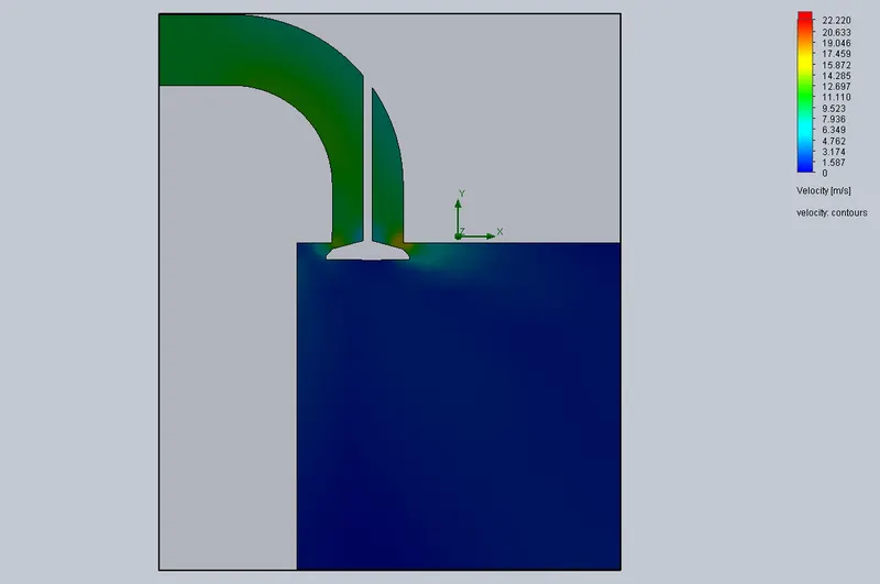
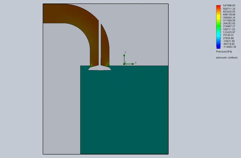
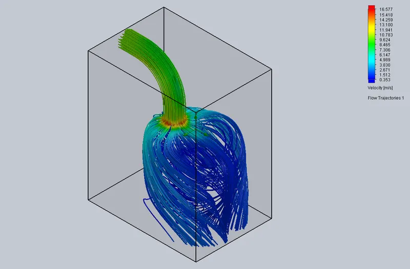
Grid dependence test
(mesh level = 3)
Plots: velocity pressure trajectory
(mesh level = 5)
Plots: velocity pressure trajectory
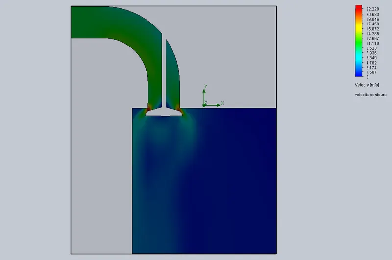
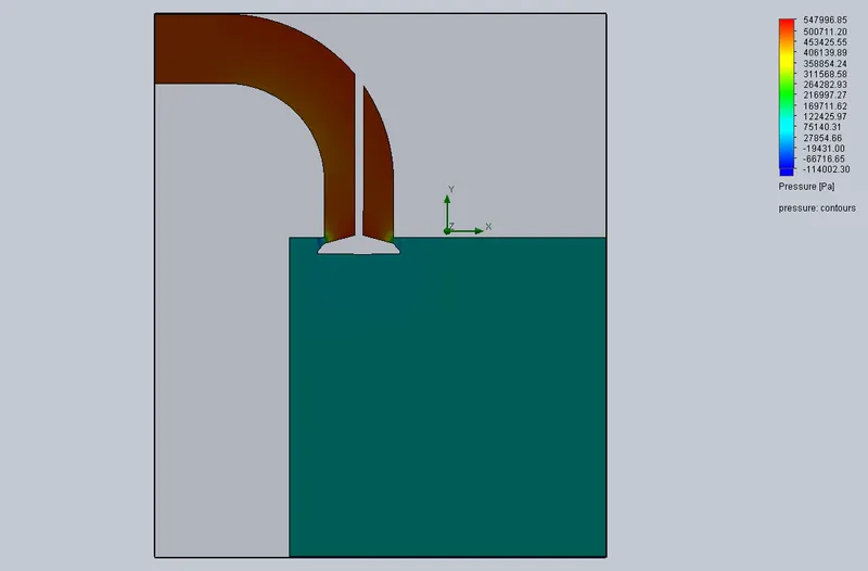
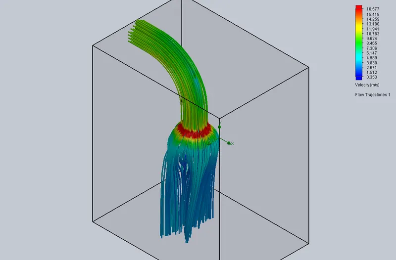
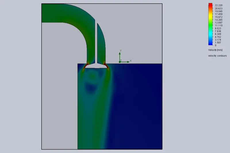
(mesh level = 7)
Plots: velocity pressure trajectory
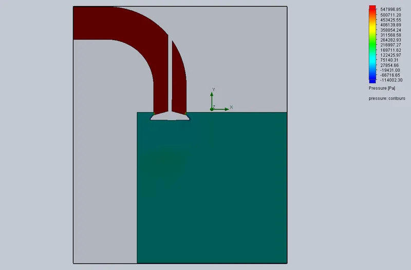
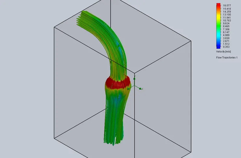
Case Study 1 (Valve Lift = 0.005 m)
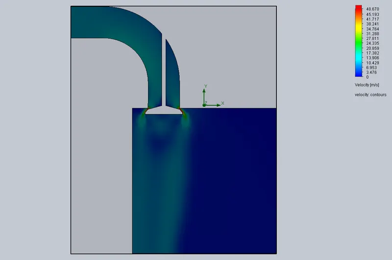
Velocity plot
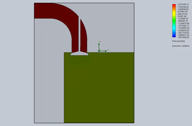
pressure plot
Trajectory plot
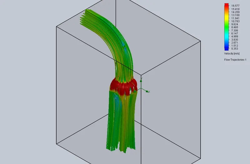
Observation : The maximum velocity = 48.670 m/s , the maximum pressure = 2227026 Pa ,
the mass flow rate = -3.4507 kg/s
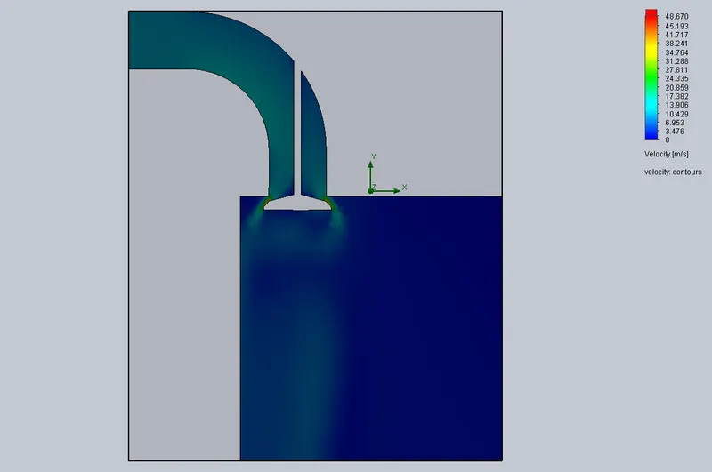
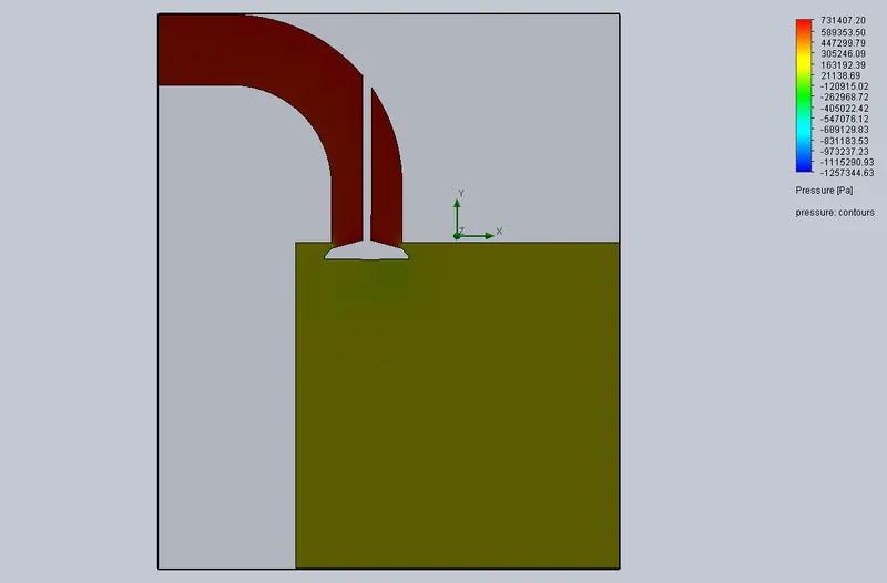
Case Study 1 (Valve Lift = 0.006 m)
Velocity plot
pressure plot
Trajectory plot
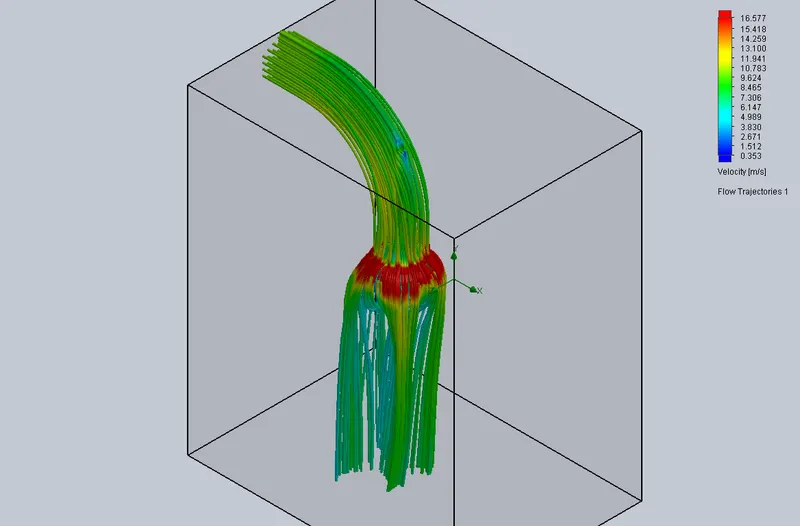
Observation : The maximum velocity = 48.670 m/s, the maximum pressure = 731407 Pa,
the mass flow rate = -3.4505 kg/s
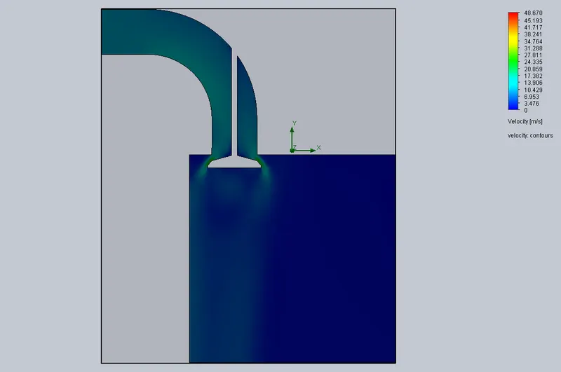
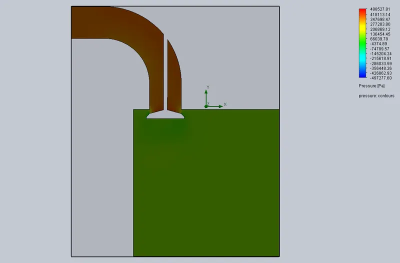
Case Study 1 (Valve Lift = 0.007 m)
Velocity plot
pressure plot
Trajectory plot
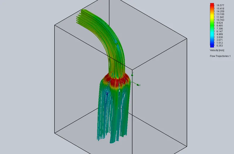
Observation : The maximum velocity = 48.670 m/s, the maximum pressure = 480527 Pa,
the mass flow rate = -3.4503 kg/s
Case Study 1 (Valve Lift = 0.008 m)
Velocity plot
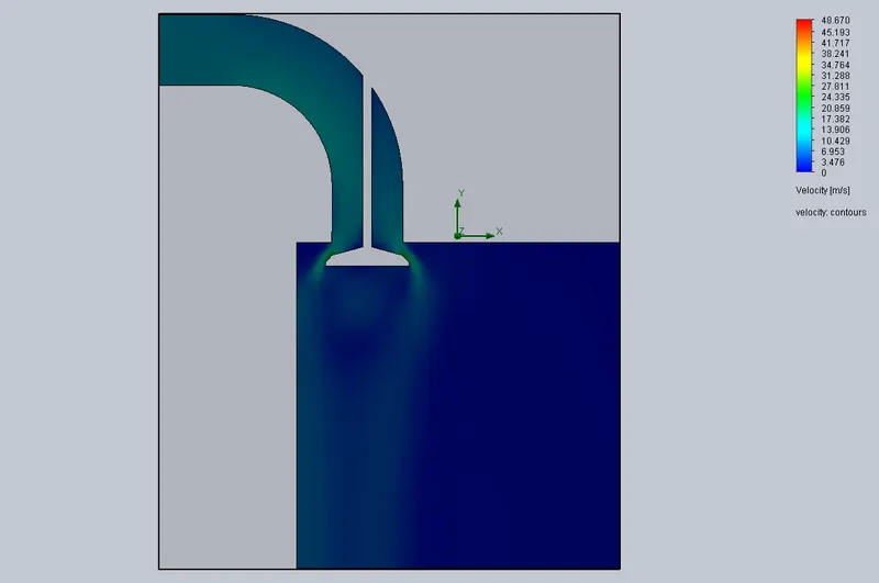
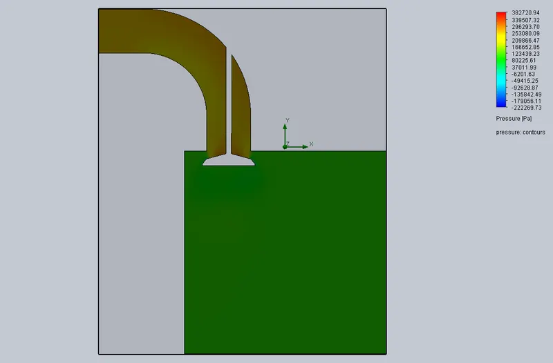
pressure plot
Trajectory plot
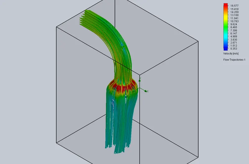
Observation : The maximum velocity = 48.670 m/s, the maximum pressure = 382720 Pa,
the mass flow rate = -3.4503 kg/s
Case Study 1 (Valve Lift = 0.009 m)
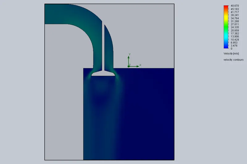
Velocity plot
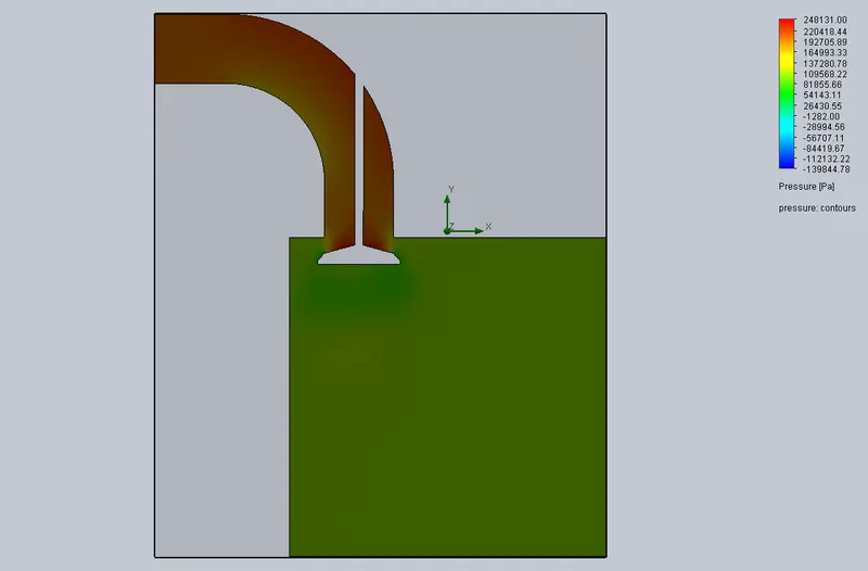
pressure plot
Trajectory plot
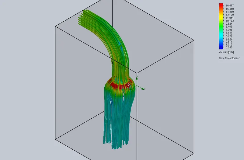
Observation : The maximum velocity = 48.670 m/s, the maximum pressure = 248131 Pa,
the mass flow rate = -3.4503 kg/s
Plot for mass flow rate for different valve lift
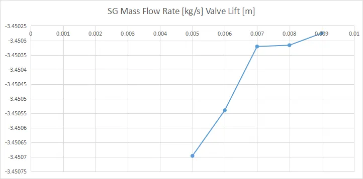
Parametric study result

Conclusion/Observation
- From the graph, we can say that when the valve lift increases the velocity increases .
- When the valve is closed the pressure in the pipe is maximum and when the valve lift increses the the pressure decreases.
- From the parametric result, we can say that when the valve lift increses the mass flow rate increases.