Modelling and simulation of flow through a flowbench
MODELING AND SIMULATION OF FLOW THROUGH A FLOWBENCH
OBJECTIVE For this project, you will create a 3D model of a flow bench and run flow analysis. We will be obtaining a plot of lift vs mass flow rate
INTRODUCTION
FLOWBENCH An air flow bench is a device used for testing the internal aerodynamic qualities of an engine component and is related to the more familiar wind tunnel.
It is used primarily for testing the intake and exhaust ports of cylinder heads of internal combustion engines. It is also used to test the flow capabilities of any component such as air filters, carburetors, manifolds or any other part that is required to flow gas. A flow bench is one of the primary tools of high performance engine builders, and porting cylinder heads would be strictly hit or miss without it.
A flow bench consists of an air pump of some sort, a metering element, pressure and temperature measuring instruments such as manometers, and various controls
VALVE LIFT The valve lift is the distance by which the valve is raised from its seated position when it is fully opened.
PROCEDURE
- Modelling the flowbench (as suitable dimension)
2.Dimension given to the valve sketch for fully defined sketch.
3.Applying lid on both inlet and outlet port of the flowbench
Create new project and apply new setup for wizard as
i.internal flow
ii.air as working fluid
iii. rest as default
4.appling global mesh setting 04 as well as local mesh setting 05 .
Local mesh for the valve handle and base surface so the mesh will redefine across the surface for getting better visualization
5.adding boundary condition
Environment pressure at inlet @ 501325 pa.
Static pressure at outlet @ 101325 pa
- adding a surface goal of mass flow rate on outer lid 2
7.adding cut plot in fornt plane for velocity and pressure
8.adding a flow trajectory from input face with 100 pipe as well as 100 arrow between the inlet and the outlet lid2
9.we two parametric study in which
i.input parameter as a different global mesh value as 4 , 5 and 7
ii.input parameter as a valve lift for the value of 4mm,5mm,6mm,7mm,8mmand 9mm. (global mesh size is 5)
RESULT
STUDY 01 GRID DEPENDENCY TEST
NOTE :- HERE WE NEED TO STOP THE CALCULATION FOR THE GLOBAL MESH SIZE 07 AFTER A 100 ITRATION BECAUSE IT TAKES TOO MUCH TIME FOR CALCULATION
THESE ARE THE FOLLOWING PLOT
GLOBAL MES VELOCITY PRESSURE TRAJECTORY
04
05
07
MASH FLOW RATE GRAPH
STUDY 02 PARAMETRIC STUDY
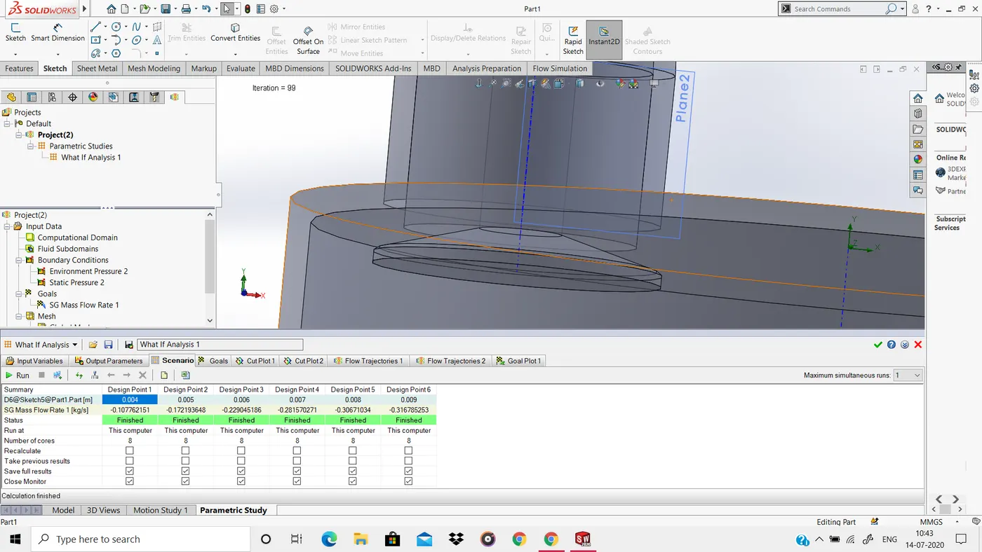
AT 04 MM
VLOCITY PLOT
PRESSURE PLOT
TRAJECTORIES
AT 05 MM
VLOCITY PLOT
PRESSURE PLOT
TRAJECTORIES
AT 06 MM
VLOCITY PLOT
PRESSURE PLOT
TRAJECTORIES
AT 07 MM
VLOCITY PLOT
PRESSURE PLOT
TRAJECTORIES
AT 08 MM
VLOCITY PLOT
PRESSURE PLOT
TRAJECTORIES
AT 09 MM
VLOCITY PLOT
PRESSURE PLOT
TRAJECTORIES
GRAPH FOR VARIATION OF MASS FLOW RATE WITH VALVE LIFT
CONCLUSION :-
- FROM THE GRAPH, WE SAY THAT AS THE VALVE LIFT INCREASES ,THE INLET VELOCITY INCREASES
- as the valve lift increase , the mass flow rate also increase with decreaseing slop so we can say that after a finite valve life mass flow rate will indepenent of valve lift.
- as we increse the mesh value the curve or countour will get more fine and accurate.