MBD Simulation on IC Engine Valve Train
AIM
today, i am going to create 3D drowing of IC ENGINE VALVE TRAIN component , assemble them in SolidWorks and later we also run the simulation of assembled component and obtain varioud plot like
The contact force between
- Cam and Push Rod
- Pushrod and Rocker Arm
- Rocker Arm and Valve
BASIC INTRODUCTION
VALVE TRAIN
A valvetrain or valve train is a mechanical system that controls operation of the intake and exhaust valves in an internal combustion engine.The intake valves control the flow of air/fuel mixture (or air alone for direct-injected engines) into the combustion chamber, while the exhaust valves control the flow of spent exhaust gasses out of the combusion chamber once combustion is completed.
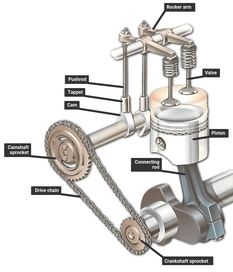
COMPONENT
The valvetrain consists of all the components responsible for transferring the rotational movement of the camshaft into the opening and closing of the intake and exhaust valves.
Cam
The timing and lift profile of the valve opening events are controlled by the camshaft, through use of a carefully shaped lobe on a rotating shaft. The camshaft is driven by the crankshaft and in the case of a four-stroke engine rotates at half the speed of the crankshaft.
Motion is transferred from the crankshaft to the camshaft most commonly by a rubber timing belt,a metallic timing chain or a set of gears.
Pushrod
Pushrods are long, slender metal rods that are used in overhead valve engines to transfer motion from the camshaft (located in the engine block) to the valves (located in the cylinder head). The bottom end of a pushrod is fitted with a lifter, upon which the camshaft makes contact. The camshaft lobe moves the lifter upwards, which moves the pushrod. The top end of the lifter pushes on the rocker arm, which opens the valve.
Rocker arm
A rocker arm is a pivoting lever that pushes on the valve stem. Rocker arms will sometimes be called rocker levers, or just rockers. Depending on the type of valve train, the rotating camshaft lobes will either push directly on the rocker arm, or on the pushrods, which will conduct the motion up to the rocker arm. In an overhead cam engine, the cam follower is built into the rocker arm in the form of a roller.
Valves
A valve is composed of two major sections, the valve head and valve stem. The head of the valve is what allows air into and out of the cylinder. The stem is what gets gets pressed on by the rest of the valve train. At the end of the stem are grooves that keepers will fit into to hold the valve in place. Some engines have only two valves per cylinder, and some have four. The more common number in the heavy duty diesel market is four. These are split evenly between intake and exhaust valves.
VALVE SPRINGS
The camshaft creates an upward force that acts on the rocker arm, which in turn pushes the valve down. But as the cam rotates around, it does not pull the pushrod or rocker arm back with it. Thats why there is a valve spring to create force in the opposite direction and close the valve. The spring will hold the valve closed until the lobe of the camshaft comes around with a greater force and pushes it down.
Valve Seats
The valve seat mates with the valve face to seal the combustion chamber. In addition to the sealing function, the valve seat also removes a significant amount of the heat away from the valves. Two common types of valve seats are the integrally machine valve seat and the valve seat insert.
GIVEN DATA
| Sl.No | CAM Lift (mm) | Speed (RPM) | Material |
| 1 | 3.5 | 1500 | Cast Carbon Steel |
| 2 | 6 | 1500 |
Cast Carbon Steel |
3D MODEL OF PART OF VALVE TRAIN (DIAMENSION AS GIVEN IN PART DRAWING FILE)
link for part drawing file for IC Engine valve train
- CAM
for cam drawing first of all we need to find L
FOR CALCULATION L
Given (in mm)
Cam Lift = 3.5 ......(case I)
Cam Lift = 6 ......(case II)
D1 = 25
D2 = 10
L= ?(to be find out)
CAM LIFT FORMULA
CAM LIFT = (L - R1) +R2
L = CAM LIFT + R1 - R2 ...................eq(1)
putting value of CAM LIFT , R1 & R2 in eq(1) ,we will able to find the value of L for both case,
case (I)
L = CAM LIFT + R1 - R2
L = 3.5 + (25/2) - (10/2)
L = 3.5 + 12.5 - 5
L = 11
case (II)
L = CAM LIFT + R1 - R2
L = 6 + (25/2) - (10/2)
L = 6 + 12.5 - 5
L = 13.5
PUSH ROD
ROCKER ARM
VALVE STEM
VALVE
ASSEMBLY OF IC ENGINE VALVE TRAIN
all component in front plane after applying mate and final assemble resp.
MOTION ANLYSIS :
- CAM ANGULAR SPEED 1500 RPM (CLOCKWISE)
- MATERIAL CAST CARBON STEEL
PROPERTIES
- CONTECT ESTB. MATERIAL STEEL (DRY)
- FRAME 7200FPS
- SPRING STIFFENESS 10N/MM^2 (because if the stiffeness of spring is very less than the valve is not able to bring back due the force applied by the cam is greater it will dominant over spring force so system will distory)
VIDEO LINK
OBSERVATION
1 FOR CAM LIFT 3.5 MM
I) The contact force between CAM AND PUSH ROD
II) The contact force between Pushrod and Rocker Arm
III) The contact force between Rocker Arm and Valve
IV) The contact force between Rocker Arm and Valve IN X DIRECTION
V) LINEAR DISPLACEMENT OF PUSH ROD
VI) LINEAR DISPLACEMENT OF VALVE
2 FOR CAM LIFT 6 MM
I) The contact force between CAM AND PUSH ROD
II) The contact force between Pushrod and Rocker Arm
III) The contact force between Rocker Arm and Valve
IV) The contact force between Rocker Arm and Valve IN X DIRECTION
V) LINEAR DISPLACEMENT OF PUSH ROD
VI) LINEAR DISPLACEMENT OF VALVE
CONCLUSION
- THE CONTACT FORCE BETWEEN THE PART OF IC ENGINE VALVE TRAIN IN 3.5 MM CAM LIFT IS LOWER THAN THECONTACT FORCE BETWEEN THE PART OF HAVEING 6 MM CAM LIFT.
CONTACT FORCE (HAVING 6 MM CAM LIFT) > CONTACT FORCE (3.5MM CAM LIFT)
2.THE DISPLACEMENT OF PUSH ROD AND VALVE HAVING 6 MM CAM LIFT IS HIGHER THAN THE DISP. OF PUSH ROD AND VALVE HAVING 3.5 MM CAMLIFT.
DISPLACEMENT (HAVING 6 MM CAM LIFT) > DISPLACEMENT (3.5MM CAM LIFT)
FROM ABOVE OBSERVATION ,WE CAN SAY THAT THE CONTACT FORCE & DISPLACEMENT ARE DEPEND ON THE CAM LIFT ,HIGHER THE CAM LIFT HIGHER THE CONTACT FORCE AS WELL AS DISPLACEMENT.
4. CONTACT FORCE ARE AT THEIR PEAK WHEN THE CAM LOBE IS AT TOP MOST POSITION.
the contact force between the Rocker arm and valve varies while measuring with respect to the X direction and measuring with respect to magnitude due to varing contact point as well as the rocker arm in circular osillation kind motion on other hand valve is linear motion so there is lose contact. in x direction their is only x component of contact force but in magnitude all component are combined.