MBD Simulation on IC Engine Valve Train
Simulation on IC Engine Valve Train
Aim:
To create and assemble the parts of the IC engine valve train. And then perform the motion study for valve linear motion and contact force for this assembly.
Objective:
- To create and assemble 3D model of the Cam, Push rod, Rocker arm, valve stem and valve.
- To perform motion analysis and simulation on the following cases.
| Sl.No | CAM Lift (mm) | Speed (RPM) | Material |
| 1 | 3.5 | 1500 | Cast Carbon Steel |
| 2 | 6 | 1500 | Cast Carbon Steel |
Obtain the
- Valve Lift.
- The contact force between
- Cam and Push Rod
- Pushrod and Rocker Arm
- Rocker Arm and Valve
THEORY
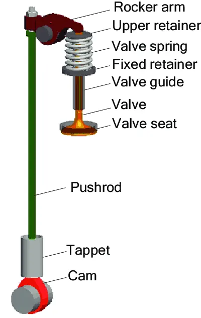
- A valve train is a mechanical system that controls operation of intake and exhaust valve in an I.C. engine.
- Cam lift profile. The ‘cam lift’ is actually an abbreviation of the ‘follower lift at the cam side’.
- The term is usually only meaningful for the pushrod valvetrain where the follower lift has a simple one-dimensional translational motion driven by the cam.
- Note that the cam lift is not equivalent to the contour shape of the cam lobe for the case of a roller follower.
- The cam contour shape refers to the radial distance beyond the cam base circle from the cam centre to any point on the cam lobe profile.
- The cam lift is not equal to the radial distance because the radius of the roller follower is not equal to zero.
- For the pushrod and the direct-acting OHC valvetrains, cam lift or essentially the follower lift is usually used to describe the intended cam profile design, and the actual contour shape of the cam lobe can be calculated once the cam lift profile, and the roller size are specified.
- On the other hand, for some OHC valvetrains.
- It is often more convenient to directly use the actual contour shape of the cam lobe to define the cam profile design.
Camshaft:
- The timing and lift profile of the valve opening events are controlled by the camshaft, through use of a carefully shaped lobe on a rotating shaft.
- The camshaft is driven by the crankshaft and in the case of a four-stroke engine rotates at half the speed of the crankshaft.
- Motion is transferred from the crankshaft to the camshaft most commonly by a rubber timing belt, a metallic timing chain or a set of gears.
Push Rod:
- Pushrods are long, slender metal rods that are used in overhead valve engines to transfer motion from the camshaft (located in the engine block) to the valves (located in the cylinder head).
- The bottom end of a pushrod is fitted with a lifter, upon which the camshaft makes contact.
- The camshaft lobe moves the lifter upwards, which moves the pushrod.
- The top end of the lifter pushes on the rocker arm, which opens the valve.
Rocker arm:
- Depending on the design used, the valves are actuated by a rocker arm, finger or bucket tappet.
- Overhead camshaft engines use fingers or bucket tappets, upon which the cam lobes contact.
- Overhead valve engine use rocker arms, which are actuated by a pushrod and pivot on a shaft or individual ball studs in order to actuate the valves.
Valves:
- Most modern engines use poppet valve type, although sleeve, slide and rotary valves have also been used at times.
- Poppet valves are typically opened by the camshaft lobe or rocker arm and closed by a coiled spring called a valve spring.
- Valve float occurs when the valve spring is unable to control the inertia of the valvetrain at high engine speeds (RPM).
Design of Cam:
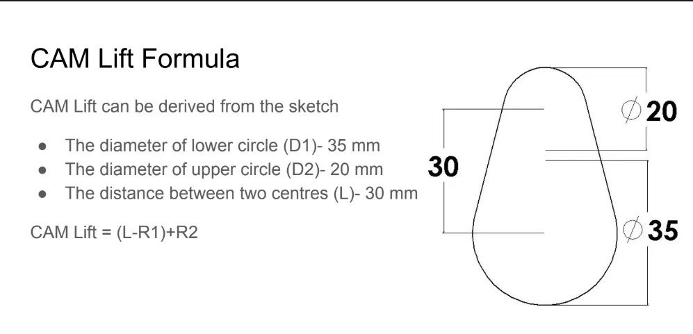
Cam Lift formula:
For Case 1:
- Cam lift = 3.5 mm
- cam lift = (L-R1) +R2
- 3.5 = (L-17.5) +10
- 3.5 = L -7.5
- L = 11 mm
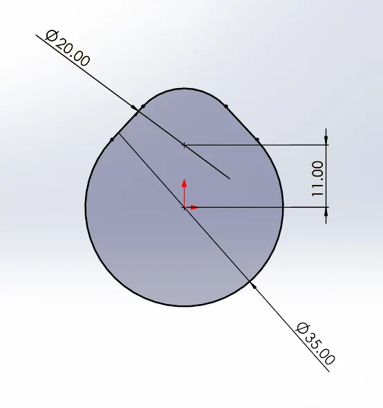
Cam 1 Data:
- Diameter of lower circle (D1) = 35mm
- Diameter of Upper circle (D2) = 20mm
- Distance between the centres (L) = 11 mm
For Case 2:
- Cam lift = 6 mm
- cam lift = (L-R1) +R2
- 6 = (L-17.5) +10
- 6 = L -7.5
- L = 6+7.5
- L = 13.5 mm
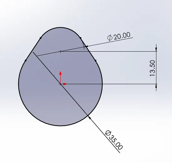
Cam 2 Data:
- Diameter of lower circle (D1) = 35mm
- Diameter of Upper circle (D2) = 20mm
- Distance between the centres (L) = 13.5 mm
Cam Shaft:
case_1
case_2
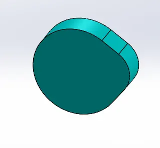
Push Rod:
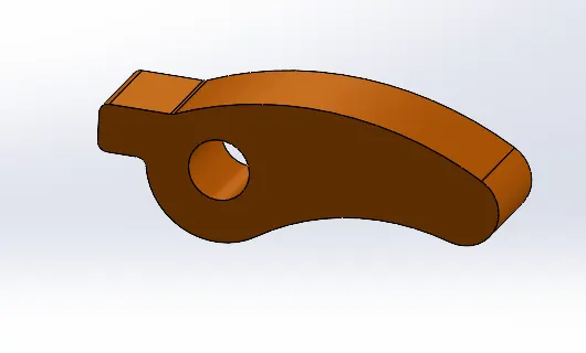
Rocker arm:
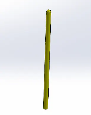
Valve stem:
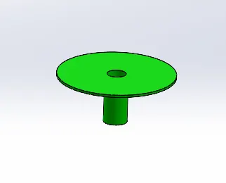
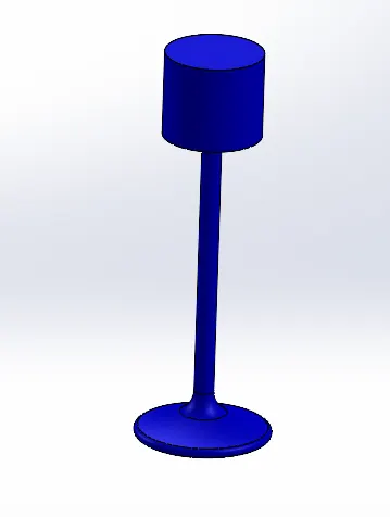
Valve:
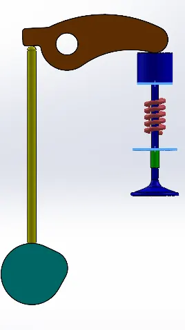
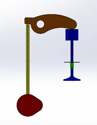
Assembly of IC Engine train:
Case_1 & 2
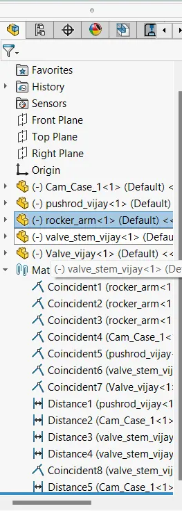
Feature tree of the assembly:
Motion Analysis:
case 1:
- Motor is assigned to cam at the RPM of 1500rpm.
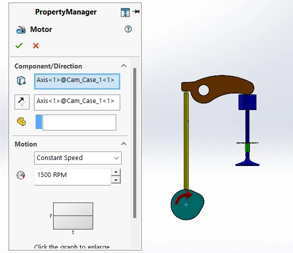
- Contact is assigned between all the components and material (dry steel) is given.
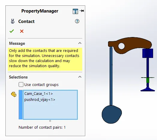
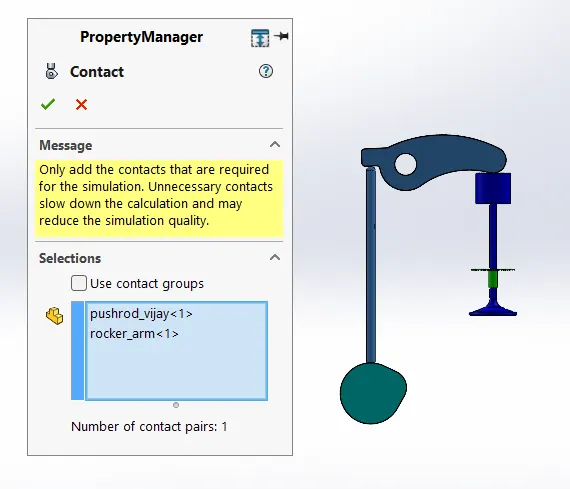
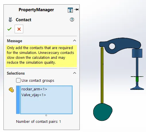
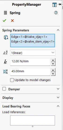
- Apply spring between the top face of the stem and bottom face of valve head and then assign the following values.
- Spring constant: 12 N/mm
- Free Length:45mm
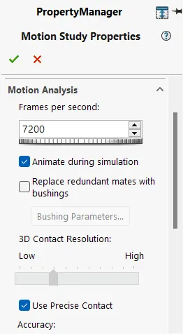
- In motion analysis setting, select precise contact option and 7200 frames per second.
Motion study Results and plots:
CASE_1:
Valve lift:
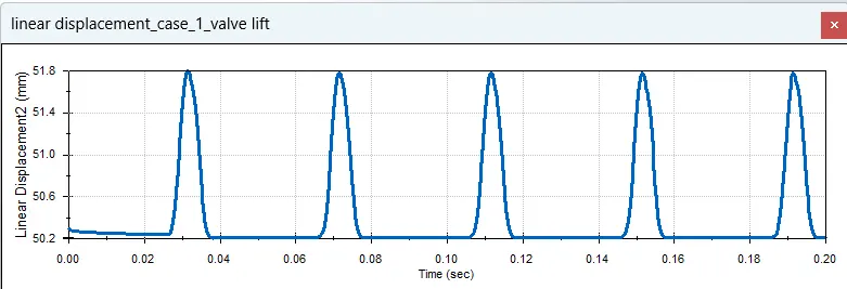
- This plot is for view linear displacement of the value lift with respect to time in sec.
- The minimum value is 50.2 and maximum distance is 51.8 so, total distance travel by the valve is 1.6mm.
- And this cycle happens with the regular period of time repeatedly.
Contact force (Cam and Push rod):
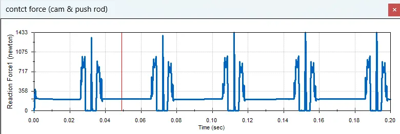
- This plot is for view contact force between the cam and push rod with respect to time in sec. The maximum force attain by the push rod is 1280N.
- And the constantly the 270N force is acted on the cam by the spring reflection force.
- And this cycle happens with the regular period of time repeatedly.
Contact force (Push rod and Rocker arm):
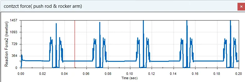
- This plot is for view contact force between the push rod and rocker arm with respect to time in sec.
- The maximum force attain by the rocker arm is 1280N. And the constantly the 280N force is acted on the rocker arm by the spring reflection force.
- And this cycle happens with the regular period of time repeatedly.
Contact force (Rocker arm and valve):
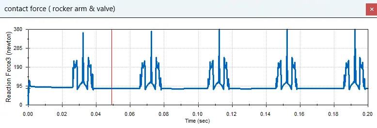
- This plot is for view contact force between the rocker arm and valve with respect to time in sec.
- The maximum force attain by the valve head is 300 N. And the constantly the 90N force is acted on the valve head by the spring reflection force.
- And this cycle happens with the regular period of time repeatedly.
Rocker arm and valve X direction force:
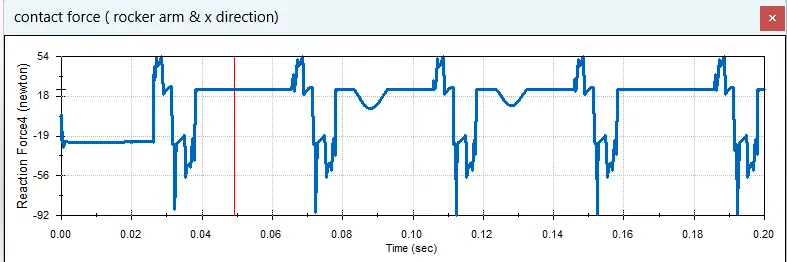
- This plot is for view contact force between the rocker arm and valve in X direction with respect to time in sec.
- The maximum force attain by the valve head is 54N. And the constantly the -92N force is acted on the valve head by the spring reflection force.
- And this cycle happens with the regular period of time repeatedly.
- Here the force is low when compare the previous plot because of the force is splited into two directions namely X and Y direction here we plot the X direction force alone.
case 2:
- Motor is assigned to cam at the RPM of 1500rpm.
- Contact is assigned between all the components and material (dry steel) is given.
- Apply spring between the top face of the stem and bottom face of valve head and then assign the following values.
- Spring constant: 12 N/mm
- Free Length: 45 mm
- In motion analysis setting, select precise contact option and 7200 frames per second.
Motion study Results and plots:
Valve lift:
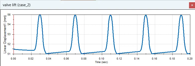
- This plot is for view linear displacement of the value lift with respect to time in sec.
- The minimum value is 51 and maximum distance is 56 so, total distance travel by the valve is 5mm.
- And this cycle happens with the regular period of time repeatedly.
Contact force (Cam and Push rod):
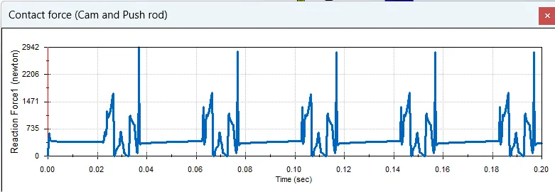
- This plot is for view contact force between the cam and push rod with respect to time in sec.
- The maximum force attain by the push rod is 2800N. And the constantly the 370N force is acted on the cam by the spring reflection force.
- And this cycle happens with the regular period of time repeatedly.
Contact force (Push rod and Rocker arm):
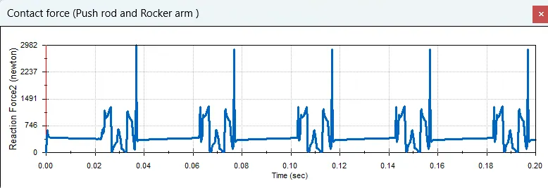
- This plot is for view contact force between the push rod and rocker arm with respect to time in sec.
- The maximum force attained by the rocker arm is 2800N.
- And the constantly the 370N force is acted on the rocker arm by the spring reflection force.
- And this cycle happens with the regular period of time repeatedly.
Contact force (Rocker arm and valve):
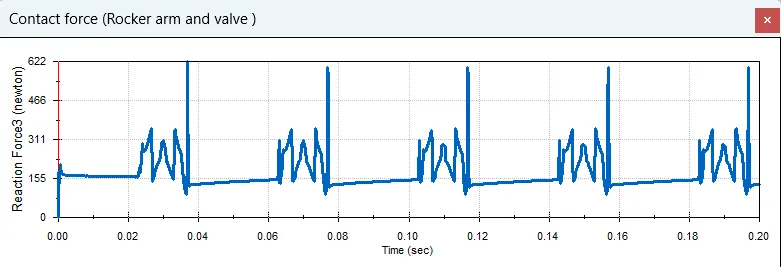
- This plot is for view contact force between the rocker arm and valve with respect to time in sec.
- The maximum force attain by the valve head is 600 N. And the constantly the 130N force is acted on the valve head by the spring reflection force.
- And this cycle happens with the regular period of time repeatedly.
Rocker arm and valve X direction force:
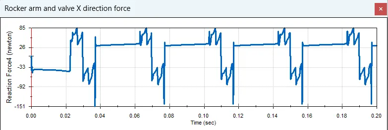
- This plot is for view contact force between the rocker arm and valve in X direction with respect to time in sec.
- The maximum force attained by the valve head is 85 N.
- And the constantly the -140 N force is acted on the valve head by the spring reflection force.
- And this cycle happens with the regular period of time repeatedly.
- Here the force is low when compare the previous plot because of the force is splited into two directions namely X and Y direction here we plot the X direction force alone.
Observation and Result:
- After comparing the two-case study in the first case is has obtained less force (1280N) when compared to the case 2 (2800N).
- It's because the cam length is increased in the case 2 to get smooth flow in the cam follower.
- And the X direction this force is actually two directional.
- so, the common force obtained by the valve is high in both cases.
- But, in the X direction plot the force analysis and plot for force act on the valve in the X direction alone so it is less.
- And the negative force indicate that the rocker arm is moving front and back on the valve head.