MBD Simulation on IC Engine Valve Train
Aim: To design, assemble, perform motion analysis and plot respective graphs for IC Engine Valve Train using Solidworks for the following cases:
| Sl.No | CAM Lift (mm) | Speed (RPM) | Material |
| 1 | 3.5 | 1500 | Cast Carbon Steel |
| 2 | 6 | 1500 |
Cast Carbon Steel |
Components in the Assembly:
CAM: Its has a carefully shaped lobe afixed to a rotating shaft for timly opening and closing of valve.
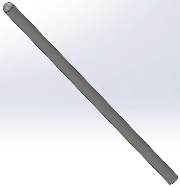
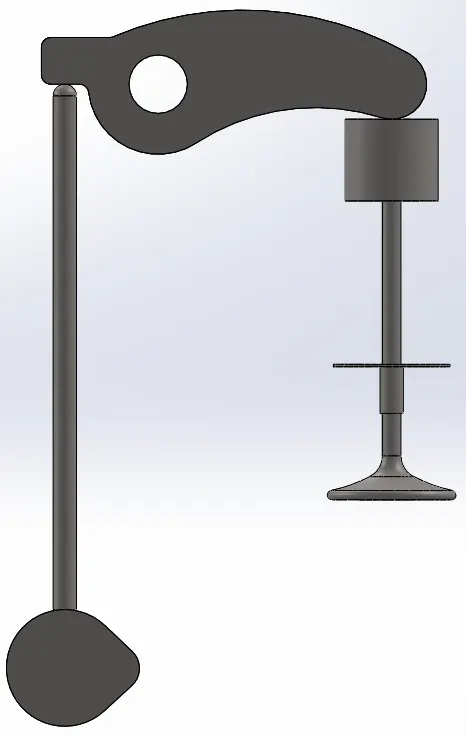
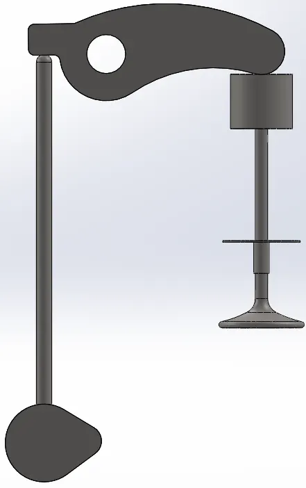
PUSHROD: Its a long rod which helps tranfer of motion from cam to valve through a rocker arm. The bottom end of pushrod gets lifted by the lobe structure on the cam and the top end pushed the rocker arm.
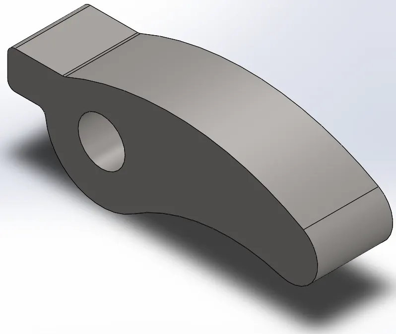
ROCKER ARM: Rocker arm receives actuation from cam through the push and pivots on a shaft to puch the valve for opening.
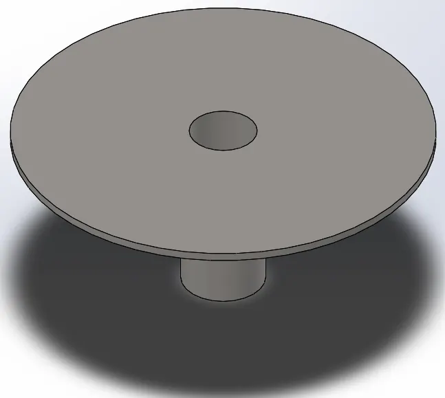
VALVE STEM: Slid into the valve, its helps in holding a spring to rebound and push the valve to closed position.
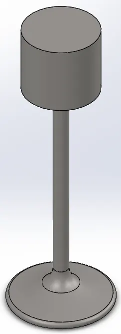
VALVE: Allows and restricts the flow of air/ fuel/ exhaust gases by receiving actuation from a camshaft through timing chain.
Calculations:
CAM Lift = (L-R1)+R2
where,
L = ?; R1 = 12.5mm; R2 = 5mm
Case 1:
3.5 = (L-12.5)+5
L = 11mm
Case 2:
6 = (L-12.5)+5
L = 13.5 mm
Procedure of Design:
1. A 2D sketch for valve is drawn according to the dimensions mentioned in the drawing file and used "revolve" feature to make it a solid body.
2. A 2D sketch for valve stem is drawn according to the dimensions mentioned in the drawing file and "revolve" feature was used to make it a solid body.
3. A 2D sketch for push rod is drawn as per the dimensions mentioned in the drawing file and "revolved" it to make it a solid body.
4. For the rocker arm, a 2d sketch is drawn using features like circle, line, tangent etc and extruded through mid section plane using the dimensions mentioned in the drawing file.
5. According to the conditions mentioned and using cam lift formula, two different cams were sketched and extruded through mid section plane for ease in assmbly of the components.
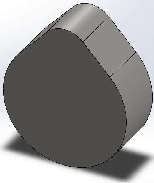
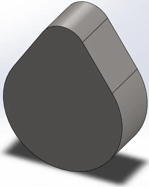
6. Finally, all the components were assembled by providing necessary constraints and performed motion analysis by providing a RPM of 1500 and CAST CARBON STEEL as material to obtain the plots for both the above mentioned cases. Only the cams were replaced while performing motion analysis for those two different cases in the assembly.
Results:
Case 1: CAM Lift of 3.5 mm.
a. Contact force between CAM and Push rod.
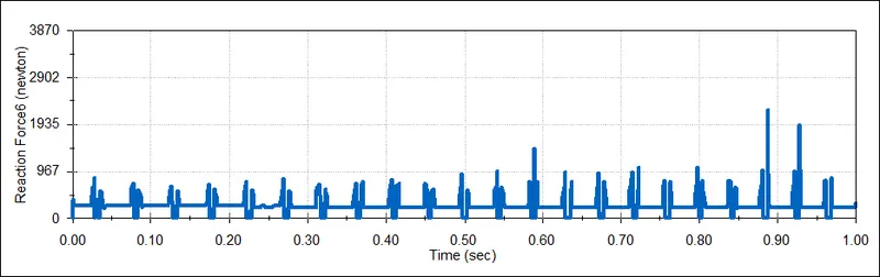
b. Contact force between Push rod and Rocker arm.
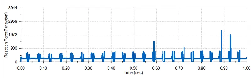
c. Contact force between Rocker arm and Valve.
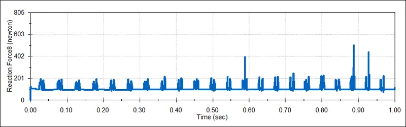
d. Contact force between Rocker arm and Valve about X component.
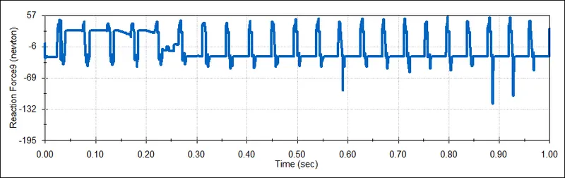
Case 2: CAM Lift of 6 mm.
a. Contact force between CAM and Push rod.
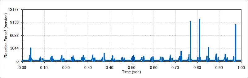
b. Contact force between Push rod and Rocker arm.
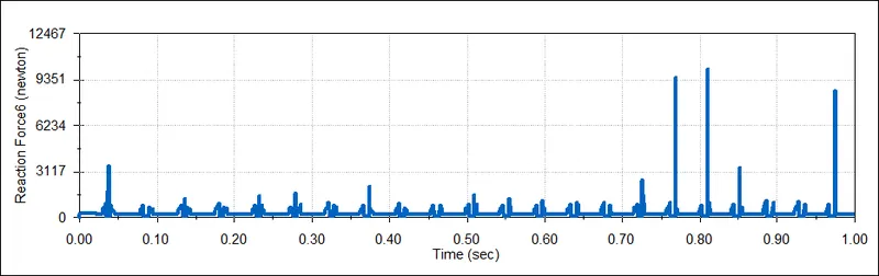
c. Contact force between Rocker arm and Valve.
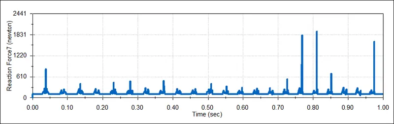
d. Contact force between Rocker arm and Valve about X component.
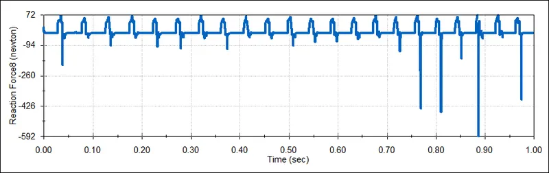
The force values are negative in both the cases when compared with contact force between rocker arm and valve with magnitude and with only x component because the valve slides over the rocker, leading to sliding friction. Also, since values of only one direction is considered, there seems to be a huge difference between the magnitude plot and only x components plot.
Conclusion:
Magnitude of every componets force is incresed as CAM lift value increases.