MBD Simulation on a Piston Assembly
Aim: To model the piston assembly and study the motion analysis for the given three cases.
| Sl.No |
Wrist Pin Offset ` |
Crank Speed (Rpm) |
| 1 | "0" mm | 2000 |
| 2 | 10 mm Positive | 2000 |
| 3 | 10 mm Negative | 2000 |
Components in the Assembly:
Piston Head:
A piston is a component of reciprocating engines, reciprocating pumps, gas compressors, hydraulic cylinders and pneumatic cylinders, among other similar mechanisms. It is the moving component that is contained by a cylinder and is made gas-tight by piston rings.
Wrist pin:
It is used to connect the piston head and connecting rod allowing possible rotation through it.
Connecting rod:
It connects the piston and the crank shaft of the assembly allowing the linear motion of the piston to transfer into useful rotational motion in the crank.
End cap:
End cap acts as a joint between the crankshaft and the connecting allowing possible rotational motion through it.
Crank:
It is the rotational part of the piston assembly which gets rotated due to linear motion of the piston head.
Procedure of design:
1. A 2D sketch for the piston is drawn with the dimension given in the drawing file and is made into a solid body using "revolve" function. Another sketch is drawn on the front plane and "revolved cut" and "Linear pattern" functions are used to create grooves for piston rings. A circular through hole is made to create a compartment for wrist pin setup along with a cut section made using 3 point arc to make semicircular kind of cut at the bottom of the piston.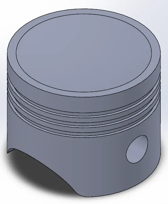
2. For connecting rod, a 2d sektch is made according to the dimensions given in the drawing file and extruded through mid section plane about 30mm. Two circular through hole cylindrical structures are made at the bottom of the rod to fit in the end cap later. Desired edges are chamfered by 2.7mm.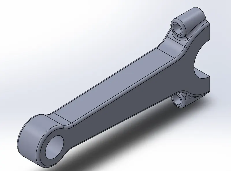
3. Sketch for the end cap is made according to the dimensions given in the drawing file and mid section plane is used while extruding the sketch about 30mm. Similar throughhole cylindrical structures are made to fit in the connecting rod.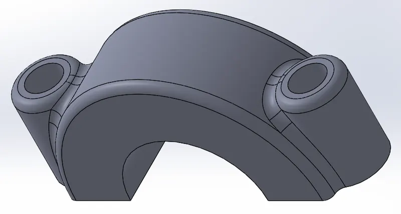
4. A through cylinder with chamfered end is made for wrist pin according to the dimensions mentioned in the drawing file.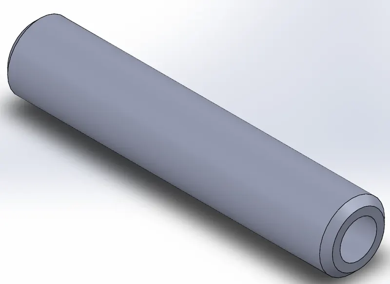
5. For the crank, sketch was made according to the dimensions in the drawing file and the feature was mirrored to avoid making the part twice.
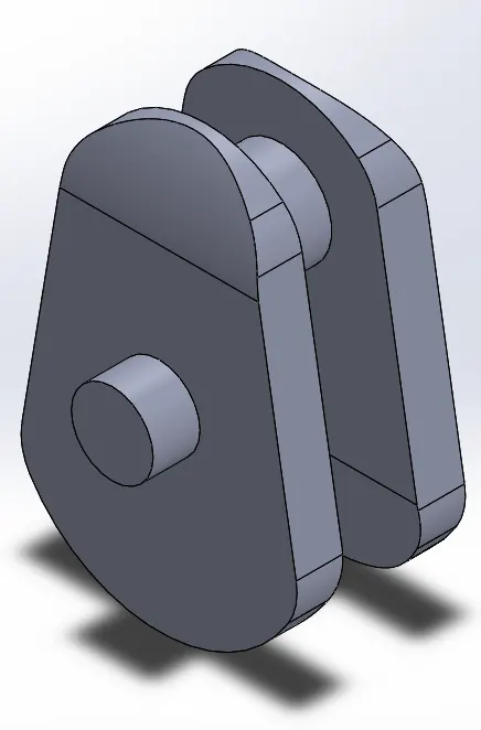
6. Finally, all the components are assembled using the constraints like coincident and offset distance to achieve the desired assembly.
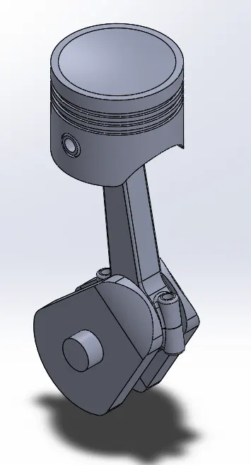
Case 1: "0"mm offset
Motion analysis was performed as usual by setting the motor with a RPM of 2000 on the crankshaft and assign the contacts with material "steel(dry)". gravity was also assigned towards "Y" direction and linear displacement graph was plotted.
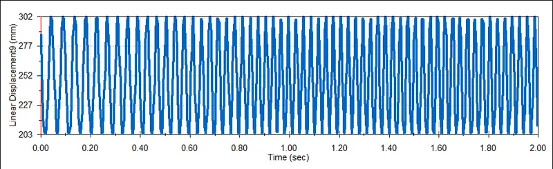
Case 2: 10mm positive offset
Additional contraints for coincidence between the piston and crankshaft is given through ditance offset of 10mm to study the motion analysis of this condition.
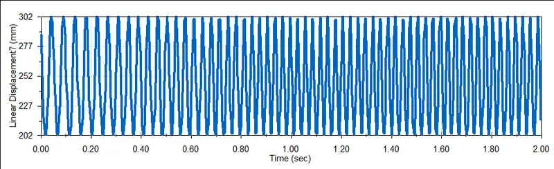
Case 3: 10mm negative offset
Very much similar to case 2 just added another constraint to distance offset by checking the box that say "flip dimensions" to study the negative offset motion analysis.
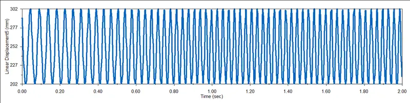
Conclusion:
The superimposed plot is as follows:-
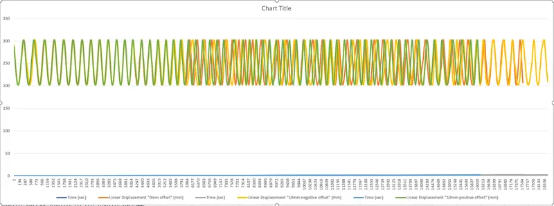
There seems to be very slight difference between all the three cases and offset is provided to reduce the power loss and wear.
Please refer to the attachment below for solidworks part and assembly files.