Week 1 Stress Concentration on a Plate with hole
Aim: To design two plates with different holes and determine the total deformation and maximum stress for each case. Also, as a product engineer's point of view,
- Compare the deformation and maximum stress developed
- Find out best design from analysis standpoint.
- Find out best design from manufacturing standpoint.
Procedure:
- Open Ansys workbench and click on static structural.
- Right click on geometry and select edit geometry in spaceclaim. The default material in enginnering data is structural steel so no changes were made.
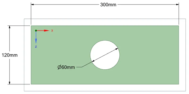
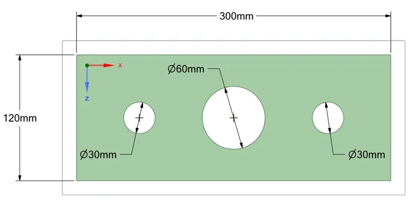
- Make a 2-D sketch for each case as given in the question and use pull command to extrude it into a solid body of thickness as mentioned.
- Right click on model and select update to import the geometry from spaceclaim.
- Once its processed, right click on model once again and select edit.
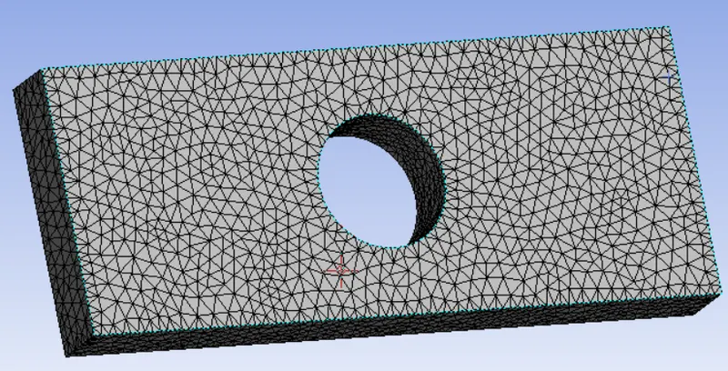
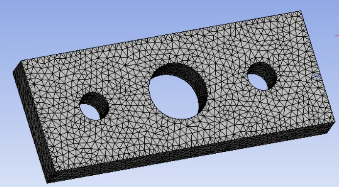
- Select on mesh and change the element size. 3.5mm is used here due to nodes restriction in academic version of Ansys. Also, change the method from automatic to tetrahedron for tetrahedral structure of mesh.
- Right click on static structural -> Insert -> Fixed support and select left face of the plate to make it fixed. Once again, right click on static structural -> Insert -> Force and select the right face of plate so that the force acts in the opposite direction of fixed support.
- Change the "define by" from vector to component and input a load of -500N in the X component (or the component where the support is fixed and force is applied). The negative value indicates force applied in the direction opposite to face of fixed support (tensile force).
- Select solve and wait till its processed. Right click on solution -> Insert and select deformation and stress. Then select evaluate.
- Finally, select total deformation or equivalent stress to view the resulting characteristics.
Results:
| Title | Case 1 | Case 2 |
| Geometry |
Thickness = 30mm |
Thickness = 30mm Space between the circular holes = 90mm |
| Mesh |
Element size = 3.5mm |
Element size = 3.5mm |
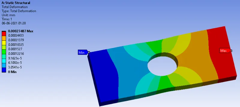
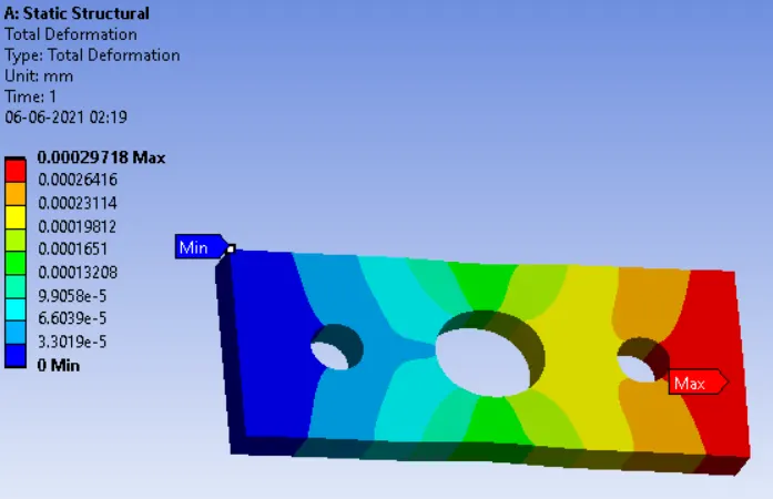
| Total Deformation |
Deformation = 0.00027487 mm |
Deformation = 0.00029718 mm |
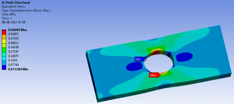
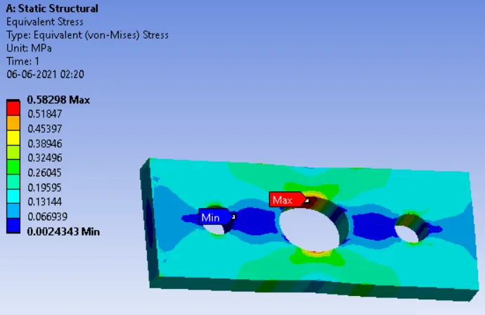
| Max stress |
Max stress = 0.60669 MPa |
Max stress = 0.58298 MPa |
Conclusion:
- The case 2 design seems to deform little bit higher than case 1 design. But the maximum stress experienced by case2 design is lower than case 1 due to uniform distribution of stress through 2 extra holes is case 2 design.
- From the analysis point of view, case 2 design is preffered due to lower maximum stress value compared to that of case 1 design, thanks to the two extra holes which uniformly distributes the stress concentration through the plate. Deformation wise, ofcourse case 2 design deformed more than case 1 design but the value is very small and close to negligible. Thus, case 2 design is preferred here.
- From manufacturing point of view, the case 2 designs takes more time to be manufactured compared to case 1 due extra holes that needs to be cut on the plate. If the characteristics of case 1 design meets the requirements, then it is preferred in terms of manufacturing standpoint.