MBD Simulation on a Piston Assembly
AIM :-
To conduct motion study of piston assembly and to plot the linear displacement of the piston head from three conditions where the wrist pin positions change.
SOLIDWORKS MODELS :-
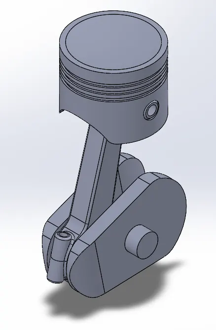
The assembly consists of the following parts,
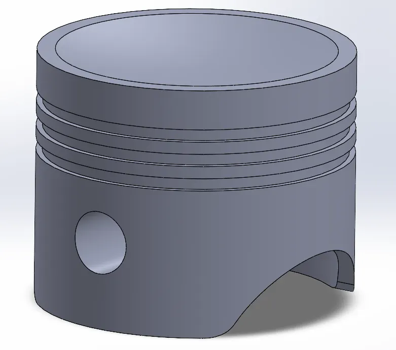
- Piston.
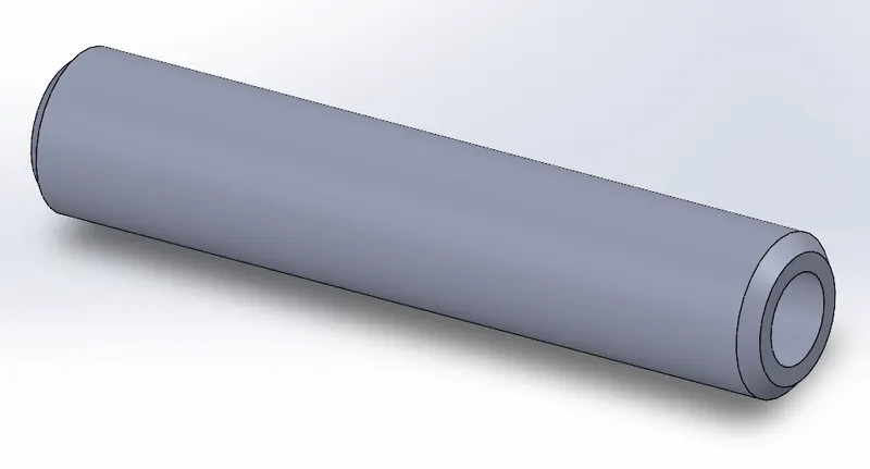
- Wrist pin.
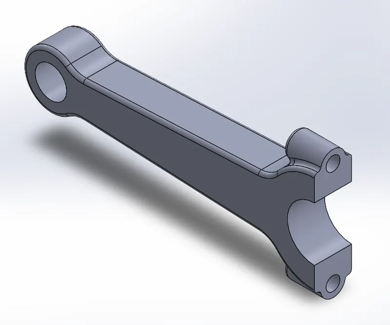
- Connecting rod.
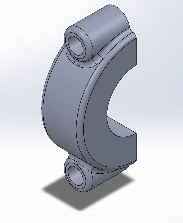
- End cap.
- Crank.
1. Piston Model,
2. Wrist Pin Model,
3. Connecting Rod Model,
4. End Cap Model,
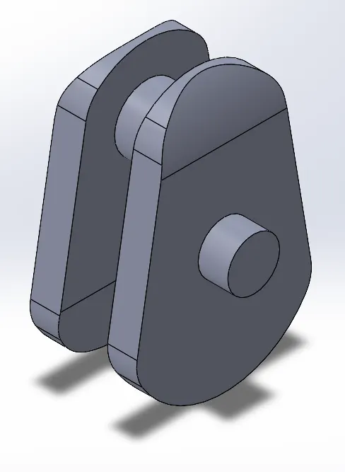
5. Crank Model,
Assembled Model,
OUTPUT :-
- No wrist pin offset.
- 10 mm positive wrist pin offset.
- 10 mm negatie wrist pin offset.
1. No Wrist Pin Offset,
The slot for the wrist pin on the piston is modelled without an offset where the center axis of the wrist pin and the crank are aligned.
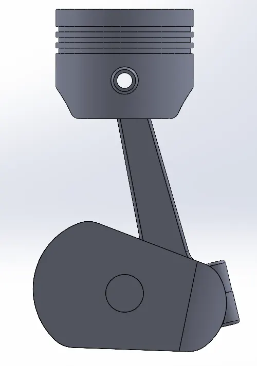
The motion analysis is conducted where the motor input is provided to the crank and a speed of 2000 rpm is set. All the components are selected for mechanical contact and the material is changed to steel (dry). A gravitational component is added in the Y direction to indicate that the gravity acts downwards during the simulation. The frame rate is set to 100 fps to get a more precise calculation and a better plot. The motion study is calculated and the linear displacement of the piston is plotted as shown below.
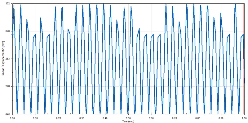
The plot shows the displacement of the piston as it moves from the top dead center (TDC) to bottom dead center (BDC). The highest displacement being 302 mm and the lowest being 203 mm. From this the stroke length can be calculated which is 99 mm. The plot is not smooth and variations are observed with the highest point in certain time steps. This is due to a low frame rate used and the calculation is done only for a second. Such a measure was taken due to the time constraint. In order to get a much more smoother plot the frame rate must be set at 7200 fps, but this would take time for the simulation to run and calculate.
2. Positive Wrist Pin Offset,
When viewed from the front, if the crank's rotation is in the clockwise direction, then the positive offset of the wrist pin is to the right of the piston axis. This change is made by removing the vertical constraint between the center of the plane and the wrist pin slot center on the piston. The slot is then shifted to the right and the distance between the slot center and the front plane center is defined as 10 mm using the smart dimension feature.
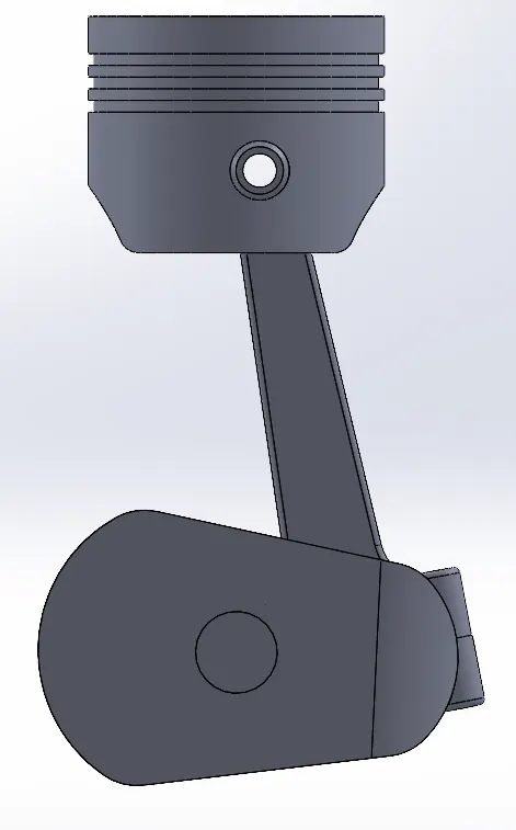
For the motion analysis, motor input is provided to the crank at 2000 rpm. All parts are selected for mechanical contact and gravity is selected to act in the y direction. The frame rate is set to 100 fps. The linear displacement of the piston is plotted as shown below.
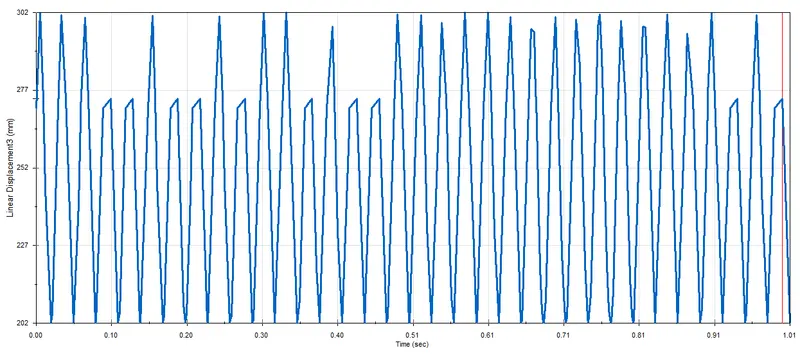
The plot shown is the movement of the piston from TDC to BDC. The highest displcement is 302 mm and the lowest displacement is 202 mm, which indicates that the stroke length is 100 mm which is 1 mm more than when there was no offset for the wrist pin. The variation in the plot is due to a low frame rate.
3. Negative Wrist Pin Offset,
When viewed from the front, if the crank's rotation is in the clockwise direction, then the negative offset of the wrist pin is to the left of the piston axis. This change is made by removing the vertical constraint between the center of the plane and the wrist pin slot center on the piston. The slot is then shifted to the left and the distance between the slot center and the front plane center is defined as 10 mm using the smart dimension feature.
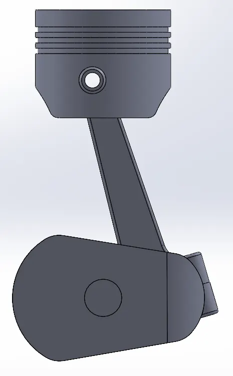
For the motion analysis, motor input is provided to the crank at 2000 rpm. All parts are selected for mechanical contact and gravity is selected to act in the y direction. The frame rate is set to 100 fps. The linear displacement of the piston is plotted as shown below.
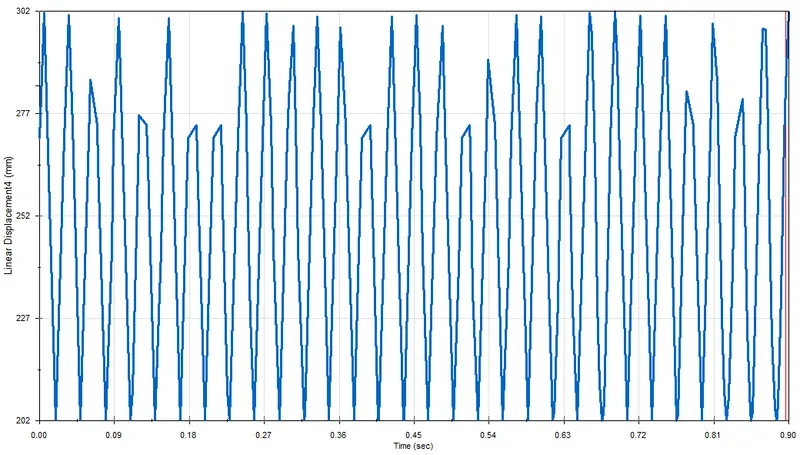
Here too the plot shown is the movement of the piston from TDC to BDC. The highest displcement is 302 mm and the lowest displacement is 202 mm, which indicates that the stroke length is 100 mm which is 1 mm more than when there was no offset for the wrist pin. The variation in the plot is due to a low frame rate.
CONCLUSION :-
An assembly to study the kinematics of a piston is created and motion study is performed to analyse the linear displacement of the piston based on the position of the wrist pin.