Introduction to REVIT concepts
Q1)
AIM :
From the file menu, create a new project (Structural / Architectural / Construction template ) and name the project appropriately
PROCEDURE :
1)open the revit , after opening we get an interface as shown below.
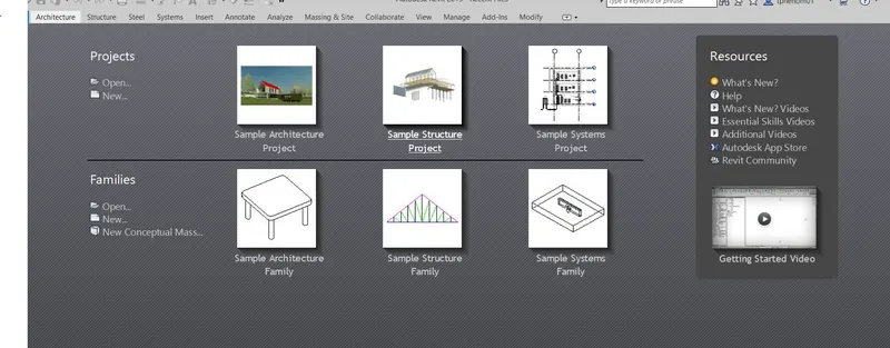
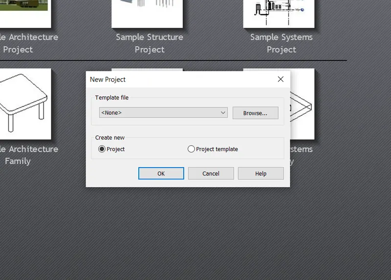
2)there is an option new on the interface ,after clicking we get an interface as shown below.
3)select the option for architectural template and press ok.
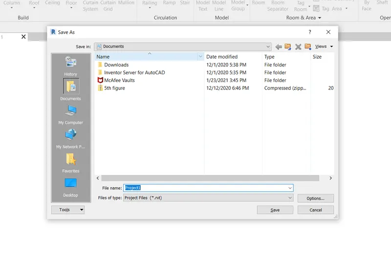
4)then we enter the main interface of revit and there is an option on the left top side called save.
5)click on it, and enter the name,project file will be saved as shown below.
Q2)
AIM :
Save the new project file. Close and open using icons from file toolbar.
PROCEDURE :
1)open the revit , after opening we get an interface as shown below.
2) select the option for new and open a new sheet, here opening task is completed.
3)in order to close the project file, just go to file option at the left top of interface.
4) click on it, and at last there is an option called close.
5) click on it and the file will be closed.
Q3)
AIM :
From the architecture/ structure toolbar familiarize with options to draw a wall. Create a rectangular layout of walls of about 40’-0” X 35’-0”.
PROCEDURE :
open the revit select the new file and save the project file.
on the interface we find an option called wall.
click on it and a wall can be drawn ,drag it in the direction you want.
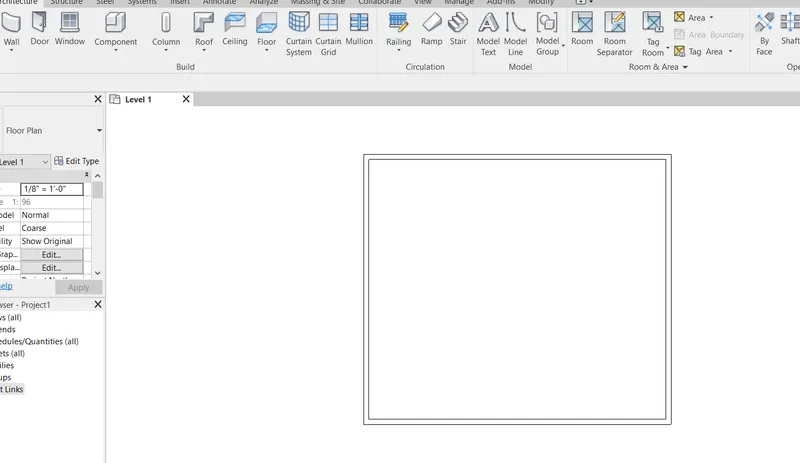
draw a horizontal line of 40' followed by a vertical wall of 35'.
in this way a wall of 40'*35' is obtained as shown in figure.
Q4)
AIM :
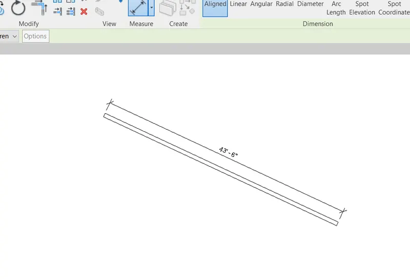
From the Annotate toolbar use the aligned option to add dimensions to the layout.
PROCEDURE :
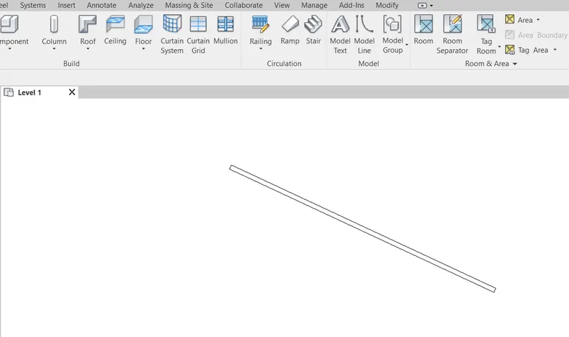
open the revit and go to the wall option at the left top corner.
select it and draw an inclined line.
now go to the aligned dimension and select the two corner points of the line.
and drag it in its direction, a wall with its aligned dimension is obtained as shown in figure.
Q5)
AIM :
switch to different wall types using properties browser.
PROCEDURE :
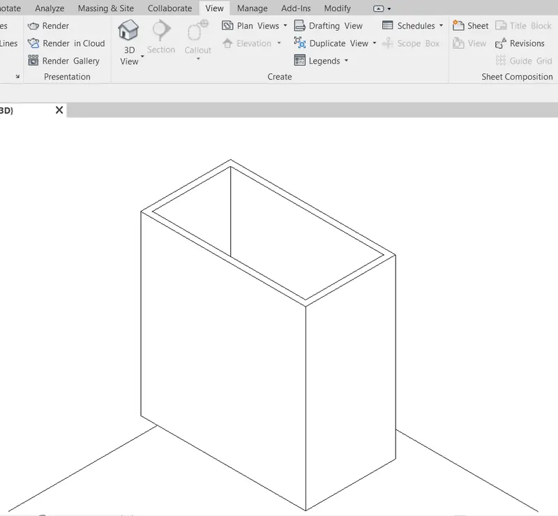
1) make a 3d wall as shown in previous figures.
2)select the properties option from the ribbon.
3)select the type of wall we want.
Q6)
AIM :
Create a 3D view from the view toolbar and save the view with the appropriate name.
PROCEDURE :
1)open the revit software and draw a wall with the help of wall command as shown in figure.
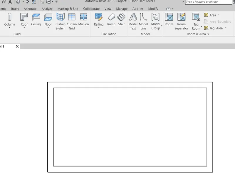
2)after drawing the wall ,go to the view option from the tool bar and click the 3d view option ,view will be converted
to 3d as shown in figure.
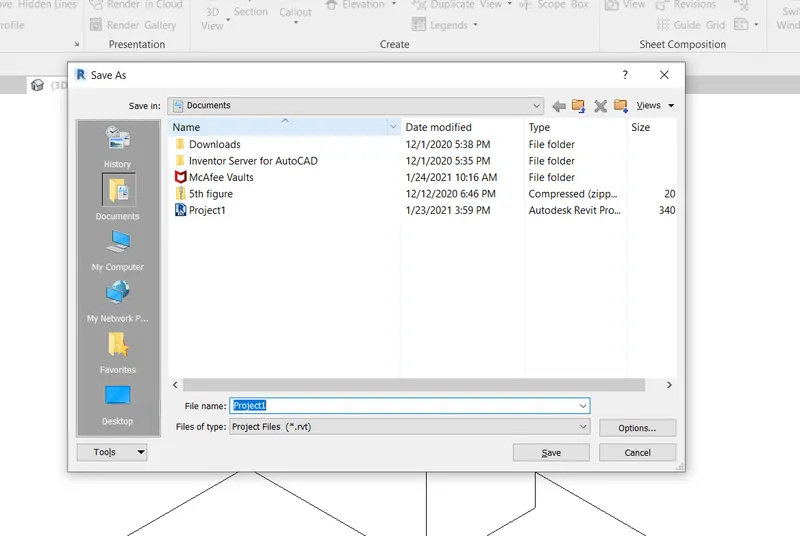
3)to save the file, just go to the file option and click save option and put the name as shown in figure,
fill will be saved.
Q7)
AIM :
navigate through the 3d model using viewcube.
PROCEDURE :
1) open the revit and draw a cube as shown in the previous figures.
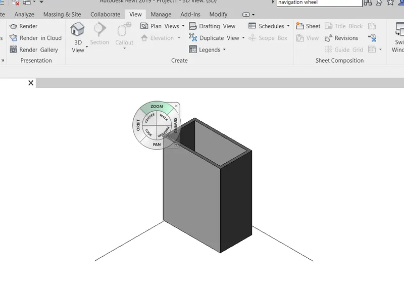
2) go to the navigation bar at the right side of screen.
3) click on it and rotate it in any direction you want.
4)select the pan option to view it in the direction we want.
Q8)
AIM:
Use the visibility settings option below to switch model to shaded, realistic, hidden lines options.
PROCEDURE :
1)open the revit software and draw a wall with the help of wall command as shown in figure.
2) change the view to 3d and from the tool bar ,a view as shown below will be obtained.
3)at the bottom of the screen there is an option called visual styles.
4)select this option and there are different visual styles available in it such as realistic,shaded.
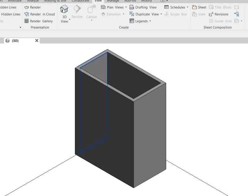
5)change the view to shaded and figure will be shaded as shown below.
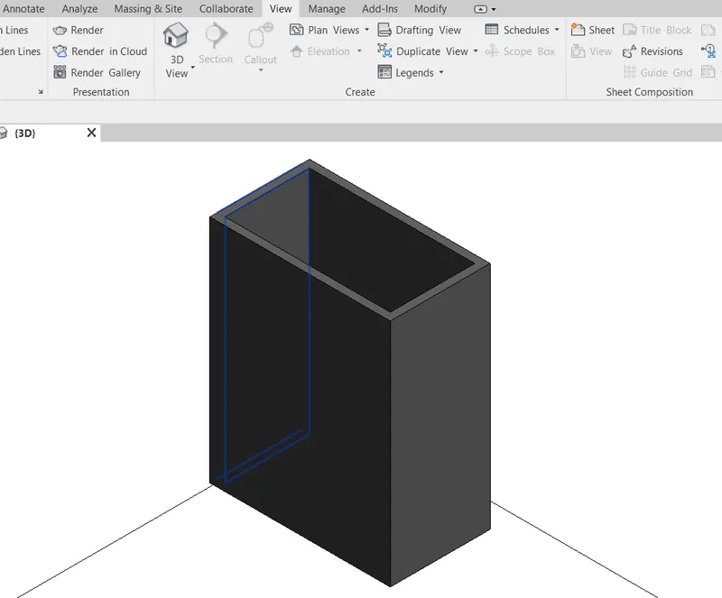
6)change the view to realistic, realistic figure will be obtained.
Q9)
AIM :
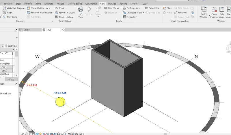
Turn the sun path on and off to view shadings in the layout created.
PROCEDURE:
1)open the revit software and draw a wall with the help of wall command as shown in figure.
2) change the view to 3d and from the tool bar ,a view as shown below will be obtained.
3)with the help of visual styles, shade the figure turning off the sunpath there will be no
change in the figure as shown below.
4)turning on the sunpath figure will be changed as shown below.
Q10)
AIM :
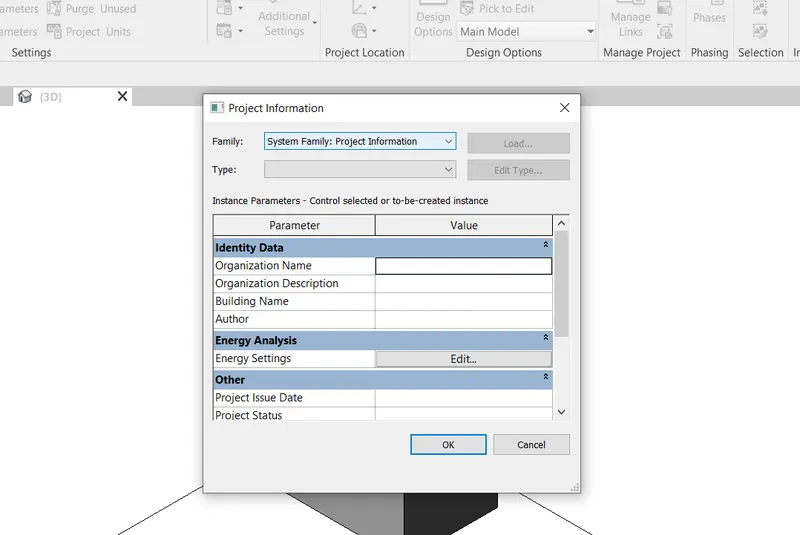
Use the Manage toolbar to enter project settings, project name, and project issue date (choose according to your convenience).
PROCEDURE :
1)open the revit software and draw a wall with the help of wall command.
2)to enter the project settings go to the manage tool bar ,after selecting it
we get an option at the left top side called project informaion.
3)after clicking project information a dialogue box will appear as shown in figure.
4)in this dialogue box there are different options available ,which can be filled as per the convenience
of owner.
Q11) What is the Analyze toolbar used in Revit? How it is beneficial for design and modeling.
ans)analyse tool bar is the tool which helps to combine the different loads in the structure , load combinations, boundary
conditions etc. it is used to analyse the structure with all the different loads applied in the object which gives
the analysis report as the result. it helps to detect the load failure in structure.
Q12)what are the links that revit supports to be linked to the model?
ans) links that revit supports are
1)link revit
2)link ifc
3)link topography
4)link cad
Q13)why do you need collaborate tab in revit ?how it supports modelling and its efficiency.
ans)collaborate in revit is cloud based service which allows any revit user inside or outside
the network to collaborate on the revit model. many users can work under the same plan
or drawing which makes the work more efficient and the productivity is more as many people
can work under one project and time is reduced in completing the project.