Introduction to REVIT concepts
Aim 1:
From the file menu, create a new project (Structural / Architectural / Construction template ) and name the project appropriately
Introduction:
Open the Revit software and create the new project in it and name the project by saving it in the system.
Procedure:
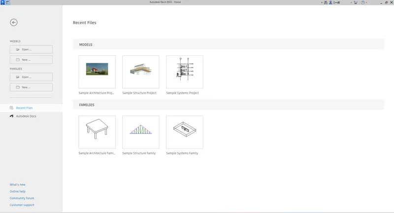
- Open Revit Software.
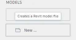
- Click on the New in Model tab to create the New project in Revit.
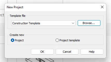
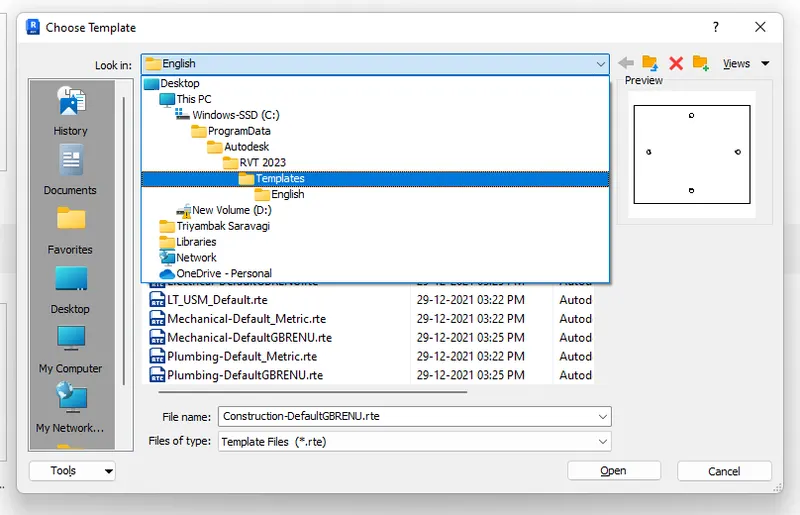
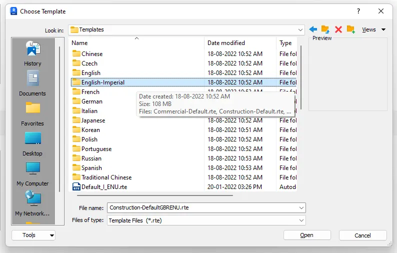
- Click on Browse option in the Pop-up.
- Go to templates in the drop down list.
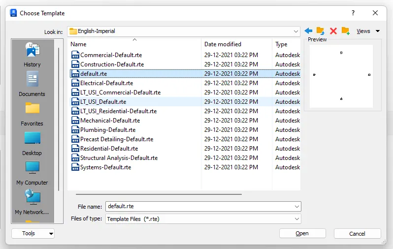
- Select English-Imperial.
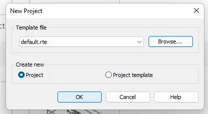
- Select Default template.
- Click on OK.
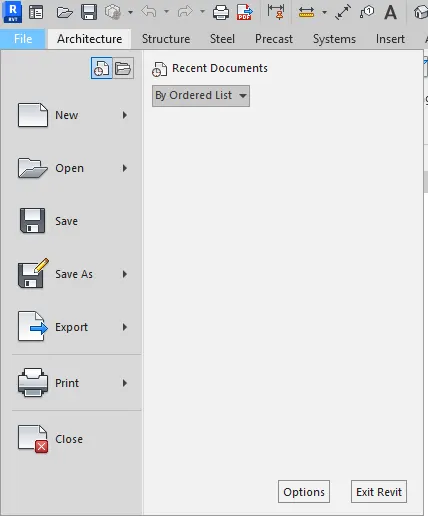
- Clicl on File tab on the top left corner.
- Click on the Save Button in the File drop down list.
- Select the destination of the file to save it and name the file as per the choice.
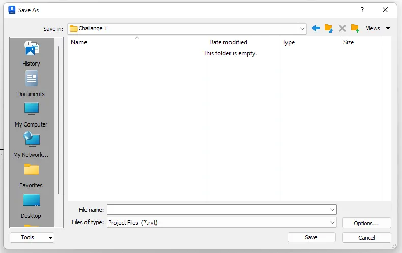
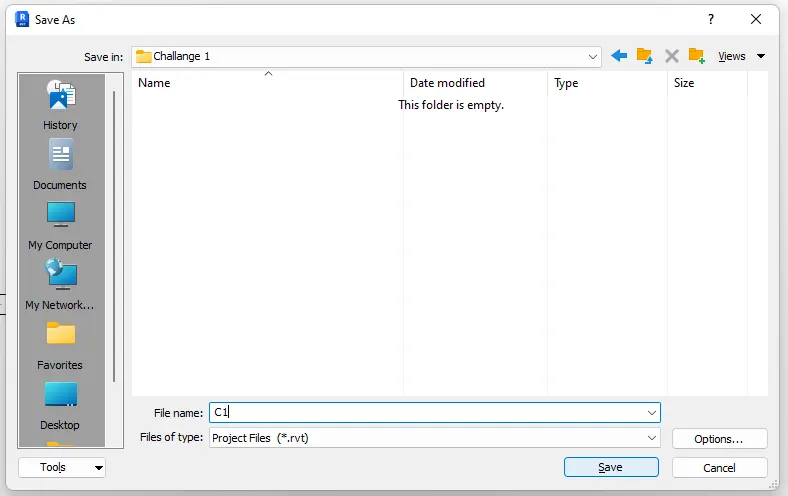
Final Result:

Aim 2:
Save the new project file. Close and open using icons from file toolbar.
Introduction:
Save the file again using save as option and close the file ang again open the file from the thumbnail view in the Revit open screen.
Procedure:
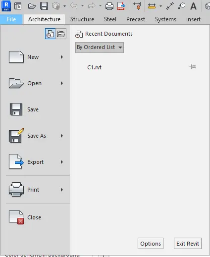
- Click on the File tab on the top left corner.
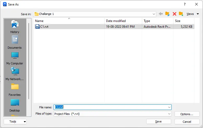
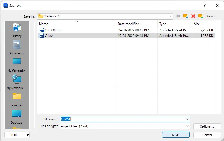
- Now select the save as option in the file drop down.
- Now Select the project option in the save as list.
- Click on the save button.
- Now again open the file tab drop down.
- Select the Close in drop down menu.
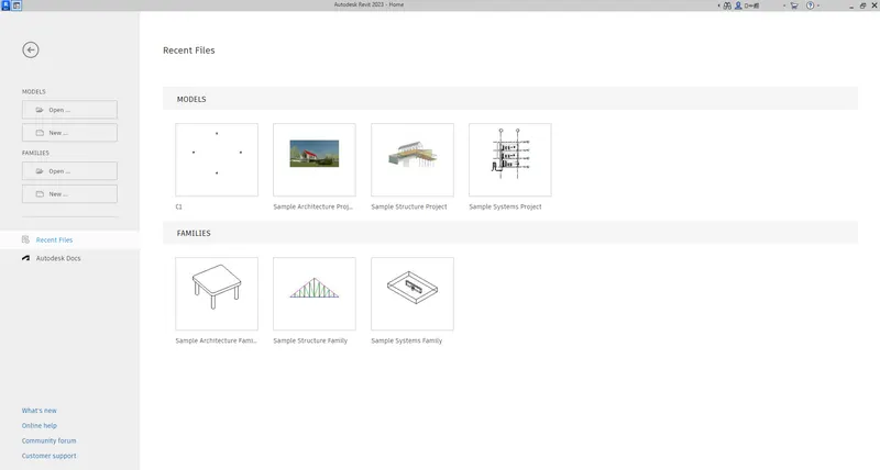
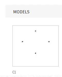
- Now select the project file in the Model Thumbnail.
- file will get open.
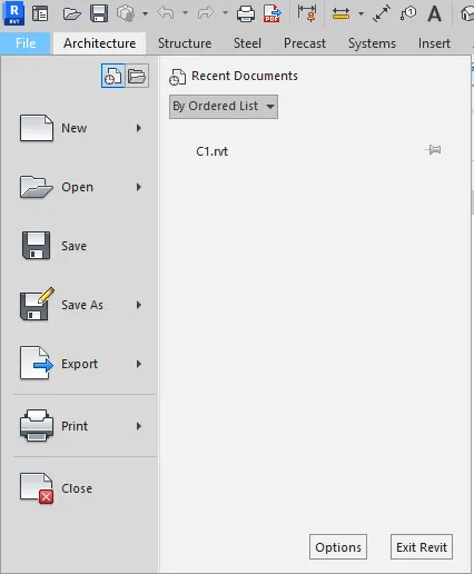
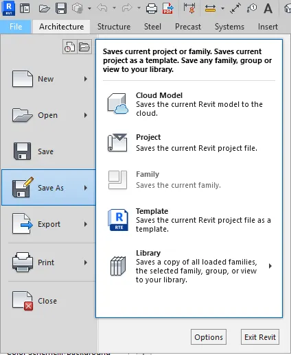
Final Result:
The File saved successfully and closed again it get correctly open.
Aim 3:
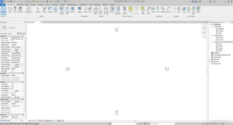
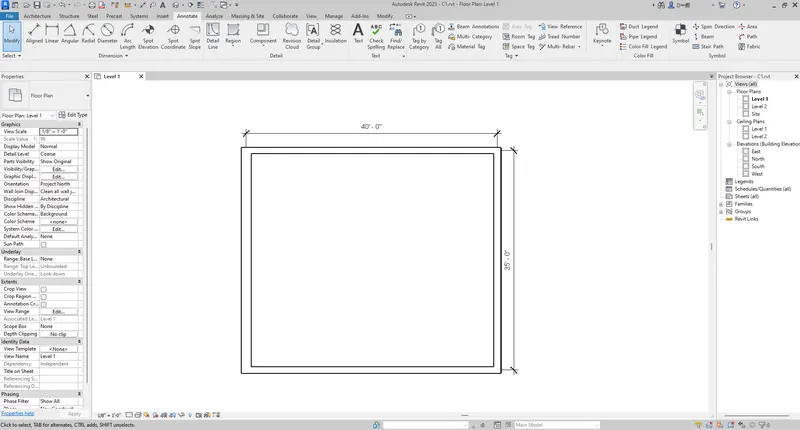
From the architecture/ structure toolbar familiarize with options to draw a wall. Create a rectangular layout of walls of about 40’-0” X 35’-0”
Introduction:
Open the architecture tab in toolbar and with the help of the wall tool draw the rectangular layout of the wall of the 40'-0" x 35'-0".
Procedure:
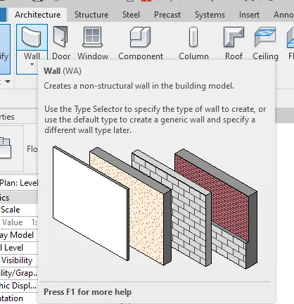
- Select the wall tool in the Architectural tab in the toolbar.
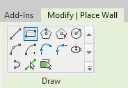
- Select the rectangle profile in the modify: wall tab
- Draw the rectangle in the work-plane.
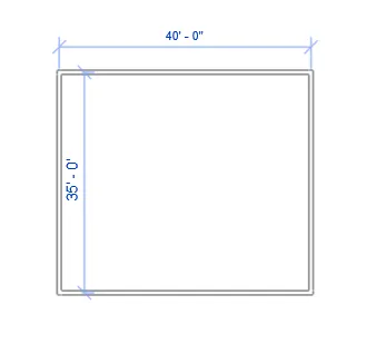
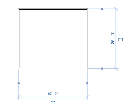
final Result:
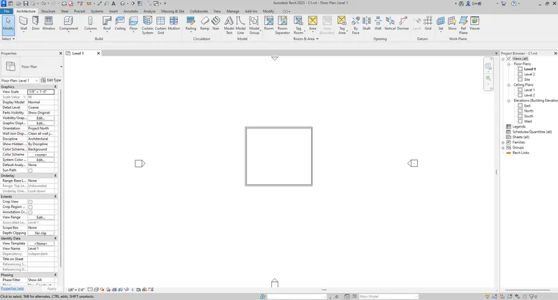
Aim 4:
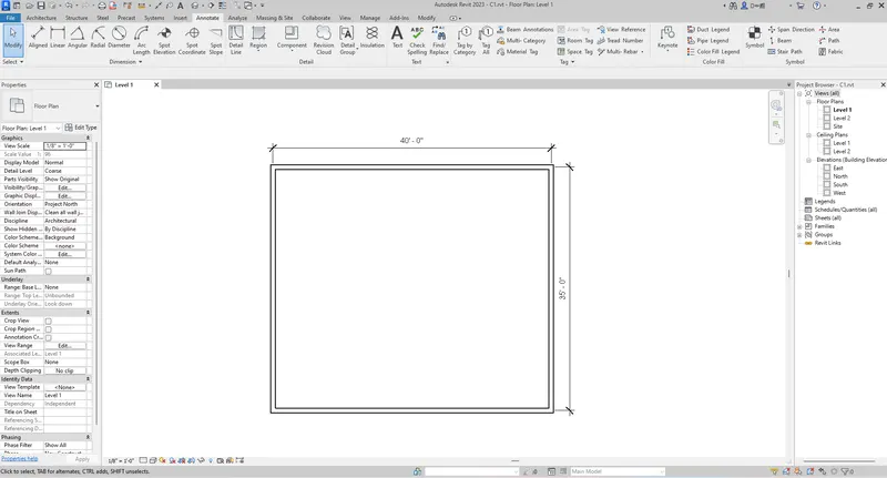
From the Annotate toolbar use the aligned option to add dimensions to the layout.
Introduction:
Dimensioning the layout using Align tool in the Annotate tab in the toolbar.
Procedure:
- Go to Annotate tab in the Toolbar.
- Select the Aligned tool in the Dimension tab of the Annotate tab.
- Annotate the dimension of the layout in the work-plane.

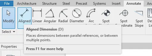
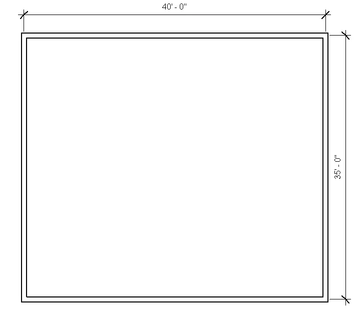
Final Result:
Aim 5:
Use the properties browser to switch to different wall types
Introduction:
- With the help of the property Panel change the type of the wall.
Procedure:
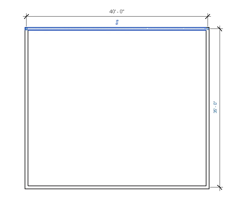
- Select any of the wall from the rectangle layout.
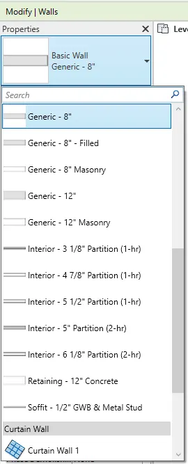
- Select the drop down of the Property Panel in the Left Side of the UI.
- The selected wall type is Generic - 8", Now Change it to another type Select any other type from the drop down.
- Similarly Change the other three wall type.
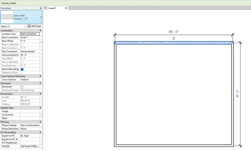
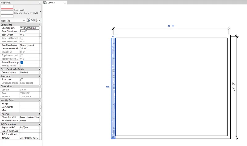
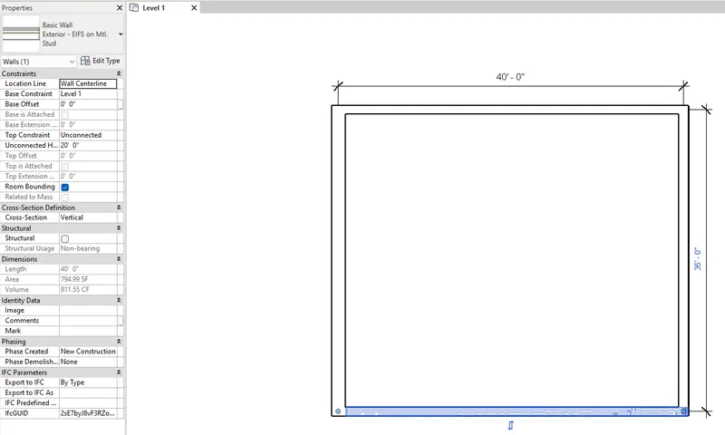
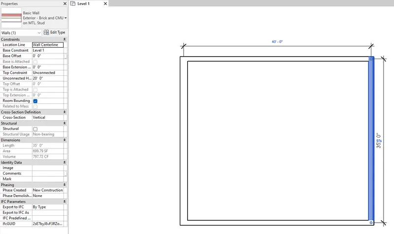
Final Result:
Aim 6:
Create a 3D view from the view toolbar and save the view with the appropriate name.
Introduction:
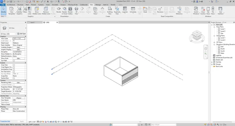
with the 3D tool open the 3D view of the wall layout and save the view with the appropriate name.
Procedure:
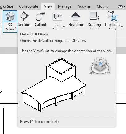
- Open View tab in the toolbar.
- Select the 3D View tool in the Create tab.
- 3D View work-plane will be open in the project.
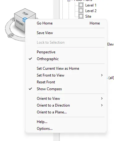
- Right click the view in the view-cube.
- Select the Save View option in the right click drop down.
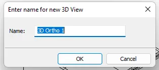
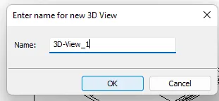
- Name it as 3D-View_1 and select the OK button.

Final Result:
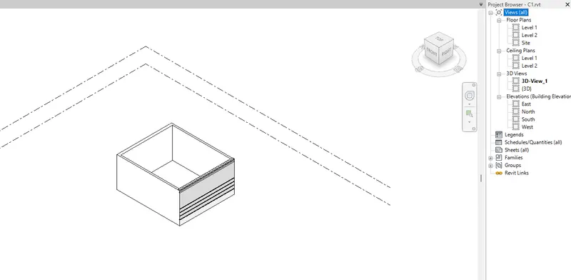
View has been saved under the 3D section of the project browser panel.
Aim 7:
Navigate through the 3D model using the view cube. Orbit/pan through the model layout created
Introduction:
With the help of the navigation tool orbit or pan the view in 3D work-plane.
Procedure:
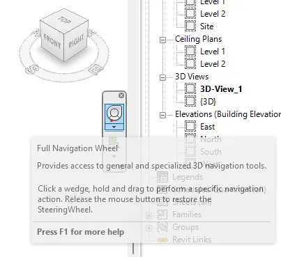
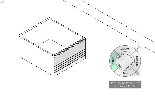
- Select the Full Navigation wheel.
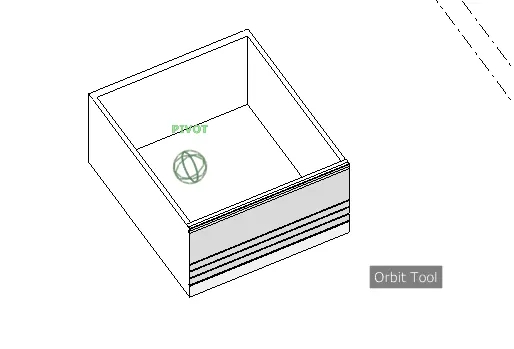
- Press and hold the left click on Orbit in the Navigation Wheel.
- Now Orbit the View.
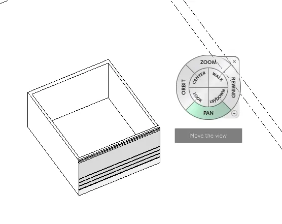
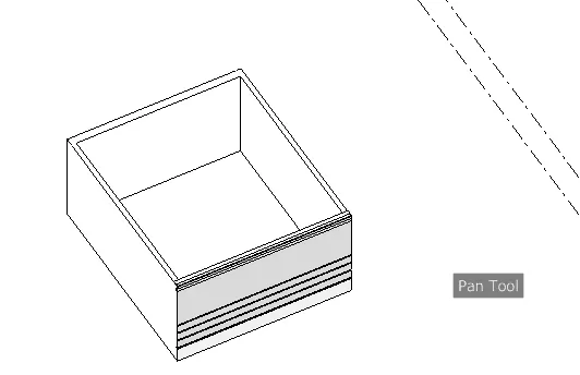
- Now press and hold the left click on the pan.
- Now try pan in the view.
Final Result:
With the help of the Navigation Wheel we can faster and easily navigate the view and layout of the project.
Aim 8:
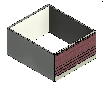
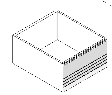
Use the visibility settings option below to switch model to shaded, realistic, hidden lines options.
Introduction:
Check the different visibility view of the layout in 3D.
Procedure:
- Select the Visual style from the view menu bar at the bottom of the workspace.
- Select the Shaded in the List.
- Select Realistic in the list.
- Now Select the Hidden Lines in the list.

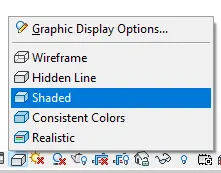
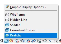
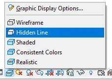
final Result:
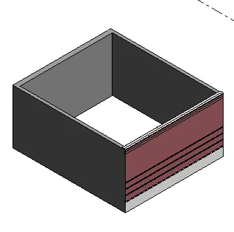
Aim 9:
Turn the sun path on and off to view shadings in the layout created.
Introduction:
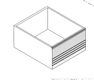
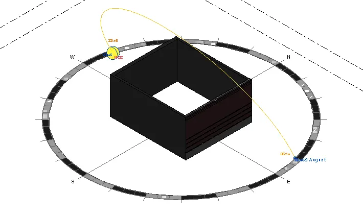
Make the Sun path on and see the sun path and shades of the wall drawn.
Procedure:
- Initially the Sun path is off.
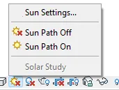
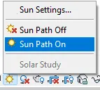
- Left click the Sun path in the view bar.
- Select the Sun Path ON.
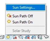
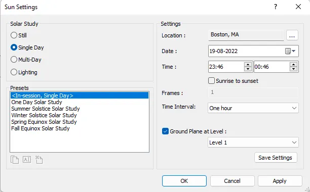
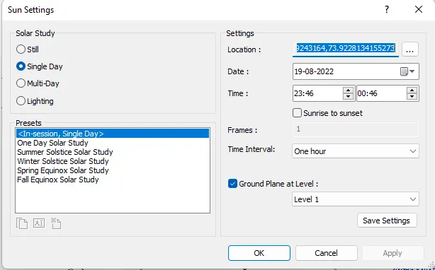
- Select the Sun Settings in the Sun Path list.
- Select the Single Day in the dialogue box.
- Select the location in the Settings.
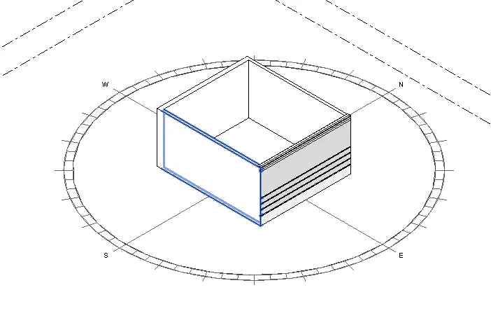
- Now see the Sun path in the view.

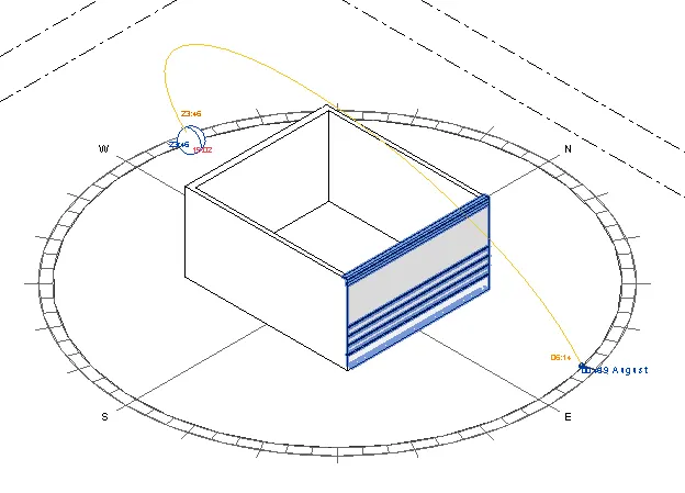
Final Result:
Aim 10:
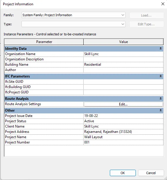
Use the Manage toolbar to enter project settings, project name, and project issue date (choose according to your convenience).
Introduction:
Enter the Project Details like settings, name, issue date of the project.
Procedure:
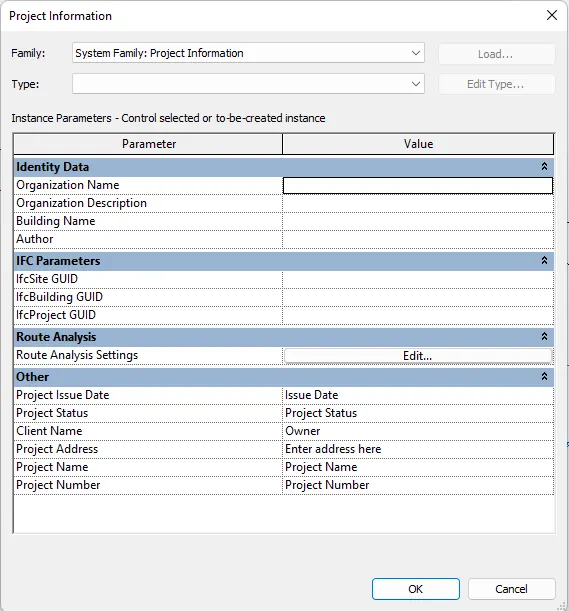
- Open the Manage tab in the toolbar.
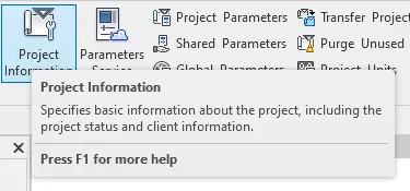
- Select the Project Information tool in it,.
- Edit the Details in the list of the project Information box.

final Result:
Aim 11:
What is the Analyze toolbar used in Revit? How it is beneficial for design and modeling
Solution:
Analyze tab has various tools to analyze the building without any errors to occurred while designing the structure.
It Consists of :
- Structural Analytical Model: It has tools to apply the realistic load, boundary condition, members, panels etc. to analyze the structure and design it for the realistic condition to resist the Analytic condition.
- Reports and Schedule: It helps to make the report of the quantity and the project in short time and it is very time saving and also very detailed report can be easily made with this and which is very useful.
- Check System: With this it provides the error free model and drawings to work comfortably.
- Energy Optimization: It helps to create the structure or model ecofriendly and energy saving.
- Structure Analysis: Help to analyze the structure to make it safe to bear the real load conditions.
Aim 12:
What are the links that Revit supports to be linked to the model?
Solution:
- Revit Link: Link another revit model into current revit model.
- IFC Link: Link the IFC file to the current project to reference its information for additional design work.
- CAD Link: Link CAD file to the current project.
- Topography Link: Link existing Topography to the current revit model.
- Image and PDF link can also be done in Revit.
- With the Manage Links all the links can me managed easily in the project.
Aim 13:
Why do you need the Collaborate tab in Revit? How it supports modeling and its efficiency?
Solution:
Every project has different departments and different people to work with different disciplines, so a proper collaboration can only complete the project successfully.
So Need of the Collaborate tab is very important in Revit.
Supports to modeling and its efficiency:
- Different Discipline can work Together on a single platform and manage the project condition.
- Different people can access the file from different location with the help of cloud sharing so its very convenient to work easily.
- Whatever work done by the particular Discipline can share their work easily with the collaborate tab.
- Any changes to the main model is done can be seen by the all people in the project. Central Modeling.