Introduction to REVIT concepts
1.
AIM :
From the file menu, create a new project (Structural / Architectural / Construction template ) and name the project appropriately.
INTRODUCTION :
Revit is an autodesk project and building information modelling software for architects, structural engineer, mechanical and electrical engineers. in this project we will learn how to create a new project and how to name the project.
PROCEDURE :
- open the revit software
- go to model > click on NEW
- Select template file > select architectural template
- create new > project and press ok
- go to file > select save > choose destination folder > name the project as 'revit project-1' > press save
- name of file will appear on screen on top of title bar
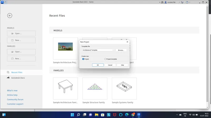
RESULT :
From the file menu, we have created a new project (Structural / Architectural / Construction template ) and we have named the project appropriately.
2.
AIM : Save the new project file. Close and open using icons from file toolbar
INTRODUCTION :
Revit is an autodesk project and building information modelling software for architects, structural engineer, mechanical and electrical engineers. in this project we will learn how to save new file and how to open and close the file.
PROCEDURE :
- go to file > select save > choose destination folder > name the project as 'revit project-1' > press save
- go to file > select close > file will close
- select open > select the file you want to open or just view icon of previous file appear select it
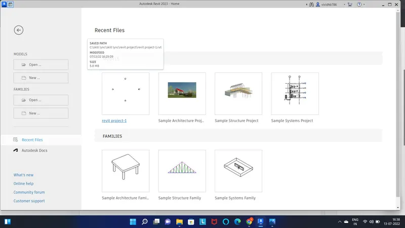
RESULT :
we have Saved the new project file. we have learned how to Close and open using icons from file toolbar.
3.
AIM :
From the architecture/ structure toolbar familiarize with options to draw a wall. Create a rectangular layout of walls of about 40’-0” X 35’-0”
INTRODUCTION :
Revit is an autodesk project and building information modelling software for architects, structural engineer, mechanical and electrical engineers. we will draw rectangular layout of wall.
PROCEDURE :
- open the revit software
- in recent file > previous file icon will appear > select it
- click on wall which is in architecture tab
- go to draw tab > select line command
- draw a horizontal line of 40'> then vertical line of 35'
- make rectangle of 40' x 35'
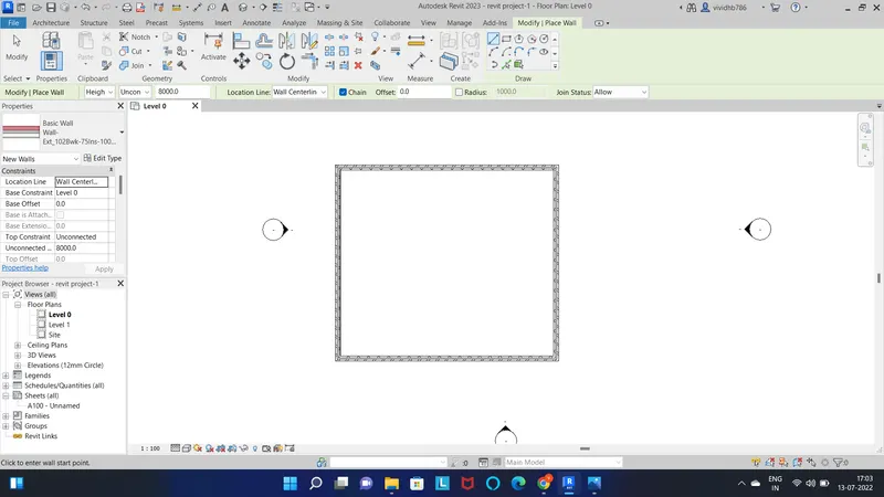
RESULT :
we have Created a rectangular layout of walls of about 40’-0” X 35’-0”
4.
AIM : From the Annotate toolbar use the aligned option to add dimensions to the layout.
INTRODUCTION :
Revit is an autodesk project and building information modelling software for architects, structural engineer, mechanical and electrical engineers. we will learn how to provide dimension using aligned option.
PROCEDURE :
- we have already created a rectangle as in above project
- give dimension to it
- go to annotate tab > select aligned dimensions > select length of object
- provide dimensions
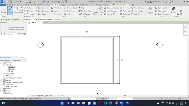
RESULT :
From the Annotate toolbar we have used the aligned option to add dimensions to the layout.
5.
AIM : Use the properties browser to switch to different wall types
INTRODUCTION :
Revit is an autodesk project and building information modelling software for architects, structural engineer, mechanical and electrical engineers. in this we will learn how to use properties browser to switch different wall types.
PROCEDURE :
- select the wall
- go to properties browser > go to wall type > select any of it
- wall type will change
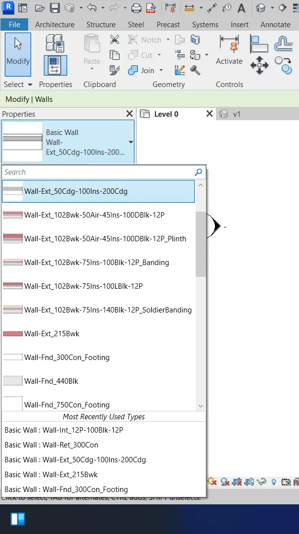
RESULT :
we have Used the properties browser to switch to different wall types
6.
AIM : Create a 3D view from the view toolbar and save the view with the appropriate name
INTRODUCTION :
Revit is an autodesk project and building information modelling software for architects, structural engineer, mechanical and electrical engineers. in this we have created 3d view from the tool bar and save the view with appropriate name.
PROCEDURE :
- open revit
- we have already open rectangular layout
- on top of the bar > select 3d view
- on right side there is view cube > right click of mouse > select save view > name the view as 'v1' > press ok
- view will be saved
RESULT :
we have Created a 3D view from the view toolbar and saved the view with the appropriate name bas V1.
7.
AIM : Navigate through the 3D model using the view cube. Orbit/pan through the model layout created
INTRODUCTION :
Revit is an autodesk project and building information modelling software for architects, structural engineer, mechanical and electrical engineers. in this we will learn how to navigate through 3d model using view cube.
PROCEDURE :
- go to view > select user inerface > select the navigation bar
- at right side bottom of view cube there is symbol of navigation bar
- select it
- use the orbit and pan option for layout
RESULT :
we have Navigated through the 3D model using the view cube. Orbit/pan through the model layout created
8.
AIM : Use the visibility settings option below to switch model to shaded, realistic, hidden lines options
INTRODUCTION :
Revit is an autodesk project and building information modelling software for architects, structural engineer, mechanical and electrical engineers. in this we will learn how to use the visibility setting
PROCEDURE :
- at the bottom bar > select visual style
- select hidden style
- select realistic view
- select hidden view
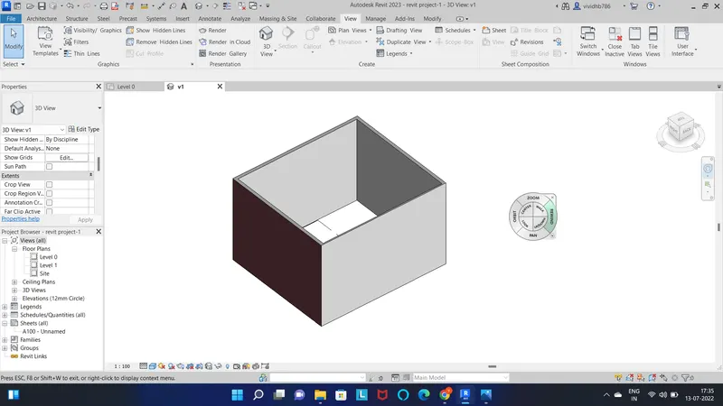
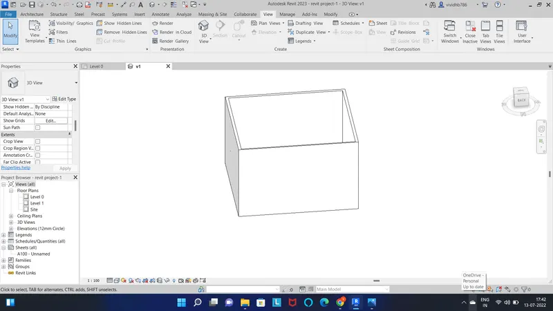
RESULT :
we have Used the visibility settings option below to switch model to shaded, realistic, hidden lines options.
9.
AIM : Turn the sun path on and off to view shadings in the layout created
INTRODUCTION :
Revit is an autodesk project and building information modelling software for architects, structural engineer, mechanical and electrical engineers. in this we will learn how to turn the sun path on and off.
PROCEDURE :
- at bottom of screen beside visual style there is sun path
- select it > select sun path on or off
- we can use sun setting for different location.
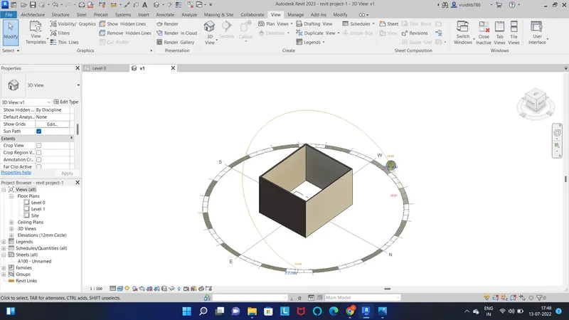
RESULT :
we have learned how to Turn the sun path on and off to view shadings in the layout created.
10.
AIM :
Use the Manage toolbar to enter project settings, project name, and project issue date (choose according to your convenience).
INTRODUCTION :
Revit is an autodesk project and building information modelling software for architects, structural engineer, mechanical and electrical engineers. in this we will learn how to manage toolbar to enter project setting, name and issue date.
PROCEDURE :
- we have already open project
- go to manage > select project information icon > edit the information name, date etc.
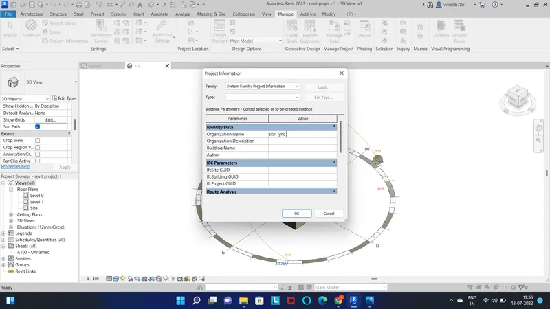
RESULT :
we have Used the Manage toolbar to enter project settings, project name, and project issue date (choose according to your convenience).
11. What is the Analyze toolbar used in Revit? How it is beneficial for design and modelling?
ans-
- analyze toolbar helps you to perform analysis on our structural buildings.
- boundary conditions of analyze tool bar defines point, line and area boundary conditions in analyticl model.
- loads of analyze tool bar applies point, line and area loads to the model.
- it is beneficial because it verify the boundary conditions.
- it is beneficial because it adds and edit loads for analytical model
12. What are the links that Revit supports to be linked to the model?
ans-
a. link revit - this allow to link another revit model to the current model . e.g we can link model together to specify the relative individual building on a campus or to coordinate efforts across disciplines
b. link IFC - it links ifc file to current project to reference its information for additional design of work
c. link CAD - it links autocad file to curent revit projects
d. link topography - if the civil engineer has done topography detailing in other software such as civil 3d it can link to revit project.
13. Why do you need the Collaborate tab in Revit? How it supports modeling and its efficiency
ans.
- collaborate tab in revit enables the worksharing through worksharing usee on same local area network can work together in same revit model.
- it keeps the all parties updated with the curent project via worksharing
- it allows the key design feature to communicate effectivelyvia visual template
- it allow user to divide model into workspace